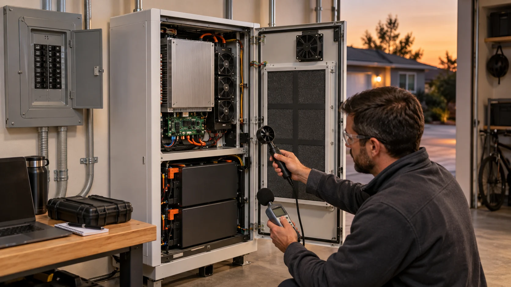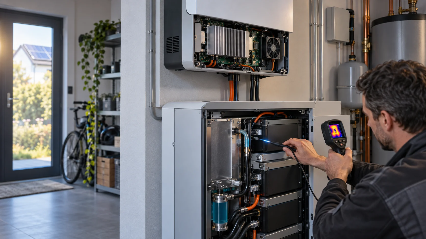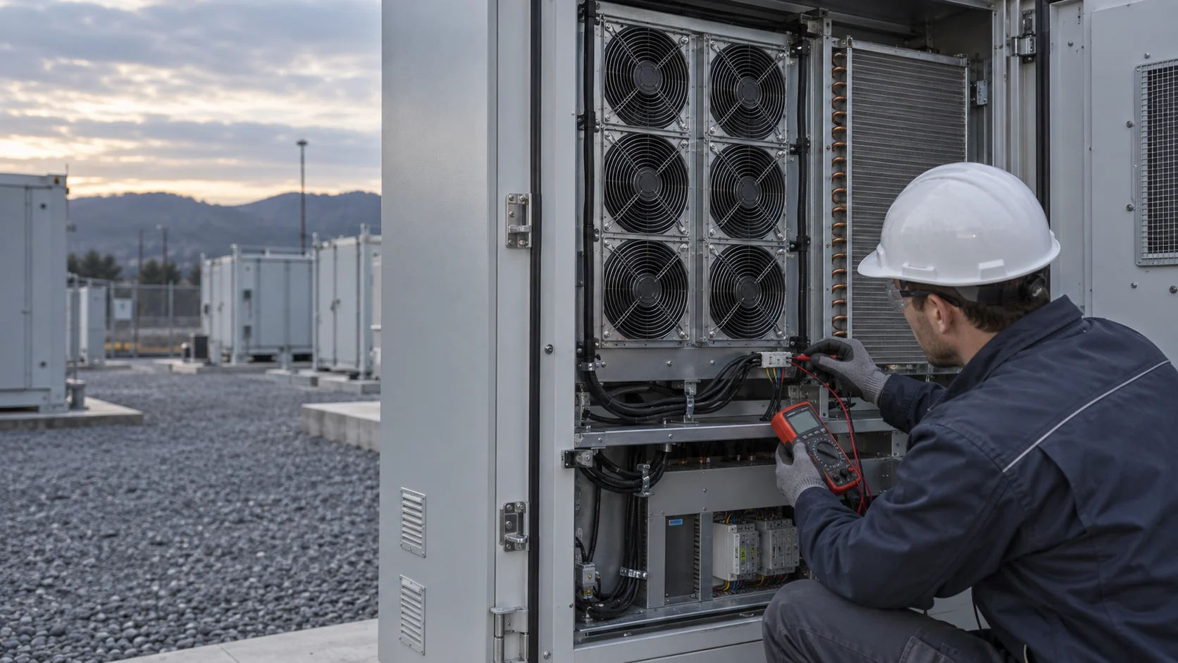
A Fixed Dirty-Filter Pa Value Can Mislead a Variable-Speed BESS
Filter pressure drop changes with air flow. A threshold copied from another cabinet, or read at another fan speed, produces both nuisance alarms and missed restrictions.
A differential-pressure transmitter measures the difference between two defined points. It is useful for trend and service decisions only when the pressure taps, filter type, panel condition and fan state are documented. It is not an airflow meter, and it cannot prove that all the air it 'saw' reaches the coil or the protected equipment.
The variable-speed problem is not subtle. Pressure drop across a filter follows the air velocity through it, and roughly with the square of that velocity, so the same physically loaded filter produces three different readings at three fan commands. A cabinet that runs a night setback at 40 percent command shows about one sixth of its design-airflow pressure drop, on the same dirt. A fixed 250 pascal alarm programmed from a full-speed test will stay silent through months of loading that only appears when the fan is asked for design flow.
ASHRAE Guideline 36 provides the controls principle: the high-limit pressure drop at the current airflow relates to the filter manufacturer limit at design airflow, with the transducer accuracy setting the practical lower measurement boundary. The equation and any alarm delay are a control-design reference, not a universal setting for every BESS. Use the filter supplier specification and the project's approved air path.
This article addresses routine normal-cooling maintenance. It does not define emergency ventilation, fire response or battery-safety requirements.

Pressure Drop Follows Velocity, and the Exponent Grows With Loading
Two exponents matter here: the clean-filter square law and the loaded-filter exponent in the alarm logic. Both come from the same physics.
For a clean filter at a fixed media condition, pressure drop scales close to the square of the air velocity: half the airflow, one quarter the pressure drop. That square law is why the night-setback cabinet in the figure above can hide a badly loaded filter from a fixed threshold.
ASHRAE Guideline 36 uses a slightly different exponent for the alarm line, expressing the high limit at current flow as DP = DP100 times x to the power 1.4, where DP100 is the filter manufacturer's final pressure drop at design airflow and x is the airflow fraction. The 1.4 exponent reflects how a loading filter's own resistance grows faster than a clean one as flow rises. It is a controls reference, not a substitute for the supplier's tested data.
Worked transparent example: a filter with an approved final pressure drop of 200 pascals at design airflow gives a high limit of about 76 pascals at 50 percent airflow, before the project subtracts transducer accuracy and alarm delay. Read the same logic in reverse and the trap is visible: a cabinet whose controller holds 60 percent airflow in cool weather will sit near 100 pascals no matter how dirty the filter is, until a heat wave forces design flow and the alarm seems to appear overnight.
The honest alternative many sites choose: normalize the reading in the controller itself. Divide the measured differential pressure by the clean baseline recorded at the same command, and alarm on the ratio, typically two to three times clean. This costs one commissioning measurement per cabinet configuration and removes the speed from the equation entirely.
Build the Alarm From a Clean Baseline and the Approved Filter Limit
The maintenance threshold belongs to the installed filter and duty, not to a generic number.
First record the approved filter model, orientation, gasket condition, clean baseline differential pressure, pressure-tap locations, fan command or speed, local intake condition and cabinet panel and louver state. Retain the filter manufacturer's final-pressure-drop limit at its stated design airflow. That establishes what the project approved before dust loading changed the system curve.
Then define the comparable operating state. If the BESS uses PWM or another variable-speed control, compare pressure records at a matched load and speed, or use an approved normalized method as described above. For a transparent example only: if the filter supplier limit at design airflow is 200 pascals, the Guideline 36 relationship gives about 76 pascals at 50 percent of design airflow, before considering measurement accuracy and alarm persistence. Do not program that example into a controller without the approved filter data and a validation test.
| Input | Why it matters | Record with it |
|---|---|---|
| Filter supplier final-pressure-drop limit | Sets the approved design reference | Filter part, rated airflow, test condition |
| Clean installed baseline | Shows real panel, gasket and louver losses | Tap locations, fan state, local intake |
| Fan command / speed | Pressure changes with operating flow | PWM, FG/tach, voltage, control mode |
| Sensor capability | Prevents noise or drift becoming a service alarm | Range, accuracy, zero check, alarm delay |
| Thermal response | Confirms the service state still protects equipment | Named temperature points at matched load |
Interactive: Compare a Filter Trend at Three Operating States
Switch the state to see why a pressure value needs its fan condition and thermal evidence beside it.
The interactive is qualitative. It does not calculate a filter change point, a system curve or a battery temperature. Use the actual filter specification, the installed pressure taps and the project test plan for numbers.
Install the Transducer So the Reading Deserves Trust
Field experience with low-pressure measurement is blunt: a decent sensor with poor taps reads fiction, and placement errors alone are commonly quoted in the five-to-twenty percent range.
Tap placement comes first. Put the taps on the side of the duct, not the bottom, so condensate and debris drain away instead of settling into the lines. Keep them in straight duct away from elbows, dampers, transitions and the fan itself; a common rule asks for roughly five duct diameters of settling length upstream of the taps. Where the velocity profile is uneven, use multiple taps or a averaging ring across the duct face, because a single tap samples one streamline of a mixed flow.
The impulse lines should be short, equal in length, and sloped so that anything condensing in them drains back toward the duct rather than into the sensor; for air service a downward slope from the transmitter toward the taps on the order of 1:12 is standard practice. Quarter-inch tubing is usual for clean air. Unequal lines on the two ports add a standing error that no later calibration removes, because the error moves with the weather.
Choose the sensor span to match the job: a filter that loads from 80 to 300 pascals wants a 0-to-500 pascal class device, not a transmitter whose accuracy is quoted as a percent of a range ten times wider. Capacitive cells hold zero better over years; piezoresistive cells tolerate overpressure better. Either way, commission the zero with both ports equalized, in the final mounted position, and check the span against a reference before the reading becomes an alarm threshold.
Alarm Logic: Persistence, Hysteresis and the Three Trend Shapes
The alarm decision matters as much as the threshold. Three trend shapes separate normal loading from sudden failure.
A slow, steady rise over weeks is normal loading: schedule the filter change. A sudden jump in hours is a different event: collapsed media, a blocked intake after a storm, or a louver slamming shut. A sudden drop is the quiet danger: a torn filter, a blown-out gasket or a leaking impulse line, all of which restore a low reading while unfiltered or short-circuited air keeps flowing. An alarm tuned only for high values misses every one of those.
Give the alarm a persistence window of minutes, not seconds, so that a fan start transient or a command step does not page the duty technician, and give it hysteresis so a reading hovering at the threshold does not chatter. Log the raw value continuously even when the alarm is quiet; the trend after a filter change tells you the true clean baseline of the next cycle.
Match the response to the pattern. Slow rise: order the filter, plan the truck roll. Step change up: inspect the intake and media physically before raising fan speed, because forcing maximum PWM through a collapsed filter only finishes the job of destroying it. Step change down with an unchanged command: suspect the filter fit or the measurement chain first, and check what the module temperature did at the same moment.
Validate the Alarm Before You Rely on It
A good alarm creates an actionable service decision instead of a new dashboard number.
Commission the clean baseline with the service door, guard, louver and filter frame in their intended positions. Confirm the transmitter zero and the named upstream and downstream taps. Run a representative thermal load or a permitted power step, and time-align differential pressure, PWM command, FG feedback, voltage and current, and the named temperature points.
When the trend rises, inspect the entire path before replacing a fan: uneven or damp filter loading, collapsed media, damaged gaskets, a blocked intake grille, coil fouling, open panels and intake-to-exhaust recirculation all change the evidence. A dark filter can remain acceptable when its approved pressure and thermal response are normal; a clean-looking filter can still restrict flow. The decision needs the measured chain, not appearance alone.
If the installed duty repeatedly consumes all available fan-speed headroom before the approved service threshold, correct the restriction or revise the required fan pressure capability. Do not hide an undersized path by permanently forcing maximum PWM.
- Keep a clean baseline for every approved filter and cabinet configuration.
- Use a defined alarm persistence period to avoid transient nuisance alerts.
- Inspect filter fit and bypass paths, not only media color.
- Compare pressure at matched fan speed, or use approved normalized logic.
- Confirm temperatures and available control headroom after every service action.
Filter Loading Moves the Other Four Signals Too
Differential pressure is the earliest signal in the chain, but it is not the only one that moves, and the pattern confirms the diagnosis.
At a fixed PWM command, a loading filter drags the operating point left on the fan curve: speed droops a little, current rises a little, and the module temperature rise follows with the delay of thermal mass. At a fixed speed target, the same loading shows up almost entirely as rising current. Either way, by the time the module temperature moves, the restriction has been growing for weeks; the pressure tap saw it first and the fan bill paid for it in the meantime.
That ordering is useful for triage. Pressure up with fan signals normal: air-path restriction, service the filter. Pressure up with current up and speed down: heavy loading already loading the bearing; change the filter before the impeller deposits and the bearing wear start reinforcing each other. Pressure normal but temperature up: the restriction is not in the filter, and the likely suspects move to recirculation, bypass or a failed louver.
The energy argument belongs here too. A fan pushing through a loaded filter spends its life further out on its curve at the same delivered airflow; across a fleet, timely filter service on pressure evidence is one of the cheapest energy savings available in the enclosure, which is why the DOE maintenance guidance treats pressure drop, not calendar time, as the replacement trigger.
Fleet Practice: One Baseline per Configuration, Not per Site
Sites drift. Filters get substituted, panels get left off during service, and the clean baseline quietly stops describing the hardware.
Record the clean baseline per cabinet configuration, meaning filter model, panel state, louver type and tap locations, and re-record it after every filter change and any enclosure modification. A baseline captured with a service door open, or with a substituted filter of a different class, will sit in the historian looking authoritative while describing hardware that no longer exists.
Loading rate is site-specific and seasonal. A site next to a harvest field, a desert road or construction work can consume a filter in weeks that a coastal site runs for a year; the first month of trend data should therefore set the inspection interval, not the datasheet, and the interval should be reviewed after any change in the surroundings. Dust events leave a signature: a fast step in the trend at a known date is a story, not noise.
Finally, keep the records where the next technician will find them: filter part and substitution approvals, tap locations, transmitter range and last zero check, alarm thresholds and their normalization method, and the module temperature response at the last accepted service state. An alarm nobody can trace back to a baseline is a number, not a maintenance system.
Where MEGA Tech Fits In
Filter service data is also the missing input for a credible fan requirement, and that is where we come in.
What we can do: use the clean and service-state records to size and build a custom DC or EC fan sample, or evaluate a cost-competitive replacement, for the real installed pressure, not the catalogue one. We take the filter and coil pressure data, the required airflow at a stated pressure, the available fan space, voltage, the PWM/FG/RD interface, local inlet conditions, the noise limit and the approved pressure and thermal acceptance plan, and we deliver a sample that demonstrates the agreed installed working point behind the same filter, coil, louver and sealing arrangement expected in production. If the filter data shows the fan has been living at maximum speed to survive, we will say the path needs a different fan rather than quoting a bigger one into the same restriction.
What we need from the customer: the measured clean and loaded differential pressures at a stated command, the filter part number and its approved final pressure drop, the airflow target at a stated pressure, voltage and tolerance, the control and feedback interface definition, connector and harness constraints, the space envelope, the noise target and where it is measured, and the acceptance plan the site will actually run.
Where our scope ends: we do not supply filters, differential-pressure transmitters or the controller that hosts the alarm logic, and we do not write the normalization routine. A mechanical copy of a fan is not a deliverable we will defend; the sample is judged in the enclosure, at the working point, with the customer's own evidence chain.
Recommended Fan Starting Points
These catalogue series may be suitable starting points for this application. Final selection depends on the installed airflow, static pressure, voltage, noise target and operating environment.
Request a sample for validation on your equipment.
Engineer FAQ: BESS Filter Differential-Pressure Alarms
The FAQ keeps pressure monitoring tied to a specific filter, fan state and acceptance test.
Q: What Pa value should trigger every BESS filter alarm? A: There is no universal value. Start from the filter manufacturer limit at its stated design airflow, the installed baseline, sensor capability and the project thermal acceptance criteria.
Q: Can a pressure transmitter prove airflow? A: No. It measures the difference between its two taps. Use it with fan state, inspection and thermal or calibrated airflow evidence.
Q: Why does filter differential pressure fall when the fan slows? A: Lower flow means lower resistance, roughly with the square of velocity on a clean filter. Compare matched fan states or use normalized logic rather than one universal value.
Q: Where should the pressure taps go? A: On the side of the duct, in straight runs away from elbows, dampers and the fan, with short equal impulse lines sloped so condensate drains back to the duct.
Q: The reading suddenly dropped with no service visit. Is the filter clean again? A: Almost certainly not. A torn filter, a blown gasket or a leaking impulse line restores a low reading; check the module temperature and inspect the filter fit before believing it.
Q: Should maximum PWM be the first response to a dirty-filter alarm? A: No. Check control headroom, fan limits, the installed restriction and the thermal response. Service the air path rather than masking a growing restriction.
Q: What transmitter range and accuracy are typical for this job? A: A 0-to-500 pascal class device covers most enclosures, with the span matched to the real loading range and the zero commissioned in place with both ports equalized.
Q: What does MEGA Tech need to review a BESS fan replacement? A: The current fan or drawing, the filter, coil and louver path, measured clean and service states, target airflow at pressure, voltage, PWM/FG/RD interface, noise target and acceptance plan.
Questions for a Design Review
Bring this list to the review; every unanswered question becomes a field argument later.
- Which filter final pressure drop did the project approve, at what design airflow, and where is it filed?
- Is the clean differential pressure recorded per cabinet configuration, with tap locations and fan state?
- How does the alarm logic account for fan speed: matched-state comparison, normalization, or the Guideline 36 exponent?
- What persistence and hysteresis protect the alarm from transients, and who approved them?
- Does anything in the logic watch for a sudden pressure drop, or only a rise?
- What are the tap locations, the transmitter span, and the date of its last zero check?
- What module temperature response, at matched load, confirms a filter service restored the intended state?
- After a dust event or a filter substitution, who re-records the baseline and re-rates the alarm threshold?