Fan RPM Is Evidence of Rotation, Not Proof of Cooling Airflow
A BESS controller can show a healthy PWM command, tach feedback and no fan alarm while the air path no longer delivers the flow needed at the protected equipment.
FG or tach feedback is valuable: it confirms that a fan is rotating at a reported speed. It does not measure airflow through the filter, coil, louver, duct, battery compartment or any other installed restriction. The airflow a fan actually delivers is set where its pressure-flow curve meets the assembled system resistance, not by the speed line alone. Two cabinets can report identical speed feedback while delivering very different cooling flow, because the air path between the fan and the cells decides how much of that speed becomes flow.
A loaded filter, a fouled coil, a blocked intake, a changed panel, a loose gasket, a recirculation path or a poor inlet transition can all move the installed operating point without immediately creating a speed fault. AMCA describes these installation losses as system effect: non-uniform inlet or outlet flow and nearby obstructions reduce the performance obtained in a real system compared with a laboratory rating. The controller sees rotation where rotation exists; it has no sensor for the flow that no longer arrives.
This guide addresses normal BESS thermal management only. It does not define thermal-runaway response, emergency ventilation, fire protection or battery-safety acceptance. Those functions require their own project-specific hazard analysis and approvals.

Capture the Same Operating State Twice
Do not compare a hot, loaded-filter alarm event with a clean-filter baseline taken at another load and intake condition.
Before changing parts, capture a reference record at a defined operating state: battery power or thermal load, local intake temperature, cabinet panels and louvers fitted, filter condition, control mode and observation time. Then collect the same record during the suspected condition. A matched comparison makes the evidence useful; a single speed screenshot rarely does.
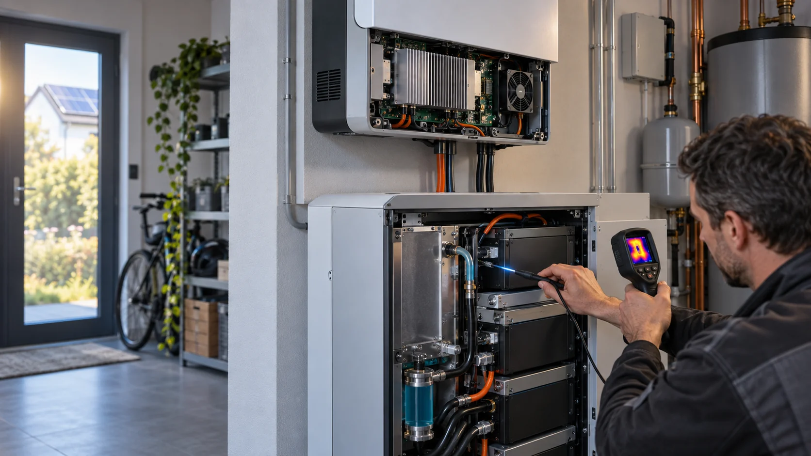
At minimum, time-align fan command, FG/tach feedback, supply voltage, fan-branch current where available, differential pressure across the relevant restriction, intake and discharge temperatures, and the project-defined protected-equipment temperatures. If airflow can be measured at an agreed plane, retain the method and the plane between the two records. Pressure is not a direct airflow value, but a changing pressure record can show where the installed path changed when it is read alongside the other signals.
For an illustrative screening example, suppose a cabinet runs the same requested state on two days. The command and the reported speed are similar, yet the filter-to-coil differential pressure rises and the downstream temperature response becomes slower. That pattern is a reason to inspect restriction, bypass and sensor placement. It is not enough evidence to declare a bad fan, and it is not a basis for assigning a universal airflow-loss percentage.
| Signal or inspection | What it can establish | What it cannot establish alone |
|---|---|---|
| PWM command and FG/tach | Requested speed and reported rotation | Installed airflow, coil flow or thermal acceptance |
| Supply voltage and current | Electrical condition and possible loading change | Fan curve position or restriction location |
| Differential pressure | Change across a named filter, coil or path section | A universal airflow value without a calibrated method and geometry |
| Temperatures with timestamps | Thermal response at named sensor locations | The exact mechanical cause without air-path inspection |
| Physical air-path inspection | Blocked grilles, bypass gaps, gasket, panel and louver condition | Whether the fan meets its required pressure-flow point without measurements |
Interactive: Trace the Signal That RPM Cannot See
Switch the installed states to see which evidence should change together before assigning the fault to a fan module.
This qualitative tool is not a CFD model, an airflow meter or a BESS safety model. It helps structure a field record around the difference between rotation feedback and installed cooling flow.
Step through filter states, intake blockage and recirculation to see why one signal alone cannot locate the fault: each installed state changes a different subset of the record.
Find the Point Where the Fan Curve Meets the System Curve
The speed line says where the fan spins. The intersection of two curves says how much air moves.
Every fan has a pressure-flow curve: high flow at low pressure, low flow at high pressure, one point for every speed. Every installed path has a system curve: the pressure the path demands rises roughly with the square of the flow, as fan application guides such as the Greenheck motor-sizing reference describe. The cabinet operates where the two curves cross. Change either curve and the crossing point moves.
This is why a loaded filter can reduce airflow with no change on the speed line. As the media loads, the system curve steepens: the path demands more pressure at every flow. The operating point slides along the fan curve toward lower flow and higher pressure. The fan still spins at the commanded speed, the tach still agrees, and the alarm list stays clear, while the flow delivered past the coil falls. Nothing in the electrical record contradicts the controller's belief that all is well.
The same logic covers the other path changes: a crushed intake screen, a door gasket leaking at its corner, a coil fouled on the upstream face, a blanking plate left out after service. Each one steepens or short-circuits the system curve in its own way, and each one hides behind a healthy speed reading. The record in the table above exists to catch exactly these moves.
Know What Raising the Speed Would Cost
Raising the command is the reflex answer. The fan laws set its price before the test starts.
The fan laws relate speed, flow, pressure and power when the fan and the air density stay fixed: flow follows speed, pressure follows the square of speed, and power follows the cube. Greenheck's application guidance gives the worked shape of this rule: a 10 percent rise in speed buys about 10 percent more flow, requires about 21 percent more pressure capability, and costs about 33 percent more input power. In their selection example, moving 25 percent more air through the same system takes 25 percent more speed, 56 percent more static pressure and nearly double the shaft power.
Applied to a diagnostic, the laws cut both ways. If a modest speed increase restores the thermal response, the system was probably riding a steeper curve than designed, and the path deserves an inspection anyway. If the same increase changes nothing, the flow is escaping somewhere the speed cannot reach - a bypass gap, a recirculation loop, a disconnected duct section - and more speed only spends more watts on the wrong problem.
There are also limits independent of the diagnosis. Every fan has a maximum speed, a voltage window and a power rating. The fan control logic guide explains how command, feedback and alarm behavior interact, and the high ambient margin guide shows why a cabinet that already rides near its limit has no speed headroom to spend on diagnosis.
Read the Pressure Drop Across a Named Restriction
Differential pressure is the closest thing the cabinet has to an airflow gauge. It only means something when the taps have names.
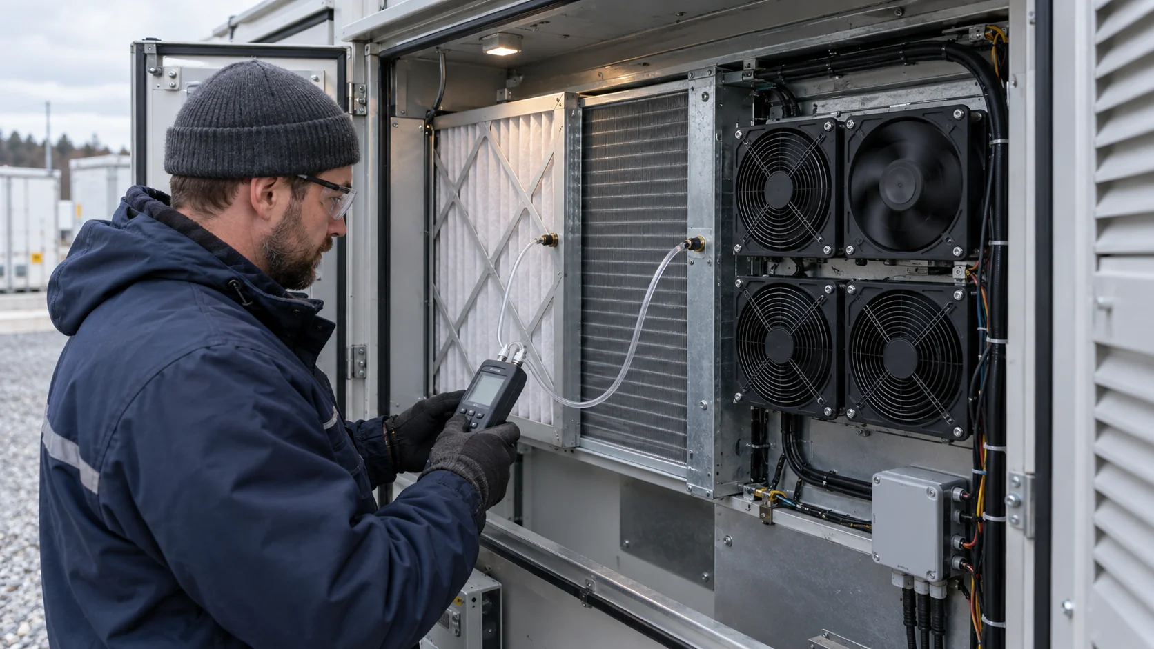
Install or use pressure taps across one named restriction - the filter bank or the coil - and keep their locations unchanged between the baseline record and the fault record. A rising pressure drop at constant command means the path is loading or blocking; a falling one can mean a bypass has opened and air is finding a way around the restriction instead of through it. Neither reading replaces an airflow measurement, but together with the thermal response they usually identify which half of the path changed.
Match the pressure record to the filter state. The filter differential pressure guide pairs thresholds, logging intervals and change-out triggers into a maintenance plan, and the same record doubles as diagnostic evidence: the filter differential pressure guide sets the pattern. When the pressure record and the speed record travel on the same time base, the loaded-filter case shows its signature - speed flat, pressure climbing, downstream response slowing.
Remember that the taps read only what sits between them. Coil fouling, louver blockage or a shifted panel upstream of the taps can move the whole curve while the named reading stays quiet. That is why the pressure record is one instrument in the set, not the verdict.
Inspect the Restriction and Bypass Path Before Replacing the Fan
The fastest correct fix is usually in the surrounding assembly, not in the fan label.
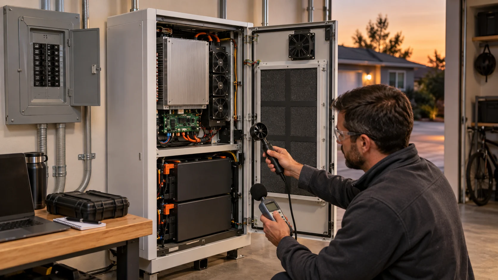
Walk the complete serviceable path: intake clearance, weather louver, guard, filter face and gasket, coil face, plenum, fan shroud, door seals and exhaust. Look for uneven dust loading, damp or collapsed media, a filter installed in the wrong direction, blocked louvers, objects stored inside the intake clearance, open service panels, missing blanking plates and dust tracks downstream of a supposed filter seal.
A restrictive guard, an abrupt transition, a side entry, a short return bend or leakage around the module can add loss or cause recirculation. Where the flow is escaping rather than blocked, the fault is a bypass: air that skips the filter or the rack entirely. The bypass and dead-zone guide maps the usual gap locations and how they distort both the flow and the pressure reading.
If the restriction is clean and the path is intact, compare the required installed pressure-flow point with the correct fan curve at the actual voltage and control condition. Confirm fan orientation, wiring, commanded speed range and any fan-specific FG/RD behavior from the applicable datasheet. Do not infer protection rating, bearing construction, temperature limit or alarm behavior from a similar-looking model.
- Photograph the filter, louver, panel and cable-routing condition with the test record.
- Name the pressure taps and keep their locations unchanged between baseline and fault checks.
- Record whether access doors, guards and blanking plates are fitted during every measurement.
- Check intake-to-exhaust separation for warm-air recirculation, not only visible blockage.
- Treat an alarm-clear condition as a control result, not as thermal acceptance evidence.
Recirculation Warms the Intake Without Moving the RPM Line
A fan can deliver its full airflow and still fail the cells, if the air it delivers is already hot.
Cooling depends on mass flow and on the temperature difference between the intake air and the cells. Recirculation attacks the second half: exhaust air that loops back to the intake raises the inlet temperature while every electrical signal stays normal. A cabinet whose intake moves from 32 C to 41 C because warm exhaust re-enters the inlet has lost 9 C of its air-side margin at the same airflow, on the same speed line, with the same alarm status.
The record catches this with one extra channel: intake temperature at a named point, time-aligned with the rest. Compare it with ambient. A gap between site ambient and cabinet intake temperature that grows with load or with wind direction is a recirculation signature - and the high ambient margin guide explains how much margin to hold for the site's own heat before the path is asked to absorb any more.
Physical inspection completes the picture: intake and exhaust louver separation, wind skirts, service-door orientation, and anything stacked between the exhaust plume and the intake face. Outdoor cabinets inherit the weather; a path that recirculates on a calm day may seal itself in with its own exhaust on a still, hot evening.
Complete the Electrical Record With Voltage and Current
Speed feedback and current, read together, separate an electrical cause from an air-path cause.
A 24 V DC fan usually carries a rated window of roughly 21.6 to 26.4 V. As the supply at the fan connector falls toward the low end, the maximum speed the fan can reach falls with it - a command near 100 percent may no longer be reachable, and the controller sees a speed deficit that looks like a fan fault but is a wiring or supply fault. Measure voltage at the connector, not only at the distribution bus, because harness loss grows with current and with every terminal in the path.
Current completes the pair. At the same command and voltage, a fan working against a higher pressure than its baseline draws more current; a fan with a failing stage or an intermittent winding can draw less. Either departure from the matched baseline is evidence, but only the baseline makes it readable - which is why the matched-state record comes first in this guide.
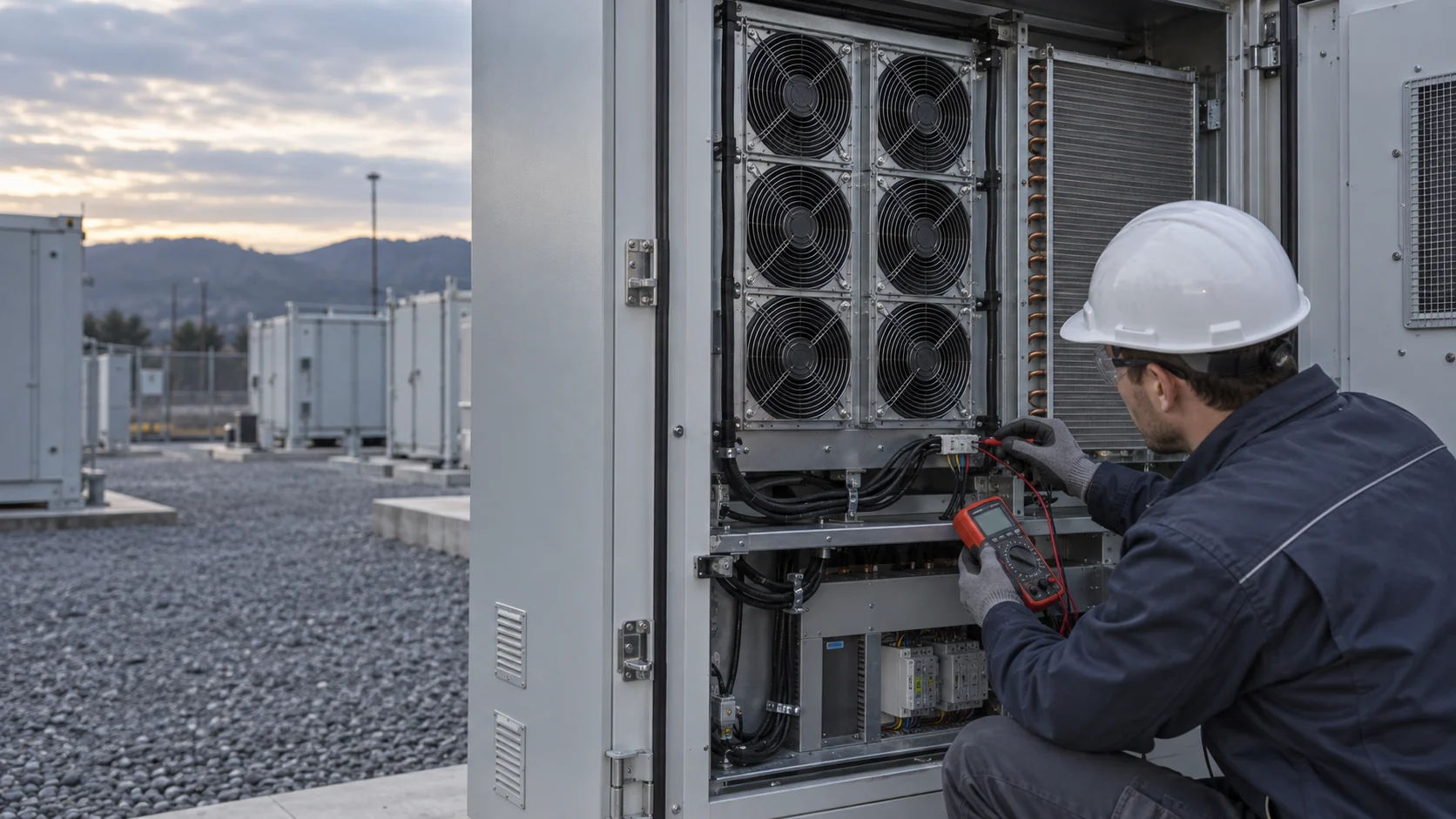
Where branch current is not instrumented, a clamp meter reading at the fan connector during the two records still closes the loop. Record it with the command and the voltage, and the electrical half of the diagnostic stands on numbers instead of impressions.
Turn the Record Into a Fan Requirement
A replacement or custom sample should be specified from the verified installed point, not from frame size or free-air flow alone.
When the evidence does land on the fan, turn it into a requirement: available frame and depth, mounting and sealing arrangement, target airflow at the stated static pressure, voltage range, PWM command range, FG/tach and RD/alarm interface, local inlet condition, noise target, operating cycle, and the exact acceptance test for both the normal and the service state. If the original fan is available, include its label, drawing and measured installation data, but do not assume mechanical fit proves a comparable cooling result.
MEGA Tech builds custom DC and EC cooling fans - axial and backward curved centrifugal - for enclosures like this one, and this diagnostic record is the document we work from. Bring us the two matched records and we translate them into a fan requirement at the operating point: airflow at the static pressure the installed path imposes in the loaded state, the voltage window the harness actually delivers at the connector, and the control interface the cabinet uses. We select by operating condition rather than by frame size, and samples are validated on the customer's real machine, in the same filter, coil, louver and enclosure path the record describes.
To quote and build the sample we need from you: the airflow and static pressure at that airflow from the record, the temperature and altitude reference for the site, supply voltage and its tolerance at the fan connector, the control and feedback interface including connector type, the space available, the noise target at the boundary, and the life assumption in years or hours. We do not supply coils, liquid cooling loops, controllers, enclosure safety design or emergency ventilation - those stay with the system integrator, and our fans must prove themselves inside your architecture, not around it.
Where the diagnosis ends in an array decision instead - one fan unavailable, or a fleet-wide check - the array N+1 guide and the predictive maintenance signals guide carry the same record discipline into availability planning and early-warning thresholds.
Recommended Fan Starting Points
These catalogue series may be suitable starting points for this application. Final selection depends on the installed airflow, static pressure, voltage, noise target and operating environment.
Request a sample for validation on your equipment.
Engineer FAQ: Normal RPM but Poor BESS Cooling
Short answers that keep electrical feedback, installed airflow and thermal acceptance in their proper roles.
Q: Does normal FG or tach feedback prove that a BESS fan is delivering the required airflow? A: No. It proves reported rotation. Verify the installed air path with the pressure, temperature and, where agreed, airflow measurements at the defined operating state.
Q: Does a higher differential pressure always mean a dirty filter? A: No. It indicates a changing restriction across the named pressure taps, but coil fouling, louver blockage, panel configuration, tap placement and operating condition can also affect the reading. Inspect and compare matched states.
Q: Should we simply increase PWM when battery temperatures rise? A: Only after checking available speed headroom, voltage at the connector, fan limits, installed restriction and thermal response. The fan laws price the increase - roughly 33 percent more power for 10 percent more speed - and it may not correct a bypass or a recirculation path at all.
Q: Can a mechanically identical replacement fan be approved from its maximum free-air rating? A: No. Compare the required pressure-flow point, voltage and control condition, mounting and sealing, interface behavior and a representative thermal test. A free-air maximum is not the installed result.
Q: The tach agrees, the current is normal, and the rack still runs hot. Where is the fault? A: Most often in the path the instruments do not span: a bypass gap, a recirculation loop, an intake preheated by the exhaust, or a restriction outside the pressure taps. Extend the record with intake temperature and a walk-down inspection before touching the fan.
Q: What should we send for a custom BESS cooling-fan review? A: Send the current fan or its drawing, enclosure and air-path photos, target airflow at the stated pressure, voltage and tolerance at the connector, PWM/FG/RD requirements, intake conditions, noise target, expected operating cycle, and the normal plus service-state validation record.
Questions for a Design Review
Bring these to the meeting where the diagnostic plan and the acceptance criteria are approved.
1. Which signals enter the diagnostic record, and are they time-aligned on one clock?
2. Which restriction do the pressure taps span, and who keeps the tap locations constant between records?
3. What intake temperature rise above site ambient is acceptable, and which channel watches it?
4. What speed headroom, voltage window and current envelope does the fan hold at the worst installed state?
5. At what filter pressure drop does the cabinet return to full command or demand service?
6. What acceptance test, on the real assembled path, approves a replacement or custom fan sample?
7. Who owns the baseline records in operation, and where do the two matched states get stored?