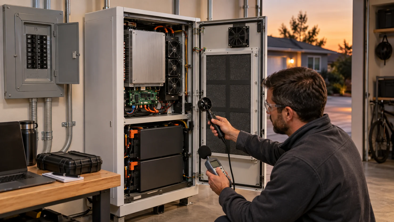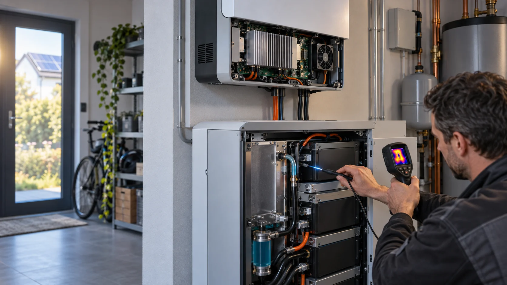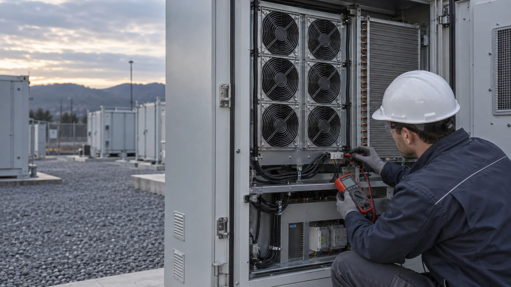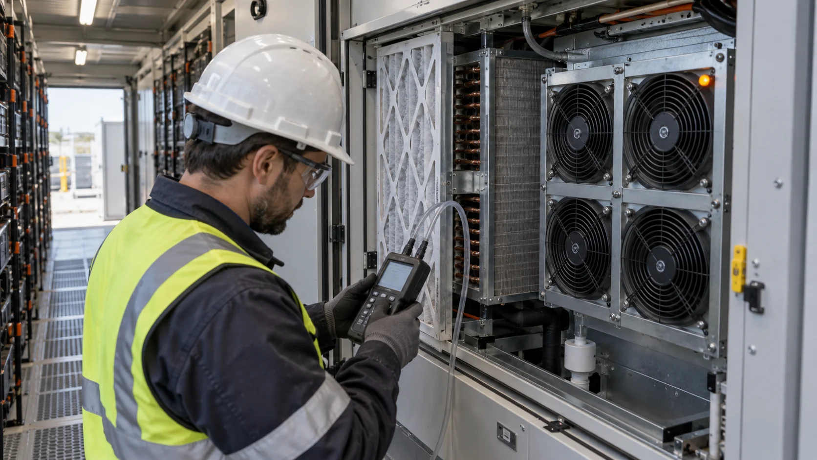
Four Fans Installed Does Not Automatically Mean Three Fans Are Enough
N+1 is a statement about what the array can still do after a fault: it has to prove that the remaining fans meet the agreed normal-cooling requirement with one module unavailable.
A common shortcut is to count fans and assume that one stopped fan removes exactly one quarter of the airflow. The installed result is more complicated. Parallel fans share a system curve, and the pressure, leakage, inactive fan path, inlet geometry, controller response and remaining fan speed all affect where the array settles after a fault.
The count is an inventory. N+1 is a statement about cooling performance. A four-fan array is only a three-fan array in the sense that three fans are still installed; whether those three can hold the agreed airflow at the agreed pressure with the agreed air path is a measurement, not an arithmetic result. That measurement is also what a replacement module has to reproduce, which is why the installed-performance record matters beyond the original build.
AMCA guidance on parallel fans notes that adding a fan without changing the system resistance can deliver less added flow than expected. The same reasoning applies in reverse when one fan stops: the remaining fans do not simply inherit a fixed share of the original flow. A stalled or unpowered module can also become a bypass or reverse-flow path unless the physical arrangement and any backdraft feature have been assessed.
This article addresses normal cooling availability and maintainability. It does not define battery thermal-runaway protection, emergency ventilation or safety approvals. U.S. Department of Energy safety guidance treats normal cooling and propagation prevention as distinct system functions, and they are specified and tested differently.
Interactive: Compare the Array States Before You Call It N+1
Switch states to see why the fault path and the service restriction need to be part of the same test plan.
The three states in the model are the three states that have to appear in the validation record: the clean baseline, the defined fan-unavailable condition, and the fault combined with the service restriction the equipment will actually be maintained in. A result taken only in the first state says nothing about the other two.
This model is qualitative. It does not calculate a fan-array curve, battery temperature or fault-safe operation. It identifies the signals that should be recorded together in the representative BESS cooling path.
The Inactive Fan Position Is an Air-Path Condition, Not Just an Alarm Signal
A failed module is not only a loss of drive. It is also a change in the flow network, and the direction of that change has to be measured.
Without a backdraft damper or an isolation shutter, the running fans recirculate air backwards through the idle fan position. Published fan-array field guidance puts the penalty at 10 to 20 percent of array airflow, and describes the mechanism precisely: the array loses the failed fan's contribution and then subtracts flow that the remaining fans just produced. That is the difference between an N+1 result that survives a test with one fan unavailable and one that only survives a datasheet.
Array design guidance is consistent on the fix. Each fan in a parallel array should have an isolation damper that closes when that fan fails or is stopped for service, and the same damper prevents the fan being driven backwards at start-up. Damper performance is not a generic purchase: leakage rate, pressure drop, dynamic closure and operating torque are separate properties, tested under a recognised damper standard such as ANSI/AMCA 500-D. Ask for the leakage class at the differential pressure the array actually produces, not for the presence of a damper.
The state of the unavailable module matters as much as the fan count. A stopped module whose blades are free to turn is a low-resistance return path and will be driven backwards by the array pressure. A module left in place but freewheeling behaves the same way in the flow network even though it is not commanded. A module removed for service leaves the frame open unless a blanking plate or shutter closes the aperture. Only the isolated state takes the position out of the flow network altogether, and only that state gives the remaining fans a clean task. Guards, service screens, blanking panels and gaskets add resistance too, so they belong in both the normal and the degraded test configuration; a guard fitted in service but absent from the test is a configuration change that invalidates the comparison.
One more consequence is easy to miss. Where N+1 fan redundancy is specified, published array guidance requires the fans in the N operating condition to be verified inside the recommended operating range of their curves, away from the instability zone, to avoid uneven airflow and pressure, increased noise, and mechanical damage. Ramping the remaining fans up after a fault is exactly the operation that can push them towards that region, so the acceptance test with one fan unavailable is also a stability check.

| State of the module | Change in the airflow path | Evidence to record |
|---|---|---|
| Stopped, damper open | Low-resistance return path; array pressure can drive the rotor backwards | Fault command, blade condition, any reverse rotation observed |
| Freewheeling | Still a path, direction set by the array pressure rather than by the drive | Whether the rotor turned after the fault and in which direction |
| Removed for service | Frame open to the plenum unless a blanking plate or shutter is fitted | Aperture treatment during maintenance and restore procedure |
| Isolated, damper closed | Position removed from the flow network; no recirculation penalty | Damper leakage class at the array differential pressure |
Turn a Fan-Fault Test Into a Production-Ready Requirement
A useful test with one fan unavailable produces a traceable specification for the next sample, not only a pass or fail screenshot.
Run a documented normal baseline first, then introduce the defined fan-unavailable state while retaining the intended panels, filters, louvers and coil. Repeat any required service resistance or high-load state. Time-align thermal response with pressure, control, feedback, electrical input and alarm history so an engineer can distinguish insufficient fan airflow from a blocked path, poor sensor location or controller limitation.
The acceptance criterion has to be stated in the units of the protected equipment. An alarm clearing is not an acceptance result, and neither is the remaining fan reaching its commanded speed. The result is whether the named temperature sensors stay inside the agreed temperature limits for the agreed time window with the defined module unavailable, and whether the array did it without leaving its recommended operating range.
Run the sequence more than once, and not always from the same starting state. A fault that occurs while the array is already at high speed is a different event from a fault that occurs at low load and forces the array to ramp. Both are realistic, and the slower of the two usually decides the permitted intervention window.
MEGA Tech can use this record to develop a custom DC fan module or evaluate a cost-competitive replacement for normal BESS cooling. Provide the existing module or drawing, array pitch and sealing details, target flow at stated pressure, voltage, PWM/FG/RD requirements, expected inlet conditions, noise limit, expected operating hours and the acceptance plan with one fan unavailable. A replacement is not qualified simply because the outer dimensions fit; it has to prove the agreed installed performance in the representative array.
| Step | Configuration | Recorded data | Acceptance |
|---|---|---|---|
| 1 | Baseline, all fans running, documented filter state | Installed differential pressure, command and FG/tach, voltage and current, named sensor map | Reference state recorded, not treated as the result |
| 2 | Defined module unavailable, isolation damper open | Reverse-rotation observation, remaining-fan speed, power, noise | Fault state and permitted degraded window established |
| 3 | Same fault with the isolation damper closed | Same measurement set plus damper leakage class | Remaining fans hold the agreed airflow inside the recommended operating range |
| 4 | Fault plus the service filter state | Differential pressure at the loaded filter, thermal sensors | Thermal acceptance still met, or maintenance trigger tightened |
| 5 | Restore and repeat | Restoration time and procedure, repeat measurements | The result repeats; it was not a one-off |
Where N+1 Cooling Stops and BESS Safety Ventilation Begins
Normal cooling availability and emergency gas removal are two different requirements with two different failure modes. One fan array cannot be counted for both.
Fire codes such as NFPA 855 require energy storage systems to be provided with ventilation or detection capable of keeping combustible gas concentrations below 25 percent of the lower flammable limit. That requirement is sized on enclosure volume and gas generation. Normal cooling is sized on heat load and temperature uniformity. The two numbers do not substitute for each other, and industry safety plans for containerised storage commonly specify the gas-purge system as a separate system from the HVAC that holds battery temperature, with its own redundancy.
The air path matters in both directions. Published CFD analysis of containerised BESS ventilation found that a sealed enclosure accumulated flammable hydrogen concentrations within about a minute, that an exhaust-only configuration without a matching make-up path pulled enclosure pressure to roughly 86 kPa below ambient within about 12 seconds, and that this structural hazard arrived before any gas-removal benefit. The same work recommends a verified intake or pressure-relief path whenever mechanical exhaust runs, pressure-relief cracking pressures in the range of 100 to 300 pascals for typical enclosures, gas sensing at the highest practicable elevation because of buoyancy stratification, and low-pressure interlocks so exhaust fans cannot keep running under vacuum.
That is a different engineering discipline from fan-array N+1, and it is treated that way in practice. Emergency ventilation is normally interlocked so that a failure of the ventilation system shuts the process down rather than being ignored, and its disconnect is marked so that first responders do not switch off the ventilation during an incident.
So when a project states that the cooling is N+1, the first question is which function is being described. An array that holds battery temperature with one fan out is a normal-cooling availability statement with a defined thermal limit and intervention window. It says nothing about gas removal at the code-required concentration limit, which is a separate system with a separate test. Keeping normal cooling and emergency ventilation as two clearly separated acceptance lines is what stops one result being borrowed for the other.
MEGA Tech Scope: What a Custom BESS Fan-Module Sample Has to Prove
MEGA Tech supplies custom DC axial fan modules and can evaluate a cost-competitive replacement for the fans used in normal BESS cooling, with the same performance as established international brands and better service and price.
A replacement module is qualified by the array it is installed in, not by the test bench. The useful starting point is the installed performance: the airflow the module has to deliver at the pressure the real filter, coil and louver produce, at the voltage and control interface the array already uses, with the connector, frame and sealing that let it drop into the same aperture.
The sample can then be tested in the representative array with the same test sequence with one fan unavailable, so the acceptance result is comparable with the original module's record. What MEGA Tech does not offer is facility-level scope: we do not supply the container HVAC platform, the liquid-cooling loop or the emergency gas-purge system, and we do not offer an EC facility fan platform as a MEGA product. The scope is the DC axial fan module and its documented installed performance inside the array the customer already has.
- Existing module or drawing, including impeller, frame, guard and any shutter or damper arrangement.
- Array layout: module pitch, inlet spacing, sealing details and the aperture the module has to close.
- Required airflow at a stated pressure, measured in the service configuration rather than at free air.
- Voltage, PWM speed-control range, and the FG or RD feedback the controller expects.
- Expected inlet air temperature and humidity range, dust and cleaning conditions, and any coastal or corrosive exposure.
- Noise limit at the operating distance that matters for the site, and the permitted maximum speed.
- Expected duty cycle, including the hours at full speed and the number of starts per day.
- The documented normal-state test and the acceptance plan with one fan unavailable, so sample and series parts are judged the same way.
Recommended Fan Starting Points
These catalogue series may be suitable starting points for this application. Final selection depends on the installed airflow, static pressure, voltage, noise target and operating environment.
Request a sample for validation on your equipment.
Engineer FAQ: BESS Fan Arrays and N+1 Cooling
These questions keep the redundancy discussion attached to a repeatable installed test.
Q: Does a four-fan array automatically provide three-fan N+1 cooling? A: No. The array must meet the defined installed airflow-pressure and thermal requirement with one specified module unavailable in the representative air path.
Q: Does one stopped fan always reduce airflow by 25%? A: No. Parallel fan behavior depends on the combined curve, system resistance, leakage, inactive-module path and remaining fan controls. Measure the installed result.
Q: Does normal RPM from the remaining fans prove cooling with one fan unavailable? A: No. RPM confirms rotation. Pair command and feedback with installed pressure, electrical input and relevant thermal measurements.
Q: Is a backdraft damper optional if the array is inside an enclosure? A: No. Without it the running fans recirculate air backwards through the idle position, and published guidance puts that penalty at 10 to 20 percent of array airflow. The damper is what removes the failed position from the flow network.
Q: Should the test with one fan unavailable be run with clean filters? A: Run both. The clean result is the baseline; the loaded result is the state the equipment will actually be maintained in. A clean-path N+1 result cannot be transferred to a loaded filter without evidence.
Q: Can the normal-cooling fan array be counted towards the emergency gas-removal requirement? A: No. Gas removal is sized on enclosure volume and gas generation against a concentration limit, and it is normally specified and tested as a separate system with its own redundancy. It is a different function with its own safety analysis and approvals.
Q: What should be included in a custom BESS fan-array sample request? A: Include the fan or module drawing, array layout and sealing, full air path, required flow at stated pressure, voltage, PWM/FG/RD interface, environment, noise target and the documented normal-state test and the test with one fan unavailable.
Questions for a Design Review
Take these to the review that approves the cooling package, before the array is ordered.
- What exactly is unavailable in the fault case: stopped, freewheeling, removed or isolated?
- What is each fan's design point as a percentage of its maximum airflow at the same system pressure?
- If that answer is close to 100 percent, where does the fault-case airflow come from?
- Is there an isolation damper on every fan, and what is its leakage class at the array differential pressure?
- Was the test with one fan unavailable run in the service filter state as well as the clean state?
- Which named temperature sensor and what time window define thermal acceptance in the degraded state?
- Do the remaining fans stay inside their recommended operating range when they ramp up after the fault?
- Is the normal-cooling N+1 statement kept separate from the emergency gas-removal requirement in the safety documentation, and does the maintenance procedure restore the array to the tested configuration?