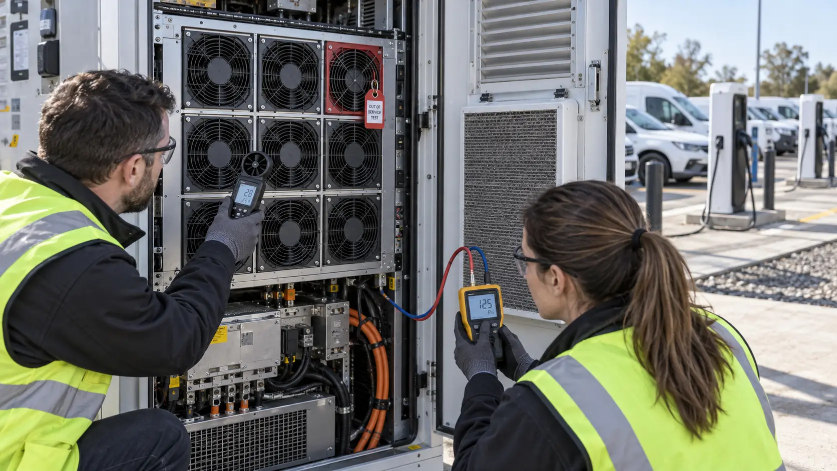
N+1 Was Written on the Drawing, but Not Proven in the Cabinet
A European fast-charger integrator had installed a redundant fan array. The design review still had one uncomfortable question: what happens to the air path when one fan stops?
An anonymized European EV-charger integrator was developing an outdoor power cabinet for repeated high-power charging. The cabinet used a compact DC axial fan array behind a filtered intake and a louvred exhaust. The first thermal build passed with every fan running, but the customer did not want to release the design on that test alone. A single fan failure could change the pressure balance of the entire array: the survivors would see a different duty point, while the stopped bay could become a low-resistance leakage path.
The project brief was therefore not 'supply more CFM'. It was: keep the protected power modules inside their thermal envelope after one fan is unavailable, keep the controller aware of the failure, and avoid a replacement fan that looks equivalent only on a catalogue page. The customer, product identity and released acceptance values remain confidential. This case records the validation method and the sample-development logic.
The Hook: A Spare Fan Can Still Steal Air
A stopped fan is not automatically a closed door.
In a parallel array, each fan contributes pressure to a shared plenum. If one fan stops, its impeller, guard and motor obstruction remain in the air path. Depending on the frame, clearance and pressure difference, air can leak through the failed bay or drive the stopped rotor backwards. That reverse path does not guarantee useful cooling through the power modules. It can reduce the pressure available to the active branches and make the surviving fans operate away from the point used for the original selection.
The same issue appears in other fan-array and power-cabinet designs: N+1 is a capacity statement, not a proof of path redundancy. The failed bay, isolation device, shared plenum, controller and power feed all belong in the test. A published fan-wall reference also warns that a stopped fan can become a reverse-flow or leakage path, while power-supply thermal guidance shows that neighboring fan paths can help or fight each other depending on pressure and direction. Those are engineering references, not MEGA customer measurements.
The customer wanted an answer that procurement could understand: not just 'the array has nine fans and needs eight', but 'with this exact cabinet resistance, filter condition, failed-bay hardware and controller response, eight survivors deliver the required duty'.
| Question | Weak evidence | Evidence used for release |
|---|---|---|
| Can survivors remove the heat? | Sum of free-air CFM | Survivor airflow at cabinet static pressure |
| Does the failed bay stay passive? | Fan alarm only | Reverse-flow, leakage and isolation measurement |
| Does the controller react? | RPM displayed on screen | FG/RD timing, alarm and derating action |
| Does the result survive field conditions? | Clean bench test | Filter, grille, hot ambient and loaded operating states |
Sample 01: Reconstruct the Heat Load and Air Path
The first sample did not start with fan replacement. It started with the cabinet's real losses and restrictions.
The integrator mapped the heat sources: power modules, inductors, busbars, connectors, control electronics and auxiliary supplies. Charger nameplate power was not used as cabinet heat load. A screening calculation used Q = P/(rho × cp × ΔT) to estimate airflow from heat loss and allowable air-temperature rise. For example, if measured cabinet loss were 6 kW, air density 1.18 kg/m³, cp 1005 J/(kg·K), and the permitted average air rise 12 K, the first estimate would be about 1,690 m³/h. That number is a sizing check, not a release value; local component limits and bypass can dominate.
The mechanical review then added filter, grille, heat-sink, cable and outlet losses. The fan sample was installed at the same cut-out, guard, gasket and spacing used by the customer. Pressure taps were placed before the filter, at the fan-array plenum and near the heat-sink inlet. This stopped the common mistake of comparing an open fan test with an obstructed charger cabinet.
The baseline matrix recorded supply voltage, PWM command, RPM, current, inlet temperature, pressure, airflow reference and the hottest power-module temperature. The same points were retained for the failed-fan tests.

Sample 02: Test One Fan Out at the Loaded Working Point
The failure test was run at the condition most likely to expose a weak margin, not at comfortable room temperature.
The customer first ran all fans at the normal charging load, then disabled one fan electrically while keeping the cabinet, filter and workload unchanged. The surviving fans were allowed to follow the approved controller response. The team recorded whether the stopped rotor spun backward, whether air short-circuited through the failed bay, and how the survivor operating points moved.
A useful engineering estimate explains why quantity alone is not enough. Suppose the cabinet needs 1,600 m³/h at 180 Pa and eight fans are required when operating. If each surviving fan delivers 200 m³/h only at 180 Pa in the installed path, eight fans meet the target. If the failed bay adds a leakage path that reduces the shared pressure to 145 Pa and each survivor then delivers 185 m³/h, the total is 1,480 m³/h, or 7.5% below the target. These values are illustrative; the project must replace them with the measured fan curve and system curve.
The sample review also checked whether the remaining fans saturated at maximum PWM. If they did, increasing command could raise noise and power without recovering the missing airflow. The correct next change might be a higher-static-pressure fan, a partition, a backdraft damper, a revised plenum, or a different fan spacing—not simply a higher RPM limit.
Sample 03: Add Isolation, Feedback and Derating Logic
The final design treated the fan as a monitored subsystem rather than a collection of independent motors.
MEGA Tech compared two failure-path options: a passive isolation detail that increased resistance through the stopped bay, and a controlled response that raised the surviving fan command while the cabinet reduced power if the thermal limit approached. The selected mechanical detail depended on pressure drop, service access, noise, contamination and the customer's safety review. No single damper or controller sequence was assumed to work universally.
Each fan supplied the interface agreed with the charger controller: voltage range, PWM behavior, FG speed feedback and the defined fault output where required. The controller test included a missing-FG event, an over-temperature trend, a restart after service and a low-voltage start. The point was to distinguish 'rotor is turning' from 'the cabinet is receiving the required cooling'.
The customer also checked common-mode failure domains. An N+1 fan array is not independent if all fans share one unprotected fuse, one connector, one controller output or one blocked intake. The final review therefore included branch wiring, start-up current, connector temperature and service replacement access.
| State | Fan-side evidence | Cabinet-side acceptance |
|---|---|---|
| All fans running | RPM, current, pressure, airflow | Normal thermal and acoustic envelope |
| One fan stopped | Survivor duty, failed-bay flow, alarm | Hottest component and derating response |
| Failed bay isolated | Pressure loss, leakage, service access | No unacceptable bypass or reverse rotation |
| Low voltage / restart | Start time, FG recovery, current | Controller recognizes valid recovery |
| Loaded filter / hot ambient | Available margin at worst state | No hidden loss of thermal limit |
Result: N+1 Became a Measurable Design Decision
The integrator received a fan configuration that could be quoted, sampled and approved against the actual cabinet instead of a slogan.
The final package linked the fan curve, cabinet resistance, failed-bay condition, controller response and thermal acceptance points. Procurement could compare a replacement fan by installed duty, feedback behavior, connector and sample result. The customer could also explain what must be re-tested if the filter, grille, fan spacing or power-module layout changes.
The valuable result was not a universal airflow or uptime claim. It was a controlled path from customer sample to production configuration: reproduce the cabinet, identify the failed-bay behavior, tune the fan and interface, then repeat the thermal test with the survivor count that the design actually permits.
For charger OEMs, this approach can reduce late-stage arguments between thermal, electrical, mechanical and purchasing teams. Each team sees the same evidence: where the pressure is spent, what a failed fan does to the air path, and which fan-side parameters MEGA Tech can customize before the next build.
How MEGA Tech Supports Custom EV-Charger Fan Arrays
MEGA Tech builds sample-ready cooling fans around the customer's cabinet, not around a free-air headline.
We can review custom DC axial fans and compact centrifugal blowers for power cabinets, including high-static-pressure behavior, frame and thickness, fan spacing, PWM response, FG/RD feedback, connector and cable routing, bearing option, environmental target and the installed noise boundary. Where a same-size replacement is requested, we still compare the operating point and failure behavior rather than promising equivalence from outline dimensions alone.
For a first review, provide heat loss by charging mode, required airflow at static pressure, filter and grille curves, ambient and altitude, voltage tolerance, PWM frequency and pinout, connector, fan envelope, N+1 definition, failed-bay hardware, acoustic target, life assumption and the acceptance method. A cabinet section, old fan sample or short commissioning video is often more useful than a catalogue link.
MEGA Tech can start with a small sample, tune the fan-side parameters around the customer's assembly and support the installed comparison. We do not supply the charger power modules, BMS, liquid loop, cabinet safety system or complete EVSE certification; those remain the customer's system-level responsibilities.
Engineer Questions About This EV Charger Case
These questions expose whether an N+1 claim is ready for design release.
Q: Does one extra fan automatically make the cabinet N+1? A: No. The survivors must carry the required duty at the installed pressure after the failed bay, controller and restrictions are included.
Q: Can a stopped fan simply be ignored? A: No. It can leak, rotate backwards or add a different obstruction. Measure or qualify the actual failed-bay path.
Q: Is FG feedback proof of cooling? A: No. It proves rotor-speed feedback. Pair it with pressure, airflow and component-temperature evidence.
Q: Should survivors always run at 100% after one failure? A: Not necessarily. The controller needs a validated response that considers pressure margin, noise, power, temperature and derating.
Q: What changes require a new N+1 test? A: Fan model, grille, filter, spacing, plenum, damper, controller logic, power feed, heat load or module layout can all change the result.
Q: Can MEGA Tech provide a small batch before production? A: Yes. Share the customer sample and installed duty so a custom fan or array configuration can be evaluated before volume release.
Questions for an EV-Charger Fan Design Review
Use this checklist before approving an N+1 fan array or replacement fan.
- What heat loss, ambient and altitude define the design duty?
- What airflow is required at the measured cabinet static pressure?
- What happens to the pressure curve when one fan is stopped?
- Can the failed bay leak or drive reverse rotation?
- Are fan branches, fuses, connectors and controller outputs independent enough for the intended redundancy?
- Does the survivor test include loaded filter, grille, heat sink and cable obstruction?
- What do PWM, FG and RD mean at startup, fault and recovery?
- Which component temperature is the acceptance limit, not just average exhaust temperature?
- What evidence must be repeated after a fan, filter, grille or plenum change?