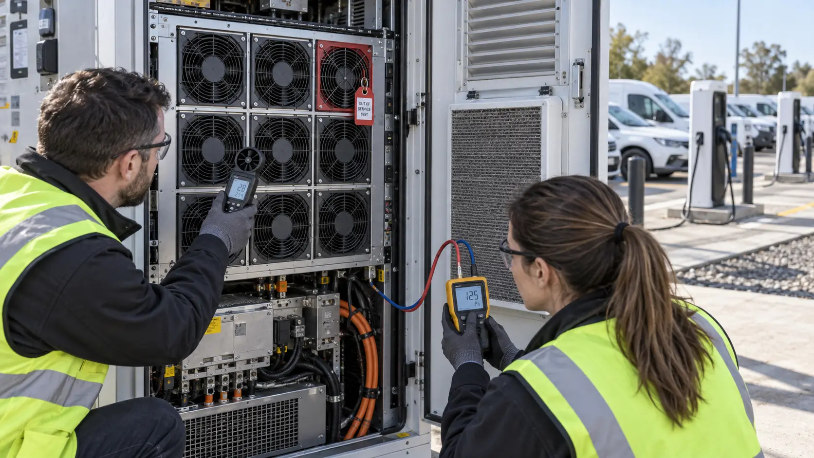
The Charger Worked in the Lab and Stalled at the Pilot Gate
An anonymised small EV-charger team needed a custom cooling fan while moving from a working prototype toward a repeatable pilot build.
The first charger enclosure was thermally acceptable on an open bench. The fan had room around its inlet, the heat source was easy to reach with a probe, and the test setup did not yet include the production grille, cable bundle, outlet restriction or service cover. When the team assembled a more representative enclosure, the result became less predictable: the same commanded speed did not guarantee the same useful airflow through the power electronics.
That transition is common in a small product team. The prototype proves that the concept can remove heat; the pilot build must prove that the fan, air path, connector, mounting and control interface can be assembled repeatedly. A fan selected only by free-air airflow can look adequate at the prototype stage and still lose margin when the enclosure adds resistance.
Customer identity and measured acceptance values remain confidential. This is an anonymised engineering path, not a claim about a named charger, a charger certification or a universal result. The purpose is to show what should be frozen before volume production is considered.
Start With the Charger Heat Duty, Not the Fan Name
The first design-review question is which operating state limits the charger, not which fan catalogue label looks closest.
A charger may have different heat states during standby, charging, load transition and recovery. The power stage, magnetics, control electronics and auxiliary supply can each create a different local temperature problem. If the team records only one enclosure temperature, it may miss the short state that actually consumes the thermal margin or the slow state that raises the steady temperature.
The review therefore listed the heat-producing components, their duty states, the intended inlet-temperature basis and the location of the thermal acceptance point. It also recorded whether the fan was expected to run continuously, follow a temperature command, respond to a PWM input or report FG/RD feedback to the charger controller.
This information does not need to be perfect on the first prototype. It does need to be explicit. An assumption such as ‘the fan will run at full speed’ should be marked as an assumption, then replaced by a measured operating point before the pilot specification is frozen.
The team separated heat generated by the charger from heat that arrived from the surrounding enclosure. A warm room, a nearby power device or recirculated exhaust can change the inlet condition without any change to the fan. Writing the temperature basis beside each thermal result made it possible to compare prototype, pilot and later service tests without implying that one room-temperature result covered every installation.
| Input | Why it matters | Evidence to keep |
|---|---|---|
| Heat load by state | Shows the limiting charger condition | Time-aligned electrical and thermal record |
| Inlet temperature | Sets the available cooling margin | Sensor position and ambient basis |
| Fan envelope | Constrains frame, thickness and outlet placement | Mechanical drawing and mounting condition |
| Control interface | Changes speed, feedback and fault handling | Voltage, PWM, FG/RD and connector record |
| Noise and environment | Prevents a thermal fix from creating a new field problem | Target, installation and exposure assumptions |
Measure the Installed Air Path Before Comparing Samples
The useful comparison is airflow at the charger operating pressure, not a free-air number copied from a catalogue.
The pilot enclosure introduced a grille, a bend, a heat sink, cable clearance, a cover and an outlet. Each item changed resistance or created an opportunity for bypass. The team mapped the intended route from inlet to heat source to outlet, then identified where pressure and temperature should be measured. A fan that spins at the expected speed can still deliver too little air through the heat source if the air chooses an easier bypass route.
The sample review compared candidate fan P-Q behavior with the installed system resistance. Where the path turned sharply or became restrictive, a compact centrifugal blower could be considered alongside an axial fan. Where the path was short and direct, an axial fan could be simpler. The selection remained conditional on the real envelope, voltage, control, noise, mounting and measured operating point.
The team also checked hot-air recirculation. A gap around the cover or outlet can return discharged air to the inlet and make the fan appear undersized. Seals, service panels and neighboring components were therefore included when the pilot air path was reviewed.
Pressure taps or equivalent measurement points were chosen before the sample test, not after a disappointing result. The record stated whether pressure was measured across the fan, across the heat source, or across a defined section of the enclosure. That detail matters because two teams can use the word pressure while measuring different boundaries. The air volume should also be stated at the same reference condition used in the comparison.
Use the First Sample to Find the Real Constraint
The first sample is a measurement tool: it should reveal whether the next change belongs to the fan, the duct, the heat sink or the control schedule.
The first sample used the intended mounting position and a representative connector and harness. The team logged fan voltage at the connector, current, command, actual RPM or feedback, inlet temperature, heat-source temperature and the defined airflow or pressure point. This separated a fan problem from a voltage-drop problem and a thermal-interface problem from an air-path problem.
If the heat source remained hot while the fan reached its expected speed, the next check was useful airflow through the heat sink and outlet. If airflow was present but the temperature remained high, the heat sink or interface required review. If the fan did not reach the expected state, the team checked supply tolerance, controller timing, connector behavior and the low-speed start region before requesting a larger fan.
The sample was not treated as a production promise. It was a controlled way to learn which variables mattered. A second sample or a mechanical revision was considered only after the first test record made the failure mode visible.
For a small team, this approach protects both engineering time and purchasing decisions. If the problem is a blocked grille, buying a higher-speed fan can hide the cause while adding noise and current. If the problem is a weak mounting surface, changing the impeller may not solve the vibration. The sample review is most valuable when every proposed change has a stated hypothesis and a measurement that could prove it wrong.

Tune Noise, Vibration and Control With the Thermal Result
A higher command is not automatically a better charger solution if it adds noise or vibration without increasing useful heat removal.
The prototype team checked PWM behavior across the intended supply tolerance rather than treating a command percentage as a universal RPM. The low-speed region was reviewed for reliable startup and stable running. The high-speed region was reviewed for current, acoustic tone, vibration and thermal benefit. The controller record identified what it considered a valid FG or RD signal and what it did when the signal was absent.
Mounting changed the result as well. Fastener preload, frame distortion, elastomer support, connector latch and cable exit were checked in the enclosure. A cable touching a cover can create a vibration path; a grille or bracket can shift the acoustic character; a small gap can create bypass. These are pilot-build issues, not details to postpone until after production tooling or a large purchase.
The engineering boundary remained clear: the fan-side sample can be adjusted and measured, while charger control logic, electrical safety, EMC and system-level fault response belong to the charger team and system integrators.
The acoustic check used the finished enclosure position rather than an isolated fan on a table. The microphone or acceptance position, operating state and surrounding panels were recorded. Tonal noise can be created or amplified by a grille, a cavity or a mounting panel, so a lower free-air sound figure does not automatically mean a quieter charger. The project kept thermal, electrical and acoustic observations in the same test record.
When the charger is intended for more than one installation, the review also records which assumptions are common and which are site-specific. A wall-mounted enclosure, a cabinet installation and a service-bench setup may have different clearances and discharge paths. The fan sample can be the same, but the installed operating point still needs to be stated for each relevant configuration.
| Check | Failure if missed | Pilot evidence |
|---|---|---|
| Connector and voltage | Startup or feedback becomes intermittent | Voltage at fan pins and contact inspection |
| PWM and actual RPM | Command does not represent installed cooling | Command, speed and airflow trace |
| Mount and harness | Vibration or bypass changes after assembly | Clearance, retention and installed inspection |
| Noise at the user position | Thermal fix creates an acoustic complaint | Defined microphone position and operating state |
| Fault response | Fan alarm has no clear system action | Controller decision and recovery record |
Build the Pilot Around Repeatable Assembly
Pilot production changes the question from ‘does this sample work?’ to ‘does the same result survive the next build?’
The pilot build used the intended fasteners, connector, harness route, grille, gasket, cover and service sequence. The team recorded which details affected the inlet and outlet. If an operator could install the fan in more than one orientation, the work instruction needed a clear orientation check. If cable length changed the mount or bypass, the harness specification needed to be controlled rather than left as a drawing note.
A small build also exposes variation that a single prototype hides. The inspection plan included connector seating, frame clearance, fastener condition, grille blockage, gasket position and cable retention. Thermal and airflow checks were repeated on representative builds so the project could distinguish a fan design change from an assembly variation.
The objective was not to create an unnecessarily heavy inspection process. It was to identify the few assembly details that could move the operating point. Those details became part of the pilot record and the production specification.
The pilot team also considered service replacement. A replacement fan should fit without forcing the frame, pinching the harness or changing the intended clearance. The connector keying, cable exit and mounting orientation were therefore treated as functional details. If the customer later changes a supplier, the comparison must use the same installed boundary rather than relying on outline dimensions alone.
Freeze the Specification Only After the Change Boundary Is Clear
A volume-release specification should say what was tested and what change would require another sample.
The release record captured the required airflow and static pressure at the installed point, fan envelope, supply tolerance, current, control interface, connector, cable exit, mounting, noise target, temperature and environment. It also recorded the thermal sensor location, the load state and the assembly condition used for the result.
The team then identified triggers for revalidation. A new grille, duct, heat sink, cover, controller schedule, connector, cable route or mounting bracket could change the result even if the fan frame remained the same. Treating these as known change triggers made the production handoff more honest and more useful than declaring a permanent equivalent replacement from outline dimensions.
The final decision was therefore a controlled release boundary: which fan configuration, installed path and operating states were represented, which evidence supported them, and which future changes would reopen the review.
This record also gave procurement a practical handoff. It identified the configuration to request, the information that must stay unchanged during the pilot, and the conditions under which a new sample review was required. That is especially useful for a small company where one person may be covering thermal design, purchasing, assembly and customer support. A clear boundary prevents a production substitution from being mistaken for an engineering approval.
The same discipline helps when a sample is requested for another voltage or control interface. The new request should identify what is changing and what is staying fixed. A different voltage, connector, control reference or speed range can change current, startup behavior, noise and useful pressure. It should be treated as a new sample question even when the frame envelope is unchanged.
How MEGA Tech Supports EV-Charger Fan Development
MEGA Tech helps small product teams move from a cooling requirement to a fan sample that can be evaluated on the real charger assembly.
MEGA Tech develops and manufactures custom cooling fans, from fan selection and air-path review through sample validation and volume production. We can review DC axial fan and centrifugal blower options against the installed airflow and static-pressure requirement rather than selecting by a part number or free-air value alone.
For a first review, send the charger heat load by state, inlet temperature and pressure basis, required airflow and static pressure, fan envelope, voltage tolerance, PWM/FG/RD or alarm interface, connector and harness, mounting, noise and vibration target, environment, quantity and life assumption. A representative enclosure or clear air-path drawing helps turn a catalogue discussion into a useful sample review.
MEGA Tech is the custom cooling-fan manufacturer. Complete EV chargers, cabinets, coils, liquid loops, controllers, electrical safety and system certification remain the responsibility of the charger manufacturer and system integrators. Start with the fan selection tool, review the DC axial fan range, or request a sample on WhatsApp.
A useful first message does not need to be a polished specification. A photograph or drawing of the air path, the available fan envelope, the supply range, the target operating state and the quantity stage can be enough to start a technical review. If a P-Q curve, noise target or environmental condition is already available, include it. The goal is to align the sample with the real charger constraints before a decision is made.
Engineer FAQ
These questions usually decide whether an EV-charger fan sample is ready for pilot production.
Q: Is free-air airflow enough to select a charger fan? A: No. The installed grille, heat source, duct, cover and outlet define the operating pressure.
Q: Should the team increase speed when the charger runs hot? A: First confirm useful airflow, bypass, inlet temperature, heat-sink contact and the actual operating point.
Q: Does a successful prototype prove pilot readiness? A: No. Repeat the result with the intended connector, harness, mount, grille, cover and assembly method.
Q: Does the fan supplier own charger safety or certification? A: No. MEGA provides fan-side development and sample evidence; the charger team owns system qualification.
Q: What does MEGA Tech need for a first sample? A: Heat load, airflow and pressure, temperature, envelope, voltage, control, connector, mount, noise, environment, quantity and the real assembly.
Questions for an EV-Charger Fan Design Review
Use this checklist with thermal, mechanical, electrical, controls, manufacturing and procurement teams.
- Which charger heat state defines the limiting thermal margin?
- What airflow and static pressure are required at the installed air path?
- Where are the inlet, heat-source and outlet temperatures measured?
- What voltage tolerance and harness drop exist at startup and steady operation?
- What PWM, FG/RD or alarm behavior defines a valid fan state?
- Can the grille, duct, cover, cable or gasket create restriction, bypass or recirculation?
- What connector, mounting and cable-route details must be repeated in every pilot build?
- What noise and vibration measurement point represents the finished charger?
- Which change triggers a new sample: fan, grille, duct, heat sink, cover, controller or mount?
- What exact information should be sent with the sample request: size, voltage, airflow, pressure, quantity and environment?