The Payload Was Cool on the Bench and Hot in the Mission Profile
An anonymized European UAV developer needed a compact cooling fan for an inspection payload that changed from idle to sustained processing during flight.
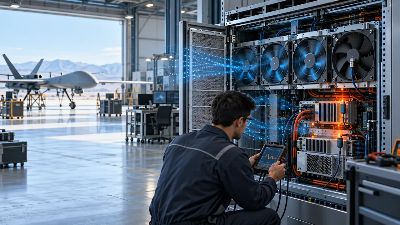
The payload combined a camera, processor, power conversion and storage electronics inside a tight enclosure. The prototype passed a short laboratory check, but the customer saw the temperature rise during a longer mission profile. The fan was turning, yet part of the air was taking an easier path around the heat source. Vibration from the airframe and the changing air density at altitude added uncertainty to the original selection.
The question was not simply which 40 mm fan had the highest free-air CFM. The team needed to balance mass, electrical power, installed pressure, airflow distribution, vibration, startup, altitude basis and the response to a fan fault. The customer and released values remain confidential; this case describes the engineering workflow.
Why UAV Cooling Is a Different Fan Problem
A drone fan has less mass and power budget, but more changing conditions than a stationary enclosure.
Active cooling adds useful forced convection, but it also adds mass, battery consumption and a fan failure mode. A published UAV thermal review describes these trade-offs directly, while experimental work on UAV equipment boxes shows that payload cooling can be a transient problem rather than a single steady operating point. The fan must therefore be selected for the mission duty, not only the laboratory snapshot.
Altitude changes density and therefore the mass flow and heat capacity delivered by a given volumetric airflow. Vibration can change clearances, mounting transmission and connector reliability. Propeller wash or forward-flight flow can help one installation and bypass another. A sealed payload bay can receive almost no useful external airflow even when the airframe is moving quickly.
The customer wanted a sample that could be tested under representative vibration and thermal states before the mechanical design was frozen. That made the project suitable for MEGA Tech's small-batch customization process.
| Constraint | Wrong shortcut | Engineering input |
|---|---|---|
| Mass and battery | Choose the smallest fan | Fan mass, electrical power and mission duration |
| Altitude | Use sea-level CFM | Air density and pressure basis |
| Vibration | Treat the fan as a static part | Mounting, clearance and endurance profile |
| Payload heat | Use average enclosure temperature | Hotspot location and transient load |
| Failure | Assume the aircraft will be fine | FG/RD, derating or mission-abort strategy |
Sample 01: Map the Payload Air Path Before Changing RPM
The first revision was a mechanical airflow correction, not a larger motor.
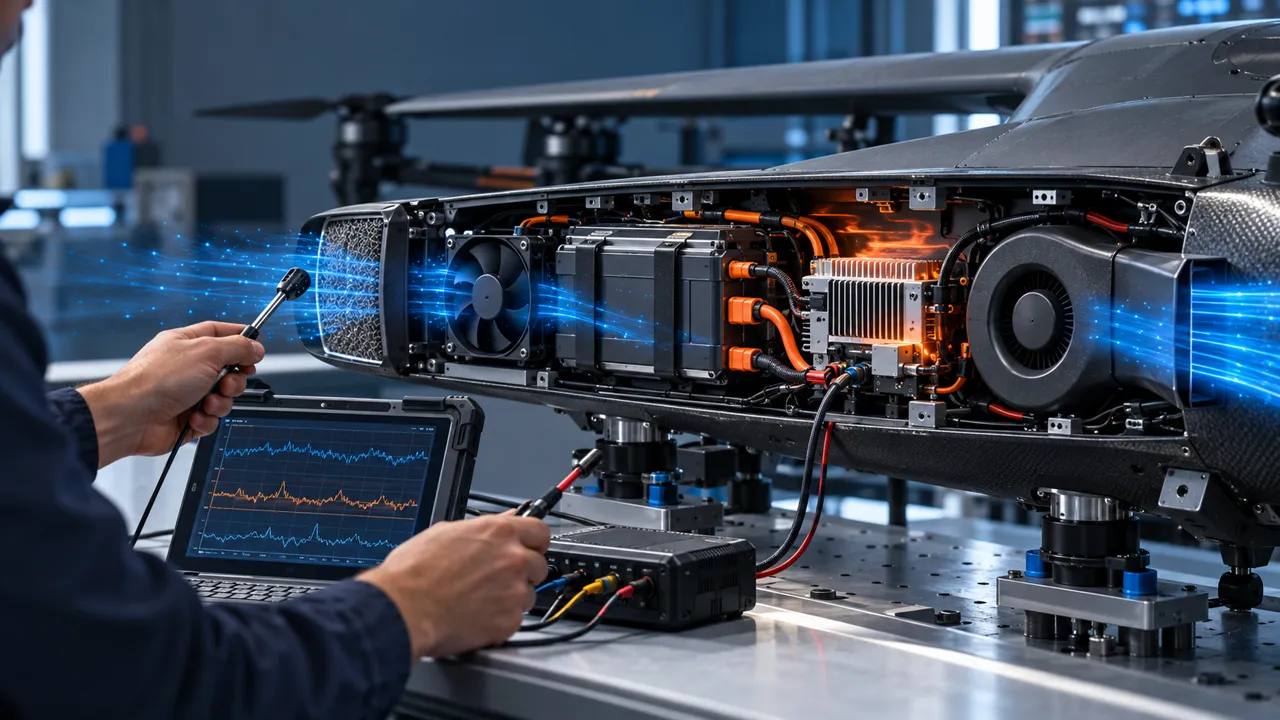
MEGA Tech received the customer's payload sample, fan cut-out, duct, filter or grille, heat sink and cable route. The team checked whether the fan discharge actually crossed the processor and power devices or escaped through a clearance around the board. A small bypass can dominate a compact enclosure because the intended channel is often narrow and restrictive.
A screening calculation connected heat load to airflow. If a payload dissipates 12 W and the air-side model assumes 1.2 kJ/(m³·K) with a 10 K average rise, the ideal flow estimate is about 0.01 m³/s, or 21 CFM. That is only a first check: altitude, heat-sink resistance, recirculation and local hotspots can make the required installed flow different.
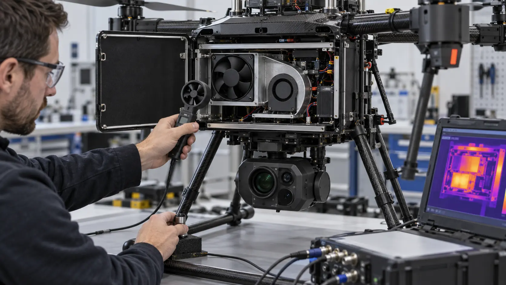
The sample was then tested with the real duct and an airflow probe near the heat source. The team recorded voltage, current, PWM, RPM, pressure and hotspot temperature rather than treating normal RPM as proof of useful cooling.

Sample 02: Tune the Fan Around Weight and Installed Pressure
The candidate was chosen at the real operating point, then adjusted instead of simply running faster.
The customer compared a compact axial fan and a small centrifugal blower because the payload duct had a turning section and a narrow outlet. The selection considered installed pressure, not just free-air flow. A blower can be useful in a restrictive path, while an axial fan can be more efficient in a short open path; the correct answer depends on the measured system curve.
The team also calculated the battery cost of cooling. If a fan consumes 1.2 W for a 45-minute mission, it uses 0.9 Wh in that mission before converter losses. That may be acceptable or unacceptable depending on the aircraft's total energy budget. The number is an estimate to expose the trade-off, not a claim about a specific UAV.
MEGA Tech adjusted the sample's PWM response, connector and cable exit around the customer's controller and available supply. The target was stable startup, enough pressure margin and a usable low-noise command, while keeping the fan small enough for the payload envelope.
Sample 03: Repeat the Mission Profile With Vibration and Altitude Basis
The sample was not accepted from a room-temperature bench test.
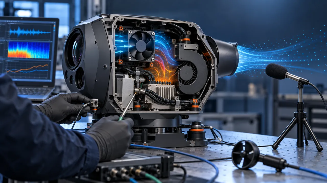
The customer repeated idle, processing and peak payload states while applying the agreed vibration profile to the payload mount. The test checked fan startup, speed feedback, current, noise, mounting movement, connector retention and the hottest component. If the application used a defined altitude, the airflow and thermal calculation were corrected to that density basis or tested in a chamber where practical.
The acceptance decision remained project-specific. A fan with a good bench result could fail the payload test if the mounting transferred vibration into the frame, if the cable touched the impeller guard, if the inlet filter added unexpected resistance or if the controller command was too low to start reliably at reduced voltage.
The fan failure path was also discussed. Depending on the payload and mission, the response might be an FG/RD alarm, a reduced processor power limit, a graceful payload shutdown or a return-to-launch decision. The cooling fan is not a substitute for the aircraft's flight-safety analysis.
Result: The Customer Received a Tuned Payload Sample, Not a Catalogue Swap
The final configuration was defined by the payload's mission conditions and mounting, so the next prototype could be built with fewer unknowns.
The project package recorded the fan envelope, mass, voltage, PWM and FG behavior, installed pressure, airflow reference, hotspot temperature, vibration condition and mission-state response. The customer could now see which changes would trigger another validation: a new duct, heat source, fan orientation, altitude range, connector, mounting isolator or control limit.
The transferable lesson is simple: UAV cooling is a coupled mass, power, airflow and reliability problem. A smaller fan is not automatically better, and a higher CFM number is not automatically useful. The best sample is the one that puts air through the heat source while respecting the aircraft's energy and vibration limits.
MEGA Tech supported the project from the customer's physical sample, through fan and interface adjustment, to the installed comparison. That is the path we recommend for startups and established UAV teams that need a small first build before production.
How MEGA Tech Supports Custom UAV Cooling Fans
We help UAV teams turn a tight payload envelope into a sample that can be tested on the real airframe.
MEGA Tech can review compact custom DC axial fans and centrifugal blowers for payload bays, avionics, camera systems, processors and power electronics. The review can include frame and thickness, pressure and airflow, PWM, FG/RD, connector, cable routing, bearing option, vibration concern, temperature range, mass and the customer's production quantity.
For a first review, send the payload sample or 3D section, heat load by mission phase, inlet temperature and altitude, airflow path, pressure estimate, fan envelope, voltage tolerance, control interface, vibration condition, acoustic target, life assumption and failure response. We can start with a small sample, tune the fan-side parameters and return a configuration for installed testing.
We do not certify the complete UAV, battery, flight controller, airframe or mission safety function. Those responsibilities remain with the aircraft and payload manufacturer.
Engineer Questions About This UAV Cooling Case
Use these questions before freezing a fan inside a flight payload.
Q: Is free-air CFM enough for a drone payload? A: No. The duct, grille, heat sink, cable path and altitude determine the installed operating point.
Q: Why can the fan spin normally while the payload stays hot? A: Air can bypass the processor or power device, or the system curve can move the fan to a lower-flow point.
Q: Does a larger fan always improve the aircraft? A: Not necessarily. Mass, power, mounting and vibration can offset the thermal benefit.
Q: Should the fan run continuously? A: It depends on mission duty, condensation and control requirements. Validate startup, minimum command and the full temperature sequence.
Q: What does MEGA Tech need for a first sample? A: The payload sample, heat load, altitude, airflow path, voltage, control interface, vibration condition, fan envelope and quantity.
Questions for a UAV Fan Design Review
A compact checklist for thermal, mechanical, electrical and procurement teams.
- What is the heat load during hover, cruise, processing and peak payload operation?
- What airflow and pressure are required at the actual duct and altitude?
- Where is the intended flow path, and what bypass path is easier?
- What mass and electrical power can the mission budget accept?
- How will vibration, shock, connector retention and clearance be tested?
- What does FG/RD report and what does the aircraft do after a fan fault?
- Are startup and low-voltage conditions validated on the actual supply?
- Which changes require a new sample test: duct, mount, heat source, fan or control?