The Customer Sample Was the Starting Point
A UAV electronics team did not need a catalogue fan in isolation. It needed a cooling assembly that fit its payload enclosure, vibration environment, power budget and flight mission.
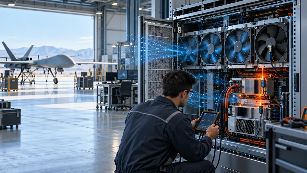
The customer arrived with an early payload-electronics sample: a compact enclosure containing a processor board, power conversion, sensor electronics and a small heat sink. The available space was already fixed by the airframe and payload bracket. The first prototype used a small fan, but the team could not confidently connect the fan setting to the temperature margin during the mission profile. On the bench, the air looked acceptable; inside the installed sample, the hottest component did not receive the same airflow.
This is a common UAV cooling problem. The electronics may see transient power during take-off, hover, transmission or image processing, while the available fan supply comes from a battery-derived rail with voltage variation. The enclosure may have a narrow inlet, a filter or grille, a short duct and an outlet near a bracket. Vibration and shock can alter clearances and create noise. Weight and acoustic signature also matter, especially for inspection, mapping and public-safety missions.
MEGA Tech treated the customer's physical sample as the first test fixture. Instead of choosing a fan from maximum CFM, the team documented the real envelope, pressure path, command interface, thermal load, noise target and motion-related constraints before changing the design.
What the UAV Engineers Needed to Control
The cooling requirement was defined as a set of linked constraints rather than one airflow headline.
The first constraint was heat load. The team separated average power from short-duration peaks and identified which component needed the earliest protection. An illustrative planning case used a 9 W average electronics load with a 14 W peak during a processing burst. The numbers are representative test-planning values, not a customer result or a universal UAV requirement. The important step was to define when the peak occurred and how long the fan had to respond.
The second constraint was the installed pressure path. The inlet grille and internal guide occupied part of the compact opening, while the heat sink fins and outlet transition added resistance. A fan with a higher free-air CFM could still deliver less useful air than a lower-speed sample with a better match to the system curve. The third constraint was power. A fan that draws additional current from a small battery rail can reduce mission endurance or disturb the converter margin.
The team also set practical mechanical and acoustic constraints: mounting-hole location, thickness, cable exit, vibration direction, minimum startup voltage, PWM or voltage control, FG or RD feedback, and the noise level acceptable near the payload. These details are why a custom sample review is often more efficient than trying to force a catalogue part into an existing airframe.
| Requirement | What was recorded | Why it changed the sample |
|---|---|---|
| Thermal load | average, peak, duration and protected component | defines the response and temperature margin |
| Air path | inlet, grille, heat sink, outlet and pressure points | sets the real operating point |
| Electrical | rail range, PWM/voltage command, current and feedback | prevents a fan-interface mismatch |
| Mechanical | envelope, mount, cable exit and clearance | keeps the sample inside the airframe |
| Motion environment | vibration, tilt, shock and mission phases | exposes contact, resonance and transient faults |
| Acoustics | measurement point and mission noise target | prevents a thermal fix that creates an acoustic problem |
Sample 01: The Fan Was Not the Only Problem
The baseline sample showed why a free-air test and a real payload test can tell different stories.
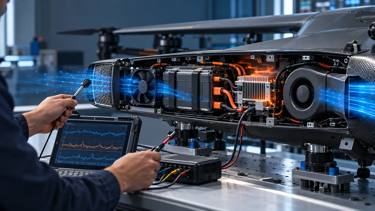
The first sample was tested at the customer's nominal voltage with the original bracket and heat sink. The fan reached its expected speed, but the downstream temperature map was uneven. Air bypassed the intended fin channel and a nearby wall disturbed the inlet. During vibration, the bracket introduced a narrowband sound that was not present on the static bench. The team therefore separated three issues: insufficient flow at the load, poor flow distribution and motion-related mechanical noise.
A planning calculation helped frame the next test. If 9 W of heat must be rejected with a 22 °C allowed rise, the required average heat-transfer path is not defined by CFM alone. The team must know the heat sink resistance, contact condition, air temperature and the portion of flow that actually crosses the fins. The sample was not rejected because its datasheet number was low; it was revised because the installed result did not meet the intended thermal map.
MEGA Tech recorded the fan voltage, command, RPM, current, inlet and outlet temperature, local component temperatures, mounting condition and sound at the same fixture. This created a repeatable baseline for the next revision instead of relying on a subjective flight-test impression.
Sample 02: Tune the Fan, Guide and Control Together
The second revision changed the installed system, not only the motor speed.
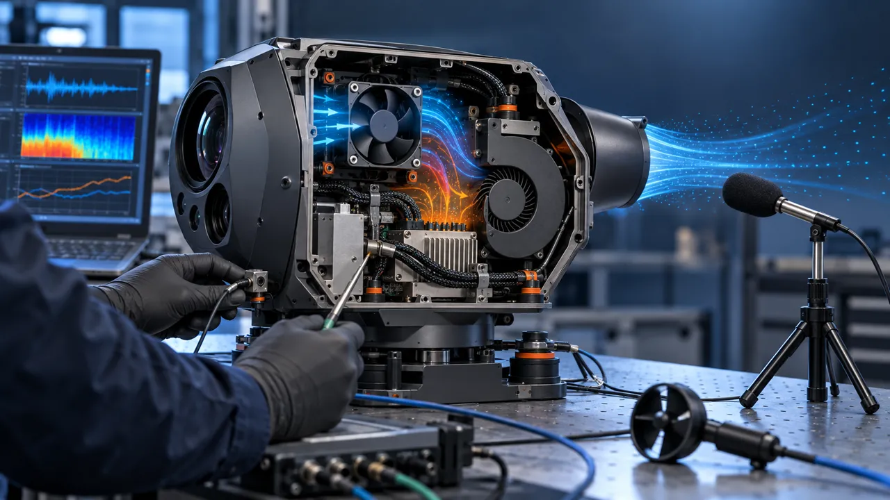
The sample was adjusted around the customer's available space. The outlet guide was refined to reduce bypass, the mounting interface was checked for bracket contact, and the control curve was adjusted so the fan did not jump immediately to an unnecessarily high speed during low-load operation. The objective was to place the fan at a useful operating point with enough headroom for the peak load, while avoiding a high-speed acoustic penalty when the payload was idle.
The team compared two control strategies. In the first, a fixed command produced stable airflow but wasted power during the low-load phase. In the second, the command followed the measured thermal state with a defined minimum speed and hysteresis. The final choice depended on the customer's controller and risk analysis; MEGA Tech supplied the fan-side response and sample behavior rather than assuming that any PWM signal would be compatible.
A practical comparison recorded the same five states: idle, nominal processing, peak processing, warm enclosure and post-vibration restart. Each state included current, RPM, pressure or airflow proxy, protected temperature and noise. If one state improved while another lost margin, the sample was not considered finished. The point of customization was to converge the complete set of constraints.

Sample 03: Validate the Motion and the Mission Profile
A UAV cooling sample must survive the conditions that make the product move, not only the conditions of a quiet bench.
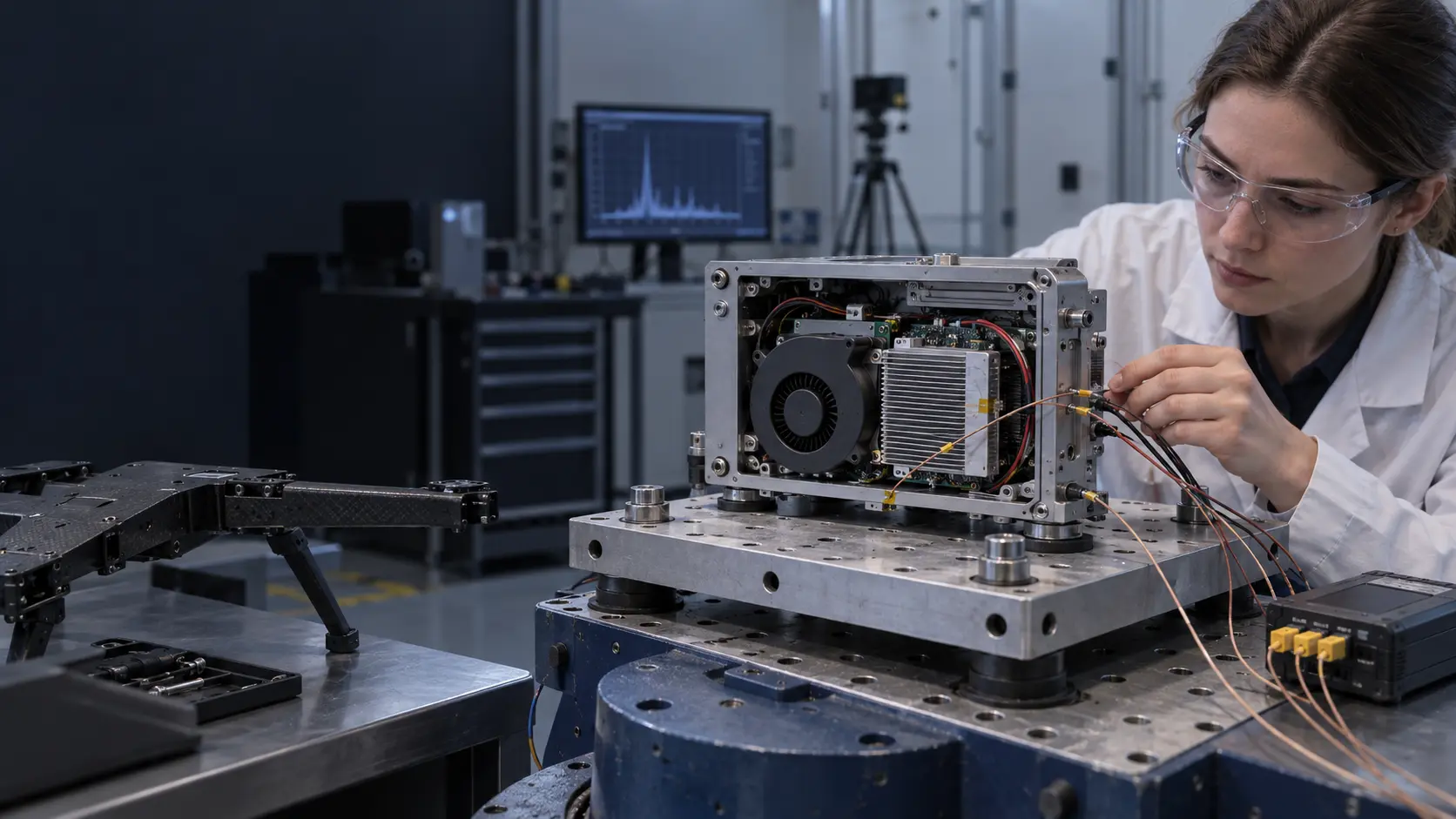
The customer then repeated the test with the actual bracket and representative motion conditions. The aim was not to claim that a laboratory shaker equals every flight environment. It was to expose the failure modes that a stationary fan test cannot see: cable movement, bracket flex, impeller-to-housing clearance, connector retention, resonance, changing inlet direction and the transition between mission phases.
The validation sequence included power-on at the minimum declared voltage, steady nominal operation, a peak processing interval, controlled vibration, tilt, a rapid command change and warm restart. The team checked for abnormal noise, contact, startup failure, feedback dropout, current spikes and protected-component temperature. The sample was also compared with the original fan at the same installed condition so the customer could distinguish a genuine improvement from a changed test setup.
The final evidence was a test record tied to the sample revision. It listed the part configuration, mounting, voltage, command, measurement points and acceptance limits. This matters for production: a fan that works in a hand-held prototype is not yet a production design until the critical interface and test condition can be repeated.
The Result Was a Transferable Sample Process
The customer did not receive a promise that one catalogue model would fit every UAV. It received a repeatable path from a real sample to a controlled fan configuration.
The outcome of the project was a candidate cooling assembly that matched the customer-defined envelope and interface more closely, with a documented installed test method. The exact approved values remain project-specific. The transferable result is the process: start with the sample, identify the real heat and pressure problem, revise the geometry and fan behavior, test across mission states, and freeze the evidence that production must repeat.
This approach also protects the customer from a common procurement mistake. A replacement fan with the same outline dimensions is not automatically equivalent. Bearing type, blade geometry, PWM response, startup behavior, connector, cable exit, pressure curve, vibration behavior and noise can all change the UAV system. The correct comparison is the operating condition and the sample result, not only the frame label.
For early-stage companies, the process can begin with a small first build. The customer does not need to commit to a large production order before the thermal path is understood. A sample can be modified, evaluated, and then converted into a controlled production specification once the application owner has approved the result. This is where MEGA Tech's custom development model is useful.
What MEGA Tech Can Customize for UAV Cooling
MEGA Tech works with the customer requirement and physical sample, not only with a catalogue replacement request.
MEGA Tech can review compact DC axial fans and centrifugal blowers for UAV payload electronics, gimbal electronics, communication modules, flight-control enclosures and other moving platforms. The review can include frame and thickness, airflow direction, pressure/airflow duty, connector and cable, PWM or voltage control, FG or RD feedback, bearing configuration, startup behavior, mounting and sample-level adjustments.
For the first review, provide the heat load and peak duration, required airflow at static pressure, inlet temperature and altitude basis, supply voltage range, control interface, envelope, mounting drawing, cable route, noise target, vibration or shock conditions, duty cycle and life assumption. A current fan part number is useful, but the installed working point and the problem observed on the customer's sample are more useful.
We can accompany the customer through sample revisions and provide fan-side data for the declared test states. We do not supply the UAV flight controller, propulsion system, battery pack, flight-safety software, airframe certification or mission approval. The UAV manufacturer owns the final thermal, vibration, flight-safety and regulatory validation.
Engineer Questions About This UAV Case
The case is useful when the next sample is defined with measurable questions.
Q: Why not choose the highest-CFM fan that fits? A: Because the installed grille, heat sink, duct and outlet determine the operating point. Free-air CFM does not prove airflow through the UAV payload.
Q: What did MEGA Tech adjust? A: The sample review can adjust fan format, pressure/airflow duty, control response, mounting, cable interface and airflow guide around the customer's actual enclosure. The exact change depends on measured evidence.
Q: How do you handle a small first build? A: Start with the customer's sample and a declared test record, revise the fan or interface, and build a small evaluation quantity before the production specification is frozen.
Q: What must be tested during movement? A: Clearance, bracket support, cable retention, vibration, tilt, startup, feedback, current, noise, pressure/airflow and protected temperatures.
Q: Can a custom sample be called a certified UAV solution? A: No. MEGA Tech can support fan development and sample validation; the UAV maker owns airframe, flight, safety and regulatory approval.
Questions for a UAV Cooling Sample Review
Use this checklist before asking for a fan quotation or approving a prototype.
- What heat load is average, what is peak, and how long does the peak last?
- Which component is the thermal bottleneck, and where is its temperature measured?
- What airflow and static pressure are required at the actual grille, heat sink and outlet?
- What voltage range and control signal are available during the full battery condition?
- What are the mass, thickness, mounting, cable exit and clearance limits?
- What vibration, shock, tilt and mission transitions must the sample reproduce?
- What noise or acoustic signature is acceptable near the payload?
- Is FG or RD required, and what does the controller do after a fan fault?
- Will the candidate be tested on the customer's real bracket and enclosure?
- Which measured conditions will be frozen in the production specification?