The problem in operation
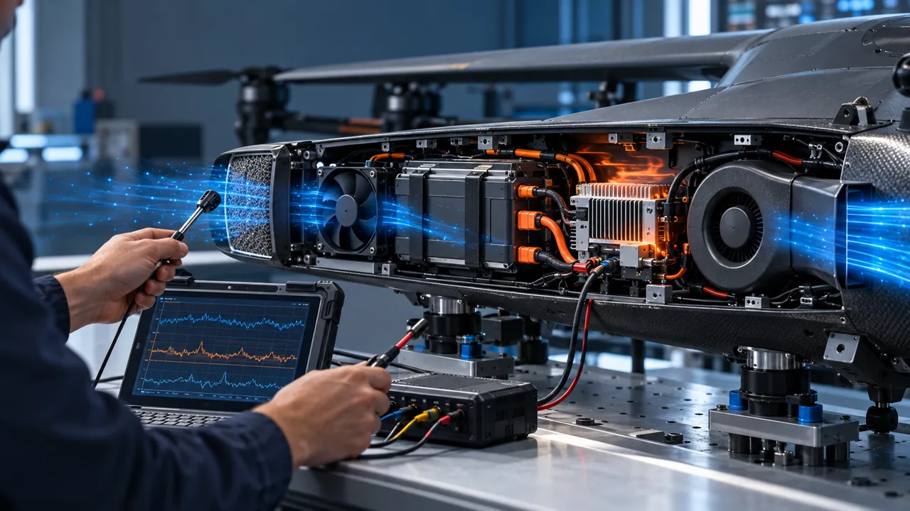
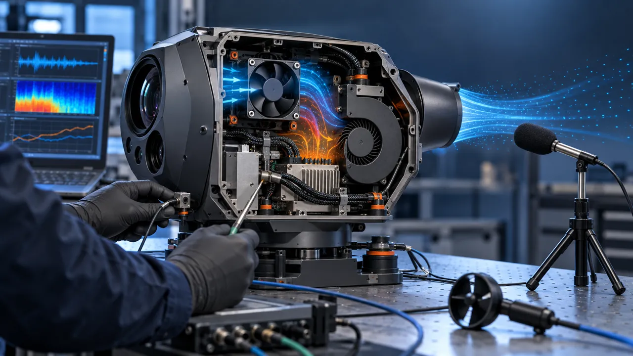
A 45×45×10 mm centrifugal blower used in a drone application produced abnormal noise under movement and vibration. The issue was traced to a small impeller overhang beyond the housing that allowed intermittent contact with surrounding parts. Because the sound appeared during motion rather than at rest, the investigation had to cover mechanical clearance, vibration and the installed airflow path together.
- Issue appeared under vibration rather than at rest.
- The contact risk created noise and a long-term reliability concern.
- Electrical performance still needed to match the original integration.
Mechanical redesign
The blower was redesigned with the impeller fully enclosed inside the frame. The purpose was to remove the contact path mechanically, rather than create a new electronics problem for the customer. The revised sample was then checked against the original electrical interface and the application requirements instead of treating the enclosure change as an isolated cosmetic revision.
- Fully enclosed impeller layout.
- Original current and speed performance retained according to the published case.
- Multi-directional shake testing used to check for abnormal contact.
- Clearance, outlet restriction, mounting support and cable routing reviewed as part of the assembly.
What engineers should validate in a compact blower
A clearance fix is successful only if it removes contact without creating excessive pressure loss, recirculation, heat or power demand. AMCA guidance notes that inlet and outlet obstructions can create system effect, while NASA cooling-fan research shows that inlet geometry and tip clearance can materially affect pressure rise and stable operating range. For a drone or other moving platform, the validation setup should therefore reproduce the real bracket, nearby walls, outlet transition and vibration direction where practical.
- Measure impeller-to-housing clearance over the full rotation, not only at one clock position.
- Check contact risk during vibration, shock, tilt and cable or bracket loading.
- Compare airflow and static pressure at the same voltage and installed resistance.
- Record current, speed, noise and component temperature before and after the redesign.
- Confirm that the revised outlet and inlet do not trade a mechanical noise problem for an airflow problem.
Result and transferable lesson
The published case reports no abnormal noise or contact in the redesigned configuration. It demonstrates that small dimensional details can have a major effect on the reliability of compact blowers in motion-sensitive equipment. The result is project-specific: the approved configuration still needs to be checked against the customer's required airflow, pressure, noise, temperature and endurance conditions.
- Application: drone cooling.
- Product format: 45×45×10 mm centrifugal blower.
- Primary fix: housing and impeller clearance control.
- Acceptance focus: no contact under movement, with electrical and thermal performance retained.
From a clearance issue to a production-ready sample
For a compact product, MEGA Tech can review the mechanical envelope and cooling requirement together, modify the blower housing or impeller arrangement, and build samples for evaluation. The sample review should include the actual mounting bracket and air path so the customer can decide on noise, thermal and reliability performance before committing to a larger build.
Once the design is approved, the critical dimensions and test conditions can be transferred into a controlled production specification. That can include clearance limits, visual or gauge checks, electrical operating limits, vibration or contact screening and the required airflow or pressure confirmation for the finished assembly.
- Review drawings, available space, vibration direction and airflow resistance.
- Modify the fan or blower around the customer's real mechanical interface.
- Build and test samples before finalizing the production configuration.
- Freeze critical clearance dimensions and repeatable inspection points for volume production.
Engineer Questions About This Case
A compact blower can create a mechanical failure mode when clearance, vibration and airflow are reviewed separately.
Q: What caused the abnormal noise? A: A 45 x 45 x 10 mm centrifugal blower had a small impeller overhang that could contact nearby parts during movement and vibration. The issue was not visible in a stationary check alone.
Q: Why redesign the housing instead of changing the electronics? A: The evidence pointed to a mechanical contact path. Enclosing the impeller inside the frame removed that path while preserving the customer electrical interface for evaluation.
Q: What can a clearance change affect? A: It can change pressure loss, recirculation, noise, power and thermal loading. The revised geometry must therefore be checked against the real bracket, walls, outlet transition and vibration condition.
Q: How should a compact blower sample be validated? A: Reproduce the mounting envelope and motion-related vibration where practical, then record contact or noise behavior together with airflow, pressure, power and temperature.
Q: What should be frozen for production? A: Critical clearance dimensions, mounting conditions, electrical limits, vibration or contact screening and the required airflow or pressure acceptance points.
- Separate project-reported values from general engineering guidance.
- Record the test condition, mounting, voltage, speed and measurement method with every result.
- Use the case questions to define the next sample or validation step.
Review a compact blower application
For compact products, mechanical envelope, clearance, airflow path and electrical requirements should be reviewed together. Send the available drawing, operating condition and observed issue for an engineering discussion.
Reproduce the movement that created the noise
A stationary bench test can miss a clearance problem that appears only when a drone accelerates, lands or changes attitude. The sample fixture should reproduce the customer bracket, fastener pattern, cable route and nearby walls. Define the vibration axes, orientation and motion profile before comparing samples. If the exact flight profile is unavailable, record the substitute profile and treat the result as screening rather than a complete flight qualification.
Measure sound and vibration at rest, during the motion that creates the symptom and after the assembly returns to rest. A contact mark, short tonal burst or acceleration-synchronous noise can be more informative than a single averaged dBA value. Keep the microphone position, background level, fan command and battery voltage consistent so the redesign is compared with the same acoustic baseline.
Also check whether the motion changes the outlet restriction or causes a cable or bracket to enter the inlet. The impeller may be mechanically enclosed while the air path still changes during movement. A successful redesign must remove the contact path and preserve the required pressure-flow behavior in the installed orientations.
| State | Record | Pass question |
|---|---|---|
| Static | RPM, current, sound, clearance | Is the baseline stable before motion? |
| Vibration | Axis, duration, acceleration, sound | Is contact or tonal noise present? |
| Tilt/orientation | Angle, inlet/outlet condition, flow | Does the operating point remain usable? |
| Recovery | Restart, noise and temperature | Does the unit recover without contact? |
Inspect clearance at the full tolerance stack
Nominal clearance is not the same as minimum clearance. Add housing tolerance, impeller runout, bearing play, bracket deflection, fastener torque, gasket compression and cable force to the review. Measure several clock positions and rotate the impeller through a full turn. Where the customer can provide a drawing, record the datums and the measurement method so the sample result can be repeated in production inspection.
A frame redesign can improve one contact risk while introducing another. Check the inlet lip, outlet tongue, mounting bosses, cable exit and any adjacent shield. Confirm that the enclosure does not create a sharp pressure loss or a recirculation pocket. The mechanical and air-path review should share the same assembly drawing, not two separate revisions that can drift apart.
If the final application has an overhung impeller, do not rely on a visual gap in one photo. Use a gauge, runout measurement or controlled witness mark method. The acceptance record should state the minimum clearance and the loads under which it was checked. It should also identify the features that are critical to function so they receive a repeatable production check.
- Check tolerances and deflection, not only nominal dimensions.
- Rotate through a full revolution and inspect all clock positions.
- Review the air path after every mechanical change.
- Freeze the measurement datum and acceptance method before volume production.
Validate electrical and thermal equivalence
A mechanical redesign is not complete when the noise disappears. Compare the fan voltage range, current, speed command, airflow, static pressure and temperature at the same installed restriction. A different housing may alter pressure loss, and a different impeller may change current or motor temperature. These changes can matter even when the fan appears quieter.
Run the sample over the expected battery voltage range and at the thermal load that matters to the equipment. Record cold start, warm restart, minimum duty and the highest normal duty. For a drone, include the battery sag or supply converter behavior if it can change the fan command. Keep claims limited to the test condition: a project result is not a universal lifetime or noise guarantee.
If the customer requires a long-duration test, define the duration, orientation, vibration exposure, temperature, humidity and inspection points before the run. Save the pre-test and post-test sound, current, speed and clearance records. This makes a later production audit possible without reconstructing the original engineering judgement.
Engineer FAQ: compact blower clearance
Q: Why was a stationary test insufficient? A: The reported contact appeared during movement and vibration, so the fixture had to reproduce the relevant mechanical loads and orientations.
Q: Is a larger gap always better? A: Not automatically. The gap, impeller geometry, pressure loss, noise and package envelope must be balanced and validated together.
Q: What should be measured after a housing redesign? A: Clearance, vibration/contact evidence, airflow, pressure, current, speed, noise, temperature and restart behavior at the installed duty.
Q: Can a supplier guarantee no contact in every drone? A: No. The result depends on the bracket, loads, orientation, tolerance stack and air path of the specific assembly.
Q: What belongs in the production drawing? A: Critical clearances, datums, mounting loads, cable route, inspection method and the electrical/airflow acceptance points.
Turn the case into a repeatable drawing and inspection plan
The most transferable output from a clearance redesign is not a single approved sample; it is a controlled drawing and inspection plan. Mark the frame wall, impeller envelope, mounting datum, cable exit and any nearby feature that can move under load. State which dimensions are critical, which are reference-only and how the inspector verifies the minimum gap. If the assembly uses a compliant mount, include its compression and load direction rather than measuring the fan in isolation.
During pilot builds, collect the same clearance and contact evidence on several assemblies and record deviations before they become field noise. Combine visual inspection with a functional spin, vibration or witness-mark check appropriate to the equipment. The sample can prove a design direction, but production control proves that the direction remains present across the build. This is especially important for compact blowers where a small tolerance shift can consume the available clearance.