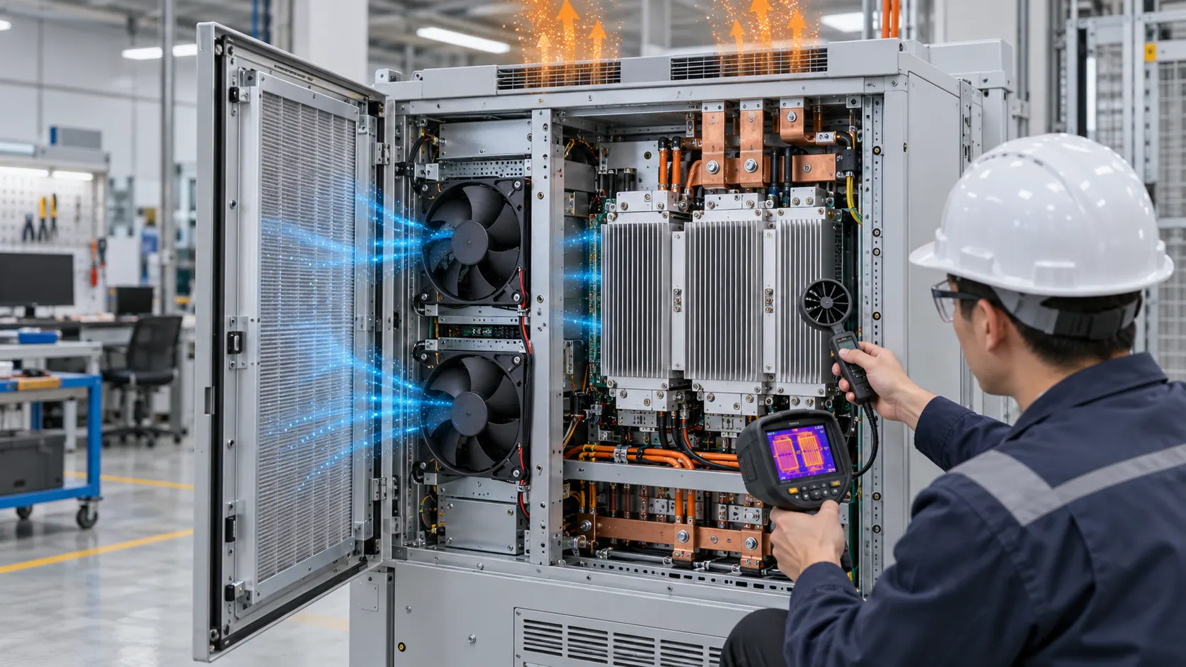
Liquid Cooling Still Has an Air-Side Heat-Rejection Problem
An anonymized North American BESS integrator needed to validate the fans behind a liquid-to-air dry cooler before releasing a high-ambient cabinet sample.
The battery modules transferred heat into a coolant loop, but the loop still had to reject that heat through a finned radiator exposed to outdoor air. The liquid side could be stable while the air side quietly lost capacity because of coil pressure drop, guard losses, fouling, recirculation or high entering-air temperature.
MEGA Tech reviewed the customer's cabinet sample, dry-cooler coil, fan opening, guards, control range, ambient conditions, voltage and noise limit. The task was not to select a fan from a free-air CFM number. It was to validate the installed air-side duty and show how fan control interacted with coolant supply and return temperature.
The customer identity and released acceptance values remain confidential. This case describes the engineering method and labels illustrative calculations rather than presenting them as customer test results.
The Engineering Hook: Liquid Cooling Does Not Remove Fan Selection
Cold plates and pumps control the coolant path; a dry cooler fan controls how effectively the final heat exchanger rejects heat to ambient.
The air-side working point is where the fan curve intersects the dry-cooler system curve. That curve includes the fin pack, guard, shroud, filter or screen, discharge restriction and any recirculation caused by the cabinet installation. A fan that looks adequate at free air may not deliver the required air mass flow across the coil.
The entering-air temperature matters as much as the fan command. A dry cooler cannot reject heat below the condition of the air entering its fins. At hot ambient, the controls may need more air, a higher coolant temperature, a larger coil, or a different operating envelope. The fan is one lever in the thermal system, not a substitute for coil area or pump flow.
COMSOL's BESS model describes the use of fan curves and pressure difference in an air-cooled cabinet. A liquid-cooled BESS changes the battery-side path, but the same operating-point logic still applies at the dry cooler. A 2025 SAE study also shows why fan speed, flow resistance and channel geometry should be evaluated together rather than independently.
The Problem in Operation: Coolant Temperature Was Stable but Airflow Margin Was Not
The first review found that the liquid loop hid changes on the air side until high ambient and dirty-coil conditions arrived together.
The integrator logged coolant supply and return temperature, coolant flow, entering and leaving air temperature, fan command, RPM or FG, current and differential pressure across the dry cooler. The test covered normal charge, high discharge, low-load circulation, hot afternoon ambient and a simulated fouling condition.
The team separated three questions: was enough heat arriving at the radiator, was enough air mass flow crossing the fins, and was the heat exchanger large enough for the entering-air condition? Raising RPM cannot repair an undersized coil or a blocked discharge. It can increase noise and auxiliary power while the coolant temperature remains above target.
The shroud and discharge were inspected for bypass. A portion of the fan flow that short-circuits around the coil contributes little to heat rejection but still appears in a simple fan-speed reading. The acceptance record therefore used temperature difference and air-side pressure together with fan feedback.
Interactive: Watch the Dry-Cooler Air Path Change With Fan Duty
The animated schematic shows the same coolant loop in three air-side states: useful coil flow, hot-ambient margin and a restricted coil.
The figure is qualitative, not CFD and not a product performance curve. It is a design-review aid: measure the complete air path, then compare fan duty with entering-air temperature, coolant temperatures, coil pressure and the thermal limit.
The sample sequence included clean and restricted coil conditions, low and high coolant flow, hot ambient, fan ramp-up, fan-fault response and restart. Each state recorded the actual fan voltage, current, control input and feedback so a future replacement or alternate supplier could be compared on the same basis.

Sample 01: Define Heat Rejection Before Choosing Airflow
The customer first converted battery and power-electronics heat into the dry-cooler duty instead of starting with a fan catalogue.
The required inputs were heat rejection over charge and discharge, coolant supply and return targets, maximum entering-air temperature, permitted coolant temperature rise, coil performance, air-side pressure loss, altitude, acoustic limit, available fan envelope and control range.
As an illustrative estimate, if the dry cooler must reject 18 kW at a 12 K coolant-side rise and the coolant has a heat capacity near 3.6 kJ/(kg K), the required coolant mass flow is approximately 18,000/(3,600 x 12) = 0.42 kg/s. That is a coolant-side estimate; it does not determine the air CFM. The air-side flow must come from the coil's heat-transfer data and entering-air condition.
For the air side, suppose a 5 kW sensible load is rejected with an air temperature rise of 8 K. Using Qv = P/(rho x cp x deltaT), the planning value is about 0.52 m3/s, or roughly 1,100 CFM at the assumed density. This is illustrative only; coil effectiveness, bypass, altitude and the manufacturer's performance data control the final value.
Sample 02: Match the Fan to Coil Pressure, Not Only Coil Face Area
A large radiator face can still require substantial pressure if the fin density, guard and shroud are restrictive.
MEGA Tech reviewed the coil pressure-drop curve at the target air density and flow. The candidate fan was compared at the installed shroud and guard, with the real inlet and discharge clearances. The sample was not accepted because it had the largest free-air number; it was accepted only if the operating point preserved the required heat-rejection margin.
The control sequence retained a minimum protective duty, a normal thermal band and a high-ambient response. Hysteresis prevented the fan from hunting around a temperature threshold. FG or RD feedback was included where the integrator needed confirmation of fan operation, but feedback was not treated as proof of radiator airflow.
Auxiliary power was recorded as part of the thermal balance. A 48 V fan drawing 1.2 A consumes about 57.6 W; two fans consume about 115 W before controller losses. These are illustrative values, not MEGA specifications. The project should compare fan power with the thermal reserve and the BESS auxiliary-energy budget.
The comparison also stated the air-density basis. At altitude or high entering-air temperature, volumetric flow and mass flow are not interchangeable. A supplier should state whether the P-Q curve is reported at standard density, and the integrator should use the density at the dry-cooler inlet when estimating heat rejection. This prevents a catalogue CFM value from being treated as a universal cooling capacity.
The shroud was checked for bypass with a smoke or tracer-flow observation and with temperature measurements across the face of the coil. If the center of the coil was active but the perimeter was short-circuiting, the next action was a layout or seal correction rather than an immediate RPM increase. This is especially important when several fans share one radiator: a local gap can consume air-side pressure while leaving parts of the fin pack underused.
Sample 03: Validate Hot Ambient, Fouling and Fan-Fault States
The dry cooler was tested in the conditions most likely to erode thermal margin after commissioning.
The team repeated the test at the hottest allowed entering-air condition and with a controlled increase in coil resistance. It recorded leaving-air temperature, coolant return temperature, surface temperature, pressure drop and fan current. This showed whether the control system had useful headroom or was already at maximum duty.
A single fan was disabled where the architecture allowed an N+1 review. The remaining fans were checked for reverse flow, recirculation and pressure interaction. A failed fan that becomes a restriction can reduce the useful flow of its neighbors; the system should be tested rather than assuming redundancy equals performance.
The customer also reviewed rain, dust, salt, service access, bearing life, vibration and noise at the boundary. MEGA Tech supplied fan-side data and sample support; the BESS integrator retained responsibility for coolant safety, leak detection, battery protection, fire controls and the complete system qualification.
Altitude was included in the review because lower air density changes the relationship between volumetric flow, mass flow, pressure and heat rejection. The same CFM at a high site does not carry the same mass of air as it does at sea level. The test record therefore stated the density basis and avoided comparing curves measured at different conditions without correction.
Noise was measured at the site boundary and near the dry-cooler inlet because the highest fan command is not always the loudest installation state. Grilles, coil turbulence and structural panels can add tonal content. A lower-noise fan that misses the coil duty is not an improvement, but a fan with pressure headroom can often be controlled below maximum speed during normal operation while retaining hot-ambient reserve.
Validation Result: The Fan Sample Made Air-Side Margin Visible
The transferable result was a dry-cooler validation method that linked coolant data, air data, fan feedback and auxiliary power.
The release record documented fan P-Q data, air density basis, coil and guard pressure, entering-air temperature, coolant supply and return conditions, fan command, current, feedback, noise, mounting and service assumptions. This made it possible to distinguish a fan limitation from a coil, pump, coolant or control limitation.
The result was not a universal claim that one fan size fits every liquid-cooled BESS. It showed the customer where to place sensors and how to compare a custom or replacement fan at the real air-side working point. Same voltage and outline dimensions are not enough when the coil, shroud, pressure path or hot-ambient condition changes.
The customer could then decide whether the next improvement belonged in the fan, the coil, the shroud, the control curve, the coolant loop or the cabinet layout. That is a more useful procurement decision than choosing a fan by maximum CFM.
For a production review, the pass/fail sheet should include at least one normal point, one hot-ambient point, one restricted-coil point and one fan-fault point. Each point should show coolant temperatures, entering and leaving air temperatures, differential pressure, fan command, current and the available thermal margin. The same sheet can then be used for incoming inspection and for a replacement-fan comparison.
How MEGA Tech Supports Liquid-Cooled BESS Fan Customization
MEGA Tech supplies fan-side engineering and samples for the dry-cooler boundary of a liquid-cooled BESS.
We can review high-ambient DC axial fans and compact centrifugal blowers, coil pressure drop, shroud and guard losses, airflow direction, PWM and FG/RD signals, connector and lead-wire details, bearing and life targets, IP and environmental requirements, voltage tolerance and small first-build quantities. We can also evaluate alternatives to Sanyo Denki, SUNON, Delta, NMB, ebm-papst and other installed brands when the operating point is defined.
Please provide heat rejection over the operating modes, coolant supply and return targets, maximum entering-air temperature, coil data, required air-side flow and static pressure, fan size, voltage, quantity, control, noise, altitude, environment and life assumption. If the data is incomplete, send the current fan model, coil drawing, cabinet photos and measured temperature or pressure points.
Our scope is fan and air-path engineering, sample customization and comparative validation. We do not supply the customer's cold plates, pump, coolant, chiller, BMS, cabinet safety design, emergency ventilation or battery protection system.
Engineer Questions About This Dry-Cooler Case
Use these questions before approving a fan for a liquid-cooled BESS heat-rejection unit.
Q: If the battery is liquid cooled, do I still need a high-static fan? A: Often the radiator, guard, shroud and outdoor restrictions create a meaningful air-side pressure duty. Use the coil curve and installed system curve to decide.
Q: Can fan RPM prove that the dry cooler is rejecting enough heat? A: No. Compare coolant temperatures, entering and leaving air, pressure, airflow or a defensible proxy, and fan feedback.
Q: What is the first hot-ambient check? A: Confirm entering-air temperature, coolant target, coil capacity and fan headroom together. A higher command cannot overcome a coil or temperature-limit mismatch.
Q: Should a failed fan be left open to the air path? A: Test the real module. The idle path can create reverse flow or extra resistance and change the neighboring fan operating points.
Q: What should I send for a fan review? A: Send heat rejection, coolant targets, entering-air range, coil pressure curve, airflow and static pressure, fan size, voltage, quantity, control, noise, environment and life target.
Q: Can MEGA Tech provide a custom sample? A: Yes. We can review the installed dry-cooler duty and support a sample comparison before production release.
Need a Dry-Cooler Fan Specification?
Send the heat-rejection duty, coil pressure drop, entering-air temperature, coolant targets, fan size, voltage, control interface and noise limit. MEGA Tech will review the installed air-side operating point before recommending a sample.
Include the current fan model, radiator or coil drawing, shroud and guard details, cabinet photos, altitude, service environment and any pressure, airflow, coolant or temperature data available. This helps separate a fan problem from a coil, pump, coolant, control or cabinet-layout problem before the production BOM is locked.