The Cabinet Was Cool Enough — Until Night Conditions Changed
An anonymized European BESS integrator needed to validate a cabinet fan sample for hot days, humid nights and repeated door or service events.
The battery cabinet did not have one simple thermal state. During charge and discharge, the cells and power electronics generated heat. After shutdown, the metal cabinet and battery mass cooled at a different rate from the incoming air. On humid mornings, a normal room-temperature reading did not prove that every busbar, panel, connector or cold surface remained above the local dew point.
MEGA Tech reviewed the customer's cabinet sample, filter, fan opening, heat sources, control sequence, humidity sensors, voltage, pressure path and service conditions. The goal was not to claim that a fan prevents condensation by itself. The goal was to find a fan and control envelope that supported the customer's humidity and dew-point strategy without creating unnecessary auxiliary power or moving humid air into a cold zone.
The customer identity and released acceptance values remain confidential. This case describes the engineering workflow and uses clearly labelled illustrative calculations where customer measurements cannot be disclosed.
The Engineering Hook: A Fan Can Move Heat and Moisture at the Same Time
Temperature control and condensation control are related, but they are not the same duty.
Condensation becomes possible when a local surface is colder than the dew point of the air touching it. A cabinet-average temperature or one RH sensor cannot prove that a cold corner, cable gland, metal bracket or heat-exchanger surface is safe. The measurement must be time-aligned and located near the suspected surface.
The practical design question is therefore more precise than 'how many CFM does the cabinet need?' It is: which air path removes the heat, what pressure drop does the filter and grille create, where does humid air enter, and which control state is allowed when the dew-point margin becomes small?
ASHRAE moisture-management guidance treats dew point and surface temperature as a system problem. An independent BESS condensation review likewise points to local surface conditions, door events, shutdown, drainage and airflow short-circuiting as causes that can be missed by a single average reading. The fan is one controllable part of that chain, not the complete humidity solution.
The Problem in Operation: Normal Temperature Did Not Prove a Safe Dew-Point Margin
The first field review showed why a cabinet can look thermally acceptable while still needing a better humidity-control test plan.
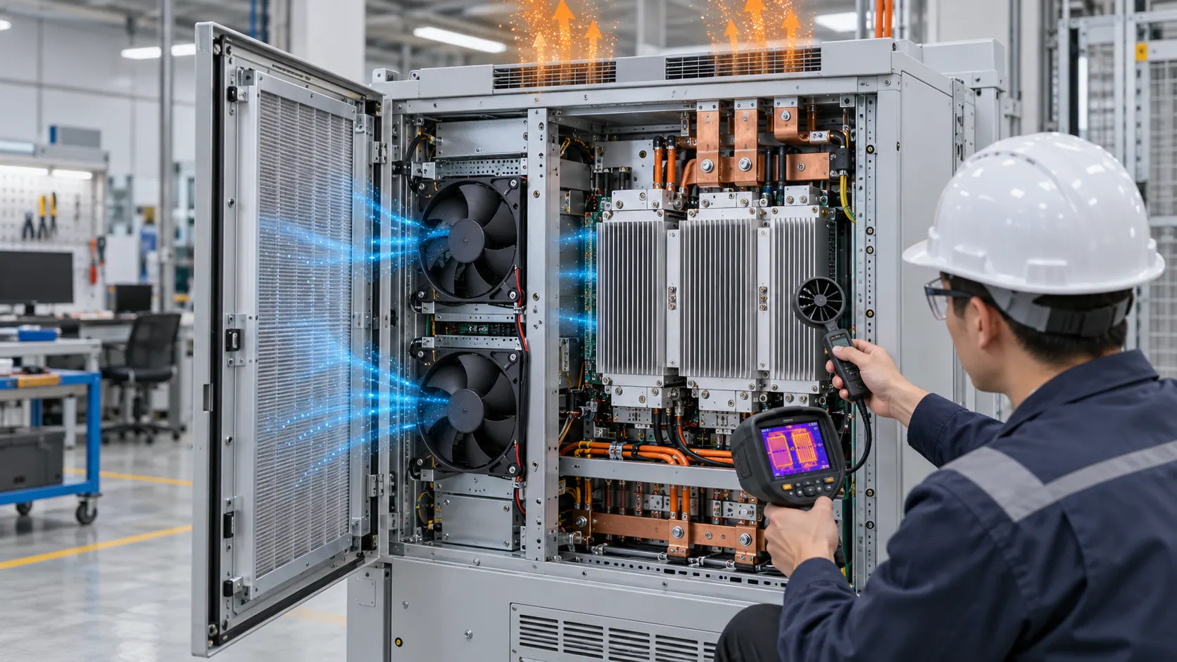
The integrator logged air temperature, relative humidity, calculated dew point and selected surface temperatures during charge, discharge, fan ramp-down, shutdown, overnight soak and morning restart. The event was not treated as a simple high-temperature alarm. The team recorded whether a door had opened, whether the filter had changed resistance, whether the HVAC or dehumidification stage was active, and whether the fan was exhausting or recirculating.
A useful acceptance record compares the coldest measured surface temperature with the local dew point and keeps a project-defined margin. The exact margin belongs to the cabinet designer and environmental qualification plan. It must not be invented from a catalogue fan rating. The log should also capture the time derivative: a surface that is still above dew point but falling quickly may need a different recovery action from a stable surface with the same instantaneous margin.
The air path was also inspected for bypass. A fan can show RPM feedback while most of its flow takes a low-resistance route around the rack or filter. That can increase fan power and noise without protecting the cold surface that matters. For a practical review, place one measurement point upstream of the filter, one after the filter and one near the farthest thermal load. Compare the readings with the fan command and pressure drop; do not infer the remote-zone airflow from RPM alone.
The team defined a pass/fail record before changing the fan: no unplanned surface wetting at the monitored locations, acceptable thermal margin at the limiting electronics, stable feedback through the command transitions, and a documented recovery time after a humid event. These criteria kept the fan comparison tied to the cabinet's risk rather than to an attractive but incomplete datasheet number.
Interactive: Watch Fan Duty Change Across Humidity States
The animated schematic separates a dry safe state, a humid recovery state and a cold-surface risk state so the control logic can be reviewed before a sample is frozen.
The figure is qualitative, not CFD and not a BESS safety-control specification. It shows why a fan command should be evaluated with humidity, dew point, surface temperature and cabinet state. A control system may need a minimum circulation state, a controlled recovery state, a dehumidification request or an interlock defined by the BESS designer.
The validation sequence used clean-filter and loaded-filter conditions, normal operation, reduced-power operation, shutdown, door opening, humid restart and sensor-fault handling. Each state recorded fan voltage, current, PWM, RPM or FG, pressure drop, air temperature, RH, calculated dew point and critical surface temperatures.

Sample 01: Freeze the Heat Load and Dew-Point Envelope
The fan sample was selected only after the customer defined both sensible heat removal and the environmental states that could create condensation.
The integrator supplied the cabinet envelope, rack arrangement, heat-source map, filter and grille, fan opening, ambient temperature range, humidity range, altitude, voltage tolerance, control interface and service assumptions. MEGA Tech then reviewed compact axial and blower options against the installed pressure path rather than free-air airflow.
As an illustrative heat-balance estimate, suppose the air-cooled electrical section rejects 240 W and the design allows a 10 K average air rise. Qv = P/(rho x cp x deltaT) gives approximately 0.020 m3/s, or about 42.4 CFM, before local hot spots, leakage and filter loading are considered. This is a planning estimate, not a guaranteed fan requirement. The final airflow must come from the actual system curve and measured temperatures.
For the humidity side, the team recorded dew point from temperature and RH at the relevant location and compared it with the coldest accessible surface. A single RH percentage was not used as a substitute for dew point. The test plan also marked the door, cable-entry and drain paths because moisture can enter through events that a fan cannot correct.
Sample 02: Separate Cooling Command From the Condensation Interlock
The control review prevented a common mistake: using fan RPM as the only answer to a dew-point problem.
The candidate fan supported a minimum circulation command, a normal thermal-control band and a higher-duty response when heat load increased. The humidity and dew-point strategy remained under the customer's BMS or HVAC control ownership. MEGA Tech documented the fan response, feedback, locked-rotor behavior and current so the integrator could use those signals in its own control logic.
A fan can reduce local temperature gradients, but it can also bring humid ambient air across a surface that is still cold. Whether to circulate, limit outside-air exchange, request dehumidification, warm a surface or delay restart must be decided from the complete cabinet design. The article's animated figure is intended to make that review visible, not to prescribe one universal sequence.
The auxiliary-power estimate was kept explicit. A 24 V fan drawing 0.40 A uses about 9.6 W; four such fans would use about 38.4 W before control losses. These are illustrative values only. The selected fan's actual current, duty cycle, start current and site auxiliary-power budget must control the final decision.
Sample 03: Validate Filter Loading, Night Restart and Sensor Placement
The most useful sample test reproduced the transitions that were most likely to expose a dew-point or airflow problem.
The filter was tested clean and loaded because its pressure drop changes the installed operating point. The team measured airflow or a defensible proxy at the cabinet, not only at the fan outlet. The fan sample was checked at the customer's voltage range and with the grille, guard, filter, cable routing and enclosure panels installed.
Night restart was treated as its own test. After the cabinet reached a cold soak, the team introduced the project-defined humid condition and recorded sensor response, fan ramp, surface temperature and recovery time. The result was not reduced to 'fan on' or 'fan off'; the sequence was compared with the customer's dew-point margin and equipment-protection logic.
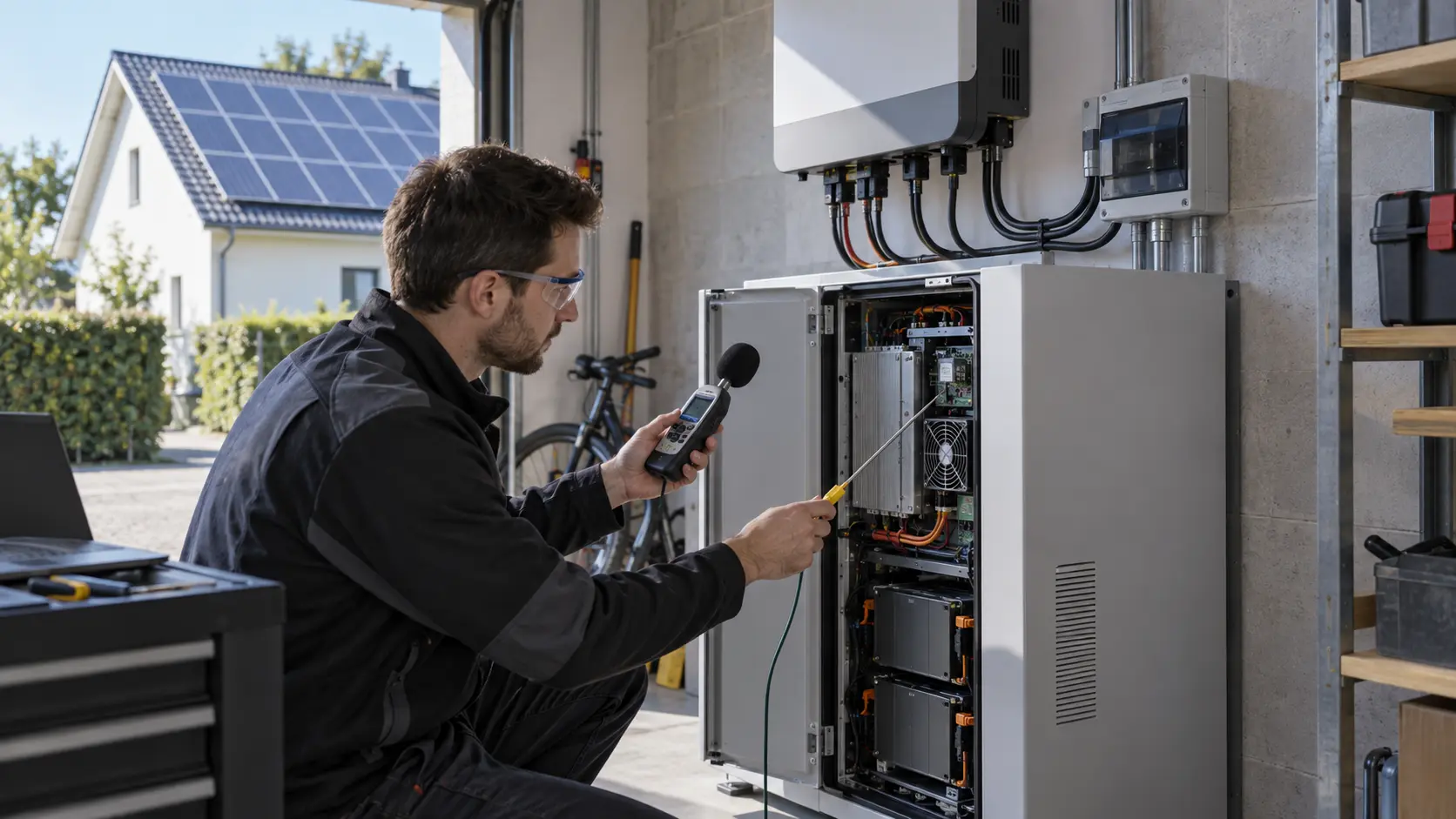
Sensor placement was reviewed at more than one height where stratification or local cold zones were plausible. A sensor close to the fan inlet can miss the condition at a remote busbar or lower cabinet corner. The BESS integrator remained responsible for sensor redundancy, alarms, fire-safety controls and final environmental qualification.
Validation Result: The Fan Sample Supported a Measurable Control Envelope
The result was not a universal humidity percentage or a promise that a fan alone prevents condensation; it was a repeatable validation method.
The selected sample gave the integrator a documented relationship between fan duty, installed pressure, filter condition, air temperature, relative humidity, dew point, surface temperature and auxiliary power. That made it possible to review normal operation and transition states using the same evidence instead of relying on an isolated RPM or CFM number.
The release package documented the fan P-Q curve, operating voltage, PWM/FG/RD behavior, current, pressure points, filter state, temperature rating, bearing or life assumption, connector, mounting and sample conditions. It also listed what the fan does not prove: cabinet sealing, dehumidifier capacity, drainage, fire-safety ventilation, BMS logic or battery safety compliance. This separation is useful for procurement because it tells the buyer which values belong in the fan specification and which values must remain in the cabinet or plant qualification file.
For procurement, the transferable lesson is important. A custom or replacement fan should be judged by the installed thermal and environmental duty. Same outline dimensions are not enough if the filter, pressure path, humidity sequence or control interface changes.
How MEGA Tech Supports BESS Fan Customization
MEGA Tech develops fan samples around the BESS cabinet's real pressure path, heat load, environmental condition and control interface.
We can review high-ambient DC axial fans and compact centrifugal blowers, filter pressure, grille open area, airflow direction, PWM and FG/RD signals, connector and lead-wire details, bearing and life targets, IP and environmental requirements, voltage tolerance and small first-build quantities. We can also evaluate alternatives to Sanyo Denki, SUNON, Delta, NMB, ebm-papst and other installed brands when the operating point is defined.
Please provide the cabinet heat load, airflow and static-pressure target at that airflow, temperature and altitude basis, voltage tolerance, fan size, quantity, control interface, connector, noise target, filter condition, humidity/dew-point range, critical surface temperatures and life assumption. If data is incomplete, send the current fan part number, cabinet photos and any measured temperature, pressure or humidity points.
Our scope is fan and air-path engineering, sample customization and comparative validation. We do not supply the customer's BMS, liquid loop, HVAC, cabinet safety design, emergency ventilation or battery protection system. Those boundaries should remain explicit in the procurement and qualification documents.
Engineer Questions About This BESS Condensation Case
Use these questions before approving a cabinet fan or humidity-control sequence.
Q: Can a higher-CFM fan solve condensation? A: Not by itself. Condensation depends on local dew point and surface temperature; airflow must be evaluated with sealing, dehumidification, drainage and control logic.
Q: Is relative humidity enough for a fan specification? A: No. Record temperature, RH and calculated dew point at the relevant location, then compare it with critical surface temperatures and the project-defined margin.
Q: Should the fan run continuously at night? A: That is a system decision. Test the fan, cabinet, HVAC or dehumidification strategy and cold surfaces during shutdown and restart before selecting the sequence.
Q: What happens when the filter loads? A: Pressure drop rises and the fan operating point moves. Test clean and loaded conditions, and record the maintenance limit instead of assuming RPM proves airflow.
Q: What should I send for a BESS fan review? A: Send heat load, airflow and static pressure, fan size, voltage, quantity, control, filter, noise, humidity/dew-point range, critical surface temperatures, environment and life target.
Q: Can MEGA Tech provide a custom sample? A: Yes. We can review the installed duty, adjust the fan and control requirements, and support a sample comparison in the customer's cabinet before production release.
Need a Dew-Point-Aware Fan Specification?
Send the BESS heat load, airflow and static-pressure target, fan size, voltage, control interface, humidity range and critical surface temperatures. MEGA Tech will review the installed operating point before recommending a sample.
Start with the product information page, or contact a MEGA Tech engineer directly. Include the current fan model, cabinet photos, filter and grille details, sensor locations, night or service sequence and any temperature, pressure, humidity or dew-point data available. This helps separate a fan problem from a moisture-entry, surface-temperature, control or drainage problem before the production BOM is locked.