The Fans Passed the Bench Test, but the Rack Failed Commissioning
An anonymized AI-infrastructure integrator had enough fan capacity on paper, yet several rack positions showed uneven inlet temperature during site acceptance.
The cooling units were operating, the server fans reported normal speed and the room average looked acceptable. The problem appeared only when the rack was loaded: some cold-aisle air bypassed the equipment while warm exhaust returned around the top and cable openings.
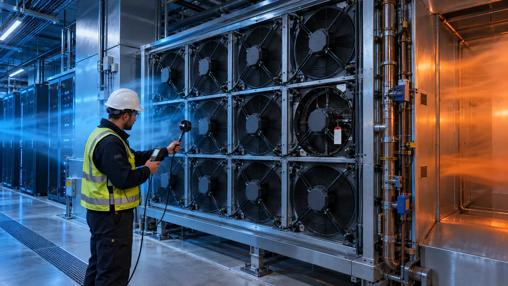
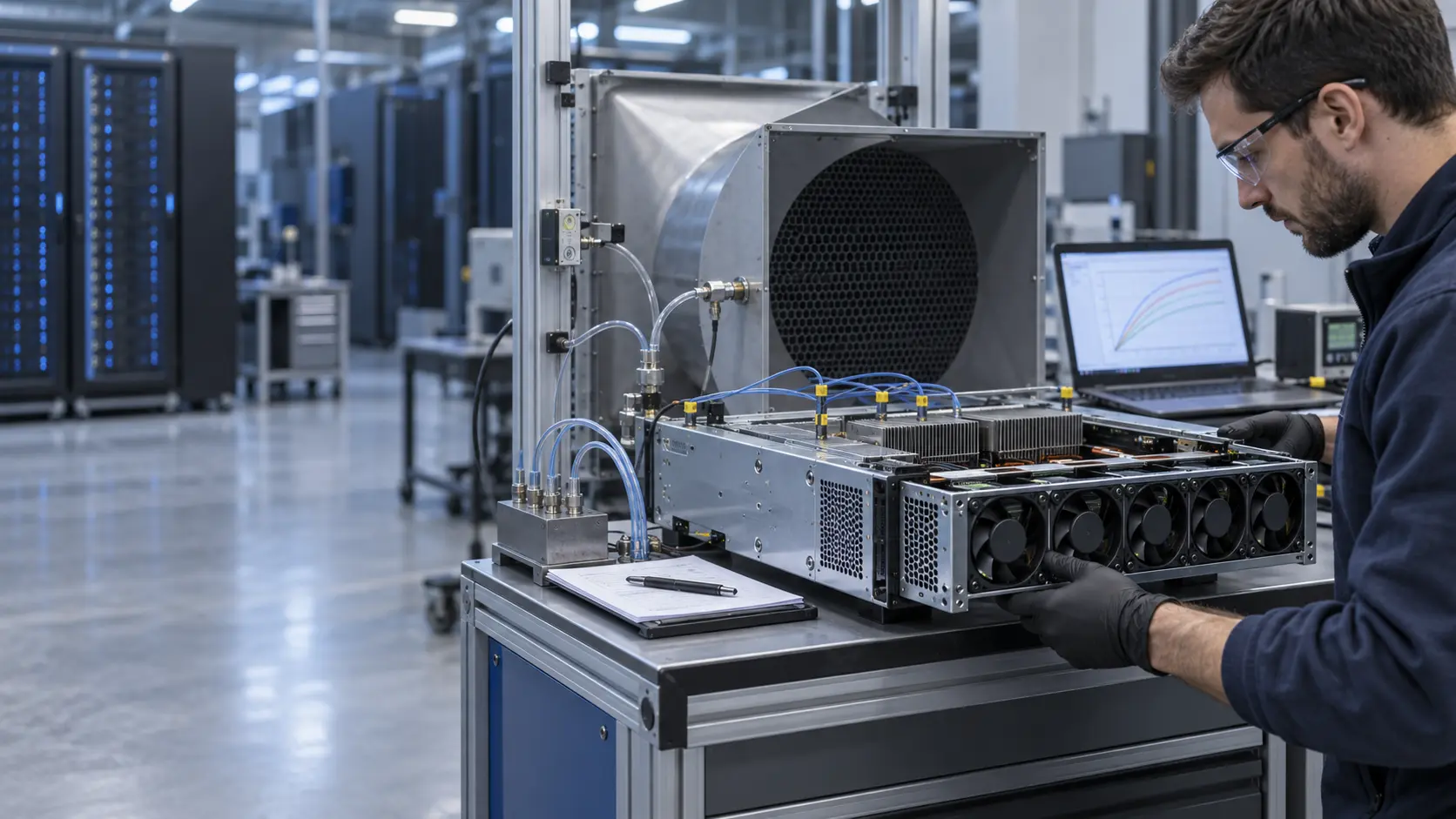
MEGA Tech reviewed the fan tray, rack openings, blanking panels, supply distribution, return path, inlet measurement points and installed pressure. The goal was to separate a fan-capacity problem from a room-air-management problem before changing the fan specification.
The customer identity and released acceptance values remain confidential. Values marked illustrative are engineering examples, not customer test results.
The Engineering Hook: Cooling Capacity Is Not the Same as Useful Rack Airflow
A cooling unit can deliver air to the room while the server inlet receives too little or too warm air.
ASHRAE and DOE guidance both emphasize hot-aisle/cold-aisle separation, blanking panels, sealed cable paths and measurement at the equipment inlet. Those controls reduce bypass and recirculation, allowing the cooling system to match airflow to actual heat load instead of compensating for leakage.
For a fan supplier, this matters because the fan P-Q point is set by the installed path. If the rack has an open slot or a leaking cable brush, the fan may move air through the wrong route. Raising RPM can hide the symptom temporarily while increasing power and noise.
The commissioning question is therefore: what airflow and inlet condition reach the limiting server at the stated rack load and pressure? Only after that question is answered can a custom fan sample be compared fairly.
The Problem in Operation: One Room Average Hid Three Rack Conditions
The integrator initially used one room sensor and one supply-air value, but the rack inlet changed with height and containment condition.
The team logged supply air, return air, rack inlet temperature at three heights, exhaust temperature, fan command, rack power, floor or grille pressure and the condition of blanking panels and cable openings. Tests were repeated at stable load and during a power step.
The lower inlet was close to the intended supply path. The upper inlet was influenced by warm-air recirculation, while an unused rack opening created a bypass path that reduced useful flow through neighboring equipment. The room average could not show either effect.
The acceptance record therefore named the measurement plane, probe position, rack load, containment state and stabilization time. Without those details, two teams can report different ‘rack airflow’ values while both measurements are technically correct at their own locations.
Interactive: Watch Bypass and Recirculation Compete
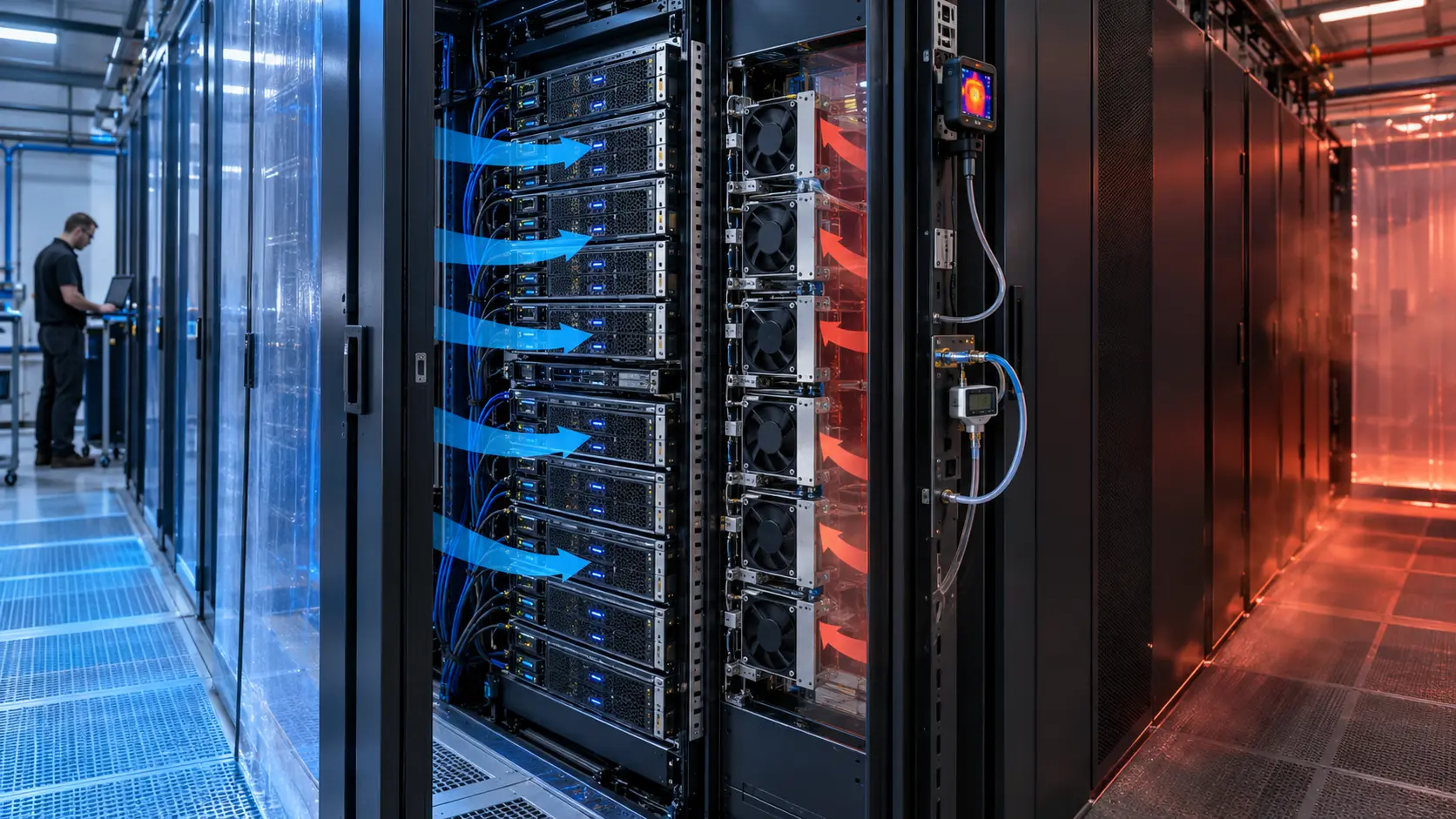
The animated schematic shows blue supply air bypassing the load while amber exhaust returns toward the upper inlet.
The figure is qualitative, not CFD and not a facility performance result. It explains why sealing an opening or changing the fan duty can move the operating point. A higher fan command does not automatically improve the hottest inlet if the additional air follows a bypass route.
The test sequence compared the rack with normal panels, a controlled opening, and corrected sealing. Each state retained the same load and recorded inlet temperature, pressure, fan command and exhaust condition so the effect of the air path was visible.

Sample 01: Map the Installed Air Path Before Selecting a Fan
The first sample task was a physical map of every inlet, outlet, opening and obstruction around the rack.
The integrator documented server airflow direction, fan-tray opening, heat sinks, rack rails, cable brushes, blanking panels, floor tiles, containment, neighboring racks and return-air path. A smoke or particle visualization was used only to locate the path; acceptance still relied on measured temperature, pressure and airflow.
For an illustrative heat-balance estimate, a 10 kW rack with a 12 K air rise requires about 0.69 m3/s, or roughly 1,460 CFM at an assumed density of 1.18 kg/m3. This is a rack-level planning value. It does not tell the engineer how many CFM each fan must deliver until the tray and rack resistance are known.
MEGA Tech used the map to identify whether the proposed fan needed more pressure, a different airflow direction, a seal change or a tray adjustment. The answer was not assumed from the maximum CFM label.
Sample 02: Measure Lower, Middle and Upper Inlet Duty
The second sample step made the rack inlet a measurable acceptance surface.
Temperature probes were positioned at lower, middle and upper inlet locations and correlated with the server telemetry where available. The team also measured differential pressure across the rack or tray and recorded the fan command and feedback at the same time.
A simple screening rule can be useful: if the upper inlet is 5 K warmer than the lower inlet at the same rack load, increasing all fans should not be the first response. Check recirculation, cable openings, blanking panels, supply balance and return path first. The 5 K value is an example trigger, not a universal limit.
Once the path was corrected, the candidate fan was compared at the same inlet plane and pressure condition. This prevented the fan sample from being blamed for a room-distribution problem or from masking one with excess speed.
Sample 03: Commission Normal, Step and Fault States
The final validation used the transitions that can expose an airflow mistake after handover.
The rack was tested at stable idle or inference load, a sustained high load and a controlled power step. A representative fan reduction or fault state was also checked where the architecture allowed it. Each state recorded inlet temperature, rack power, fan PWM, FG/RD status, pressure, acoustic condition and recovery time.
The purpose was not to claim a universal N+1 factor. It was to prove that the air path and fan control still protected the limiting inlet when the operating condition changed. If the rack only passes with every fan at maximum, the design has little margin for contamination, aging or a hot ambient condition.
The customer retained responsibility for facility cooling, containment, BMS/DCIM and server firmware. MEGA Tech supplied the fan-side operating data and helped define the installed sample comparison.
Validation Result: The Acceptance Test Found the Real Constraint
The final result showed whether the next engineering action belonged to the fan, the rack air path or the facility controls.
The release record included rack load, supply and return condition, inlet measurement positions, pressure, airflow method, fan P-Q data, PWM/FG/RD response, containment state, blanking-panel condition, noise and fault recovery. It also separated illustrative estimates from customer acceptance values.
The transferable lesson is that a fan cannot compensate indefinitely for bypass and recirculation. A custom fan may be the right answer when the installed pressure is too high or the tray needs a different duty, but the system must first ensure that useful air reaches the equipment.
For procurement, the correct comparison is not ‘which fan has the largest free-air CFM?’ It is ‘which candidate delivers the required airflow at the installed pressure while meeting control, noise, life and maintenance limits?’
How MEGA Tech Supports AI Rack Airflow Commissioning
MEGA Tech helps server and rack integrators connect fan selection with the installed air path and commissioning record.
We can review compact DC axial fans and blowers, tray pressure, grille and cable losses, PWM and FG/RD signals, connector details, vibration, acoustic limits, bearing and life targets, and small first-build quantities. We can also evaluate alternatives to Sanyo Denki, SUNON, Delta, NMB, ebm-papst and other installed brands when the operating point is defined.
Please provide rack or chassis heat load, airflow and static pressure at that airflow, temperature and altitude basis, fan size, voltage tolerance, quantity, control interface, connector, noise target, inlet measurement positions, containment condition, environment and life assumption. If data is incomplete, send the current fan part number, tray photos, rack layout and measured inlet or pressure points.
Our scope is fan and air-path engineering, sample customization and comparative validation. We do not supply the customer's server firmware, DCIM/BMS, CRAH/CRAC, containment or facility safety design.
Engineer Questions About This Commissioning Case
Use these questions before approving a rack fan, containment change or site-acceptance result.
Q: Is room temperature enough to accept rack cooling? A: No. Measure the air entering the limiting equipment at defined rack positions and loads.
Q: Why can more fan RPM fail to solve a hot upper inlet? A: The extra air may bypass the rack or strengthen a wrong recirculation path. Check the air path first.
Q: Do blanking panels really affect a fan selection? A: Yes. They change the system resistance and reduce mixing, so the installed fan operating point can move.
Q: How much airflow does a 10 kW rack need? A: It depends on the allowed air rise and density. For example, 10 kW and 12 K is about 0.69 m3/s at an assumed 1.18 kg/m3 density.
Q: What should I send for a review? A: Send heat load, airflow and pressure, fan size, voltage, quantity, control, noise, inlet positions, containment, environment and life target.
Q: Can MEGA Tech provide a custom sample? A: Yes. We can review the installed duty and support a sample comparison before production release.
Need an AI Rack Airflow and Fan Review?
Send the rack heat load, installed airflow and static pressure, fan size, voltage, control interface, inlet measurement positions, noise target and containment constraints. MEGA Tech will review the operating point before recommending a sample.
Include the current fan model, fan-tray photos, rack layout, workload profile, inlet-temperature data, containment condition and any pressure or acoustic measurements available. This helps separate a fan problem from a bypass, recirculation, sensor or facility-airflow problem before the production BOM is locked.