The Rack Was Below the Room Average but Still Throttled
An anonymized AI-infrastructure integrator found that one room-level temperature value was not enough to control a dense GPU rack.
The rack passed a room-level check, but a top-inlet zone saw warmer air during a sustained inference run. The server fans responded to their own inlet and component sensors, increasing speed and noise before the facility control loop recognised the local condition.
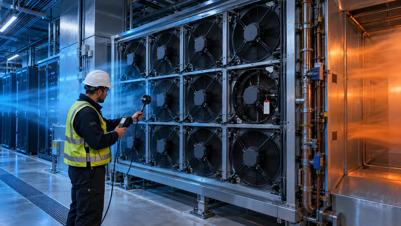
MEGA Tech reviewed the rack layout, containment, server fan trays, sensor locations, pressure path, control signals and thermal operating points. The objective was not to add a random room fan. It was to understand how sensor position changed the fan duty required to protect the limiting server and how an alternative fan sample should be validated in the installed rack.
The customer identity and released acceptance values remain confidential. Illustrative calculations are marked as examples, not customer results.
The Engineering Hook: The Sensor Controls the Fan You End Up Hearing
A sensor in the wrong air stream can make the system either overcool or react too late to a local recirculation path.
ASHRAE's AI data-center guidance recommends granular rack-inlet monitoring rather than relying only on room-level sensors. It also recommends hot- and cold-aisle management, containment and fan-speed control matched to actual IT load. A rack inlet sensor must therefore be placed where it sees the air entering the equipment, not in a convenient but bypassed part of the aisle.
A research study on server overheating detection similarly shows that simple sensor placement can underestimate the maximum component temperature. The precise sensor arrangement depends on the rack and server geometry, but the design principle is portable: locate and validate sensors against the thermal event you need to detect.
For MEGA Tech, this changes fan selection. The required P-Q point, PWM curve, FG/RD feedback and acoustic target should be reviewed against the actual inlet condition and control loop, not against a room setpoint alone.
The Problem in Operation: Room Temperature Hid a Vertical Gradient
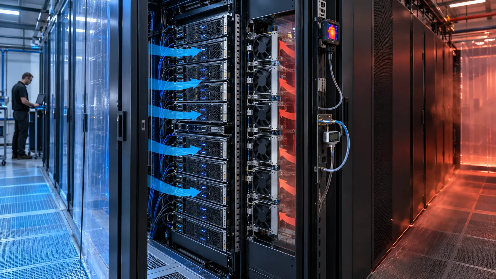
The rack was not uniformly exposed to the same inlet air because containment, cable openings and nearby return paths changed with height.
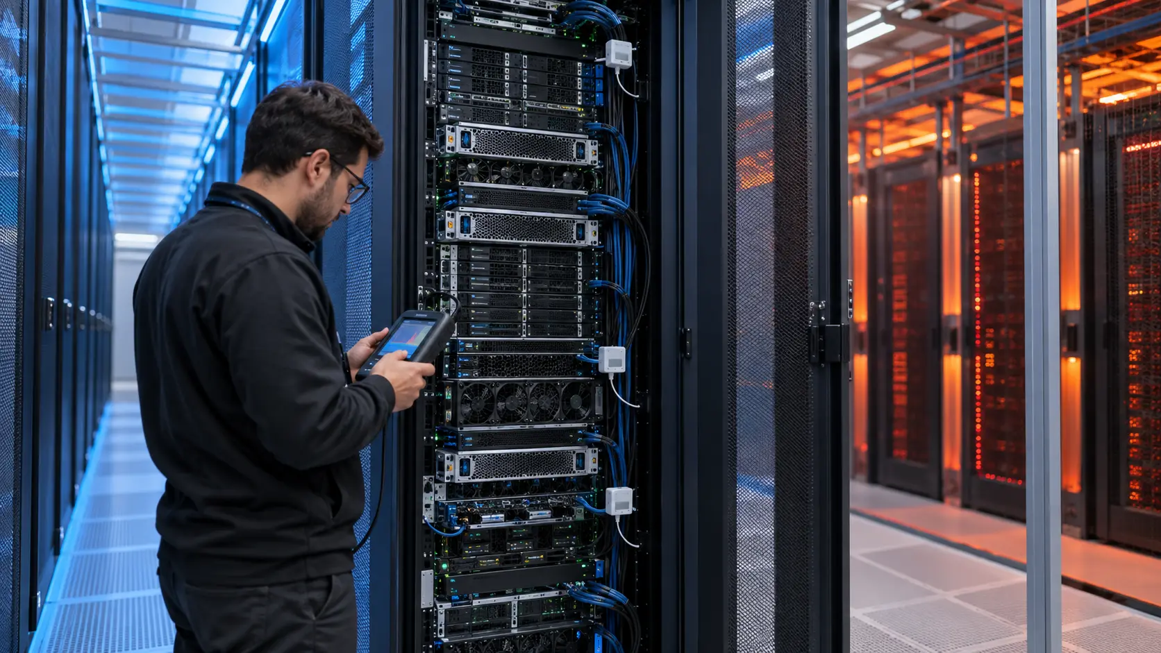
The integrator logged lower, middle and upper rack inlet temperature, server inlet telemetry, fan command, RPM or tach feedback, rack power, room supply condition and hot-aisle return temperature. The same workload was repeated at steady load and during a power step.
The upper sensor was closest to a recirculation path, while the lower sensor was influenced by supply air distribution. A room sensor between racks showed a comfortable average but could not prove the air at the top server inlet. The acceptance record therefore used the limiting inlet point and stated the sensor position explicitly.
The team also checked whether a fan-tray replacement changed the pressure balance. A fan that reaches the same RPM can deliver different airflow after a grille, blanking panel, cable brush or containment change. Temperature data and installed pressure were reviewed together.
Interactive: Watch Sensor Position Change Fan Demand
The animated schematic compares a room sensor, a representative rack-inlet sensor and a local hot-recirculation event.
The figure is qualitative, not CFD and not a server qualification result. It shows why the control input must be correlated with the hottest useful inlet point. A room sensor can remain stable while one rack inlet rises; a local sensor can react sooner but may overreact if it is placed in a bypass stream.
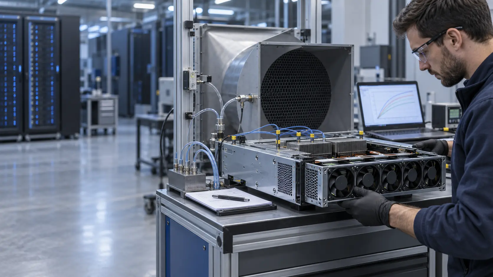
The validation sequence used normal load, a step increase, partial containment opening, one fan-tray fault and a recovery period. Each state recorded inlet temperatures, fan command, feedback, current, pressure and the limiting component temperature where available.

Sample 01: Map the Rack Before Selecting the Fan
The integrator first identified the air that each server fan tray actually received.
Inputs included rack power, server chassis, fan-tray opening, inlet and exhaust direction, containment, blanking panels, cable openings, aisle supply, return path, allowable inlet temperature, acoustic limit and control interface. The measurement plan placed sensors at the lower, middle and upper inlet positions and documented their distance from the chassis.
As an illustrative heat-balance estimate, a 12 kW rack load with a 12 K air rise requires about 0.83 m3/s, or roughly 1,760 CFM at the assumed density. That is a rack-level planning value, not a fan-tray specification. The installed pressure path and the server's internal airflow determine how the required flow is shared.
The team avoided using maximum CFM as the selection value. It asked where the candidate fan would operate after the server grille, filter, tray structure and rack pressure were included.
Sample 02: Tune the Control Loop Around the Limiting Inlet
The fan sample was compared at equal useful thermal duty, not simply equal PWM or RPM.
The candidate fan was checked for PWM response, FG or RD behavior, start current, minimum stable speed and operating-point pressure. The control curve used a normal band, a hot-inlet response and a fault state with defined hysteresis. This prevented rapid speed hunting around a sensor threshold.
A simple power estimate was recorded. A 12 V fan drawing 2.0 A uses 24 W; eight such fans use about 192 W before controller losses. These are illustrative values only. The actual server fan tray and facility power budget must control the specification.
The team also checked that the sensor input did not command unnecessary maximum speed when the inlet was cool but a remote component was hot for another reason. Sensor filtering, validation and alarm ownership remained part of the integrator's server and DCIM design.
Sample 03: Validate Recirculation, Fan Fault and Recovery
A fan replacement or control change was accepted only after the rack survived the transitions that matter in service.
The rack was tested with containment closed, a representative panel or cable opening, and a controlled return-air condition. One fan path was restricted or disabled where the architecture allowed it. The remaining fans were checked for reverse flow, pressure interaction and acoustic change.
The power-step test was important. During a rapid GPU load increase, the inlet sensor, server fan command and facility airflow loop responded at different speeds. The log showed the delay between the event and the hottest inlet, allowing the integrator to set a realistic alarm and recovery threshold rather than copying a room-level limit.
MEGA Tech supplied fan-side sample data and operating behavior. The data-center owner remained responsible for server firmware, DCIM/BMS logic, containment, facility cooling and IT equipment qualification.
Validation Result: The Limiting Inlet Became the Control Reference
The final sample gave the integrator a documented relationship between sensor position, fan duty, pressure, noise and rack thermal margin.
The release package documented the sensor locations, workload, rack power, inlet and exhaust temperatures, fan P-Q curve, PWM/FG/RD behavior, current, acoustic position, containment state, fault response and sample conditions. This made it possible to compare a replacement fan without hiding a rack-layout change inside the result.
The transferable lesson is not to place a sensor at the most convenient point or to control every fan from one average room value. Use a representative inlet reference, confirm it against the hottest useful position and keep enough thermal margin for power steps and fan faults.
For procurement, same frame size and voltage are not enough. The candidate must preserve useful airflow and pressure at the installed duty while meeting noise, feedback, life and control requirements.
How MEGA Tech Supports AI Server Fan Customization
MEGA Tech develops custom DC fan samples around the server tray, rack pressure, sensor strategy and operating point.
We can review compact axial fans and blowers, server fan-tray pressure, grille and filter losses, PWM and FG/RD signals, connector and lead-wire details, bearing and life targets, vibration, acoustic limits, voltage tolerance and small first-build quantities. We can also evaluate alternatives to Sanyo Denki, SUNON, Delta, NMB, ebm-papst and other installed brands when the operating point is defined.
Please provide rack or chassis heat load, airflow and static pressure at that airflow, temperature and altitude basis, fan size, voltage, quantity, control interface, connector, noise target, sensor positions, environment and life assumption. If data is incomplete, send the current fan part number, tray photos, rack layout and measured inlet or pressure points.
Our scope is fan and air-path engineering, sample customization and comparative validation. We do not supply the customer's server firmware, DCIM/BMS, CRAH/CRAC, containment or facility safety design.
Engineer Questions About This AI Rack Case
Use these questions before approving a fan tray, sensor point or control curve.
Q: Is a room sensor enough to control server fans? A: It can miss rack-level gradients and recirculation. Validate sensor position against the hottest useful inlet point.
Q: Does higher RPM prove better rack cooling? A: No. Compare installed airflow, pressure, inlet temperature and limiting component temperature.
Q: Why use sensors at multiple rack heights? A: Supply distribution, cable openings and hot-air recirculation can create vertical gradients that a single sensor misses.
Q: Should a fan fault immediately command all remaining fans to maximum? A: Test the pressure, thermal and acoustic response first; the correct response depends on the tray and rack architecture.
Q: What should I send for a fan review? A: Send heat load, airflow and pressure, fan size, voltage, quantity, control, noise, sensor positions, environment and life target.
Q: Can MEGA Tech provide a custom sample? A: Yes. We can review the installed duty and support a sample comparison before production release.
Need an AI Server Fan and Sensor Review?
Send the rack heat load, installed airflow and static pressure, fan size, voltage, control interface, sensor positions, noise target and containment constraints. MEGA Tech will review the operating point before recommending a sample.
Include the current fan model, fan-tray photos, rack layout, workload profile, inlet-temperature data and any pressure or acoustic measurements available. This helps separate a fan problem from a containment, sensor, control or facility-airflow problem before the production BOM is locked.