The Fan Was Healthy, but the Loaded Filter Moved the Operating Point
An anonymized AI-infrastructure integrator saw rising server fan duty and lower airflow after a rack filter accumulated dust, even though the fan alarm remained clear.
The first assumption was that the fan needed a stronger motor. The measured evidence suggested a different question: how much of the available pressure margin had the filter consumed, and at what point did the rack stop receiving useful airflow?
MEGA Tech reviewed the fan P-Q curve, filter pressure drop, grille and tray resistance, inlet temperature, fan command, current and maintenance plan. The objective was to define a loaded-filter validation method and determine whether the customer needed a different fan sample, a larger filter area, or a pressure-based service trigger.
The customer identity and released acceptance values remain confidential. Values marked illustrative are engineering examples, not customer test results.
The Engineering Hook: Filter Efficiency and Fan Pressure Are a Trade-Off
A filter protects equipment, but its resistance increases as it loads; the fan must still deliver the required airflow at the dirty condition selected for the design.
ASHRAE describes filter resistance, airflow velocity, filter loading and pressure indication as application variables. DOE guidance likewise notes that dirty filters increase static pressure and reduce airflow, and recommends using measured pressure drop as a maintenance input rather than relying only on a calendar.
For the server fan, the filter is part of system resistance. As pressure rises, the operating point moves along the fan P-Q curve. RPM can increase while useful airflow still falls, and the controller may create more noise and power without restoring the original thermal margin.
The right design does not simply select the highest-pressure fan. It balances particle protection, filter area, pressure drop, fan efficiency, noise, bearing life and the service interval that the operator can actually maintain.
The Problem in Operation: RPM Rose While Useful Airflow Fell
The rack controller reacted to warmer inlet air by increasing fan duty, but the loaded filter consumed much of the additional pressure margin.
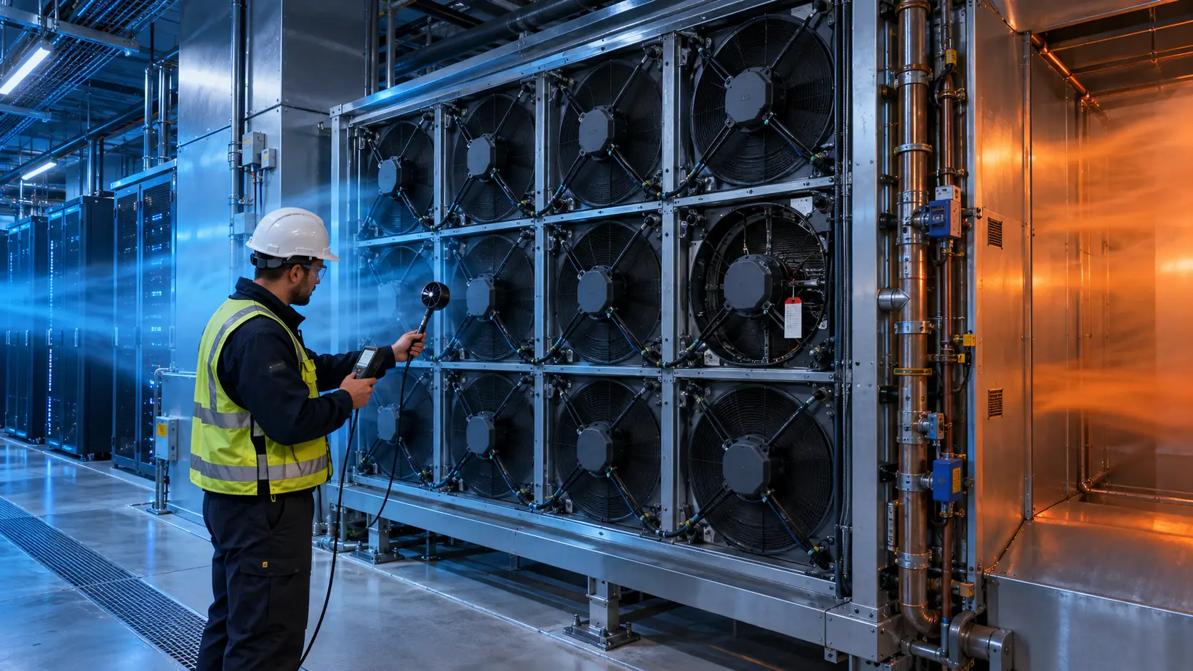
The integrator logged filter differential pressure, tray pressure, fan PWM, FG or RPM, current, rack power, inlet temperature at three heights and exhaust temperature. The same compute workload was repeated with a clean filter, a controlled loaded filter and the proposed service-limit condition.
The loaded state produced a higher command and a louder acoustic signature. Because the fan was near the left side of its installed P-Q curve, the extra RPM did not recover the same airflow ratio that it delivered with the clean filter. A room-level average did not reveal the local rack change.
The team therefore separated three decisions: whether the filter should be replaced, whether the fan has enough pressure margin, and whether the rack air path has an additional restriction. These are related but not interchangeable.
Interactive: Watch Filter Loading Move the Duty Point
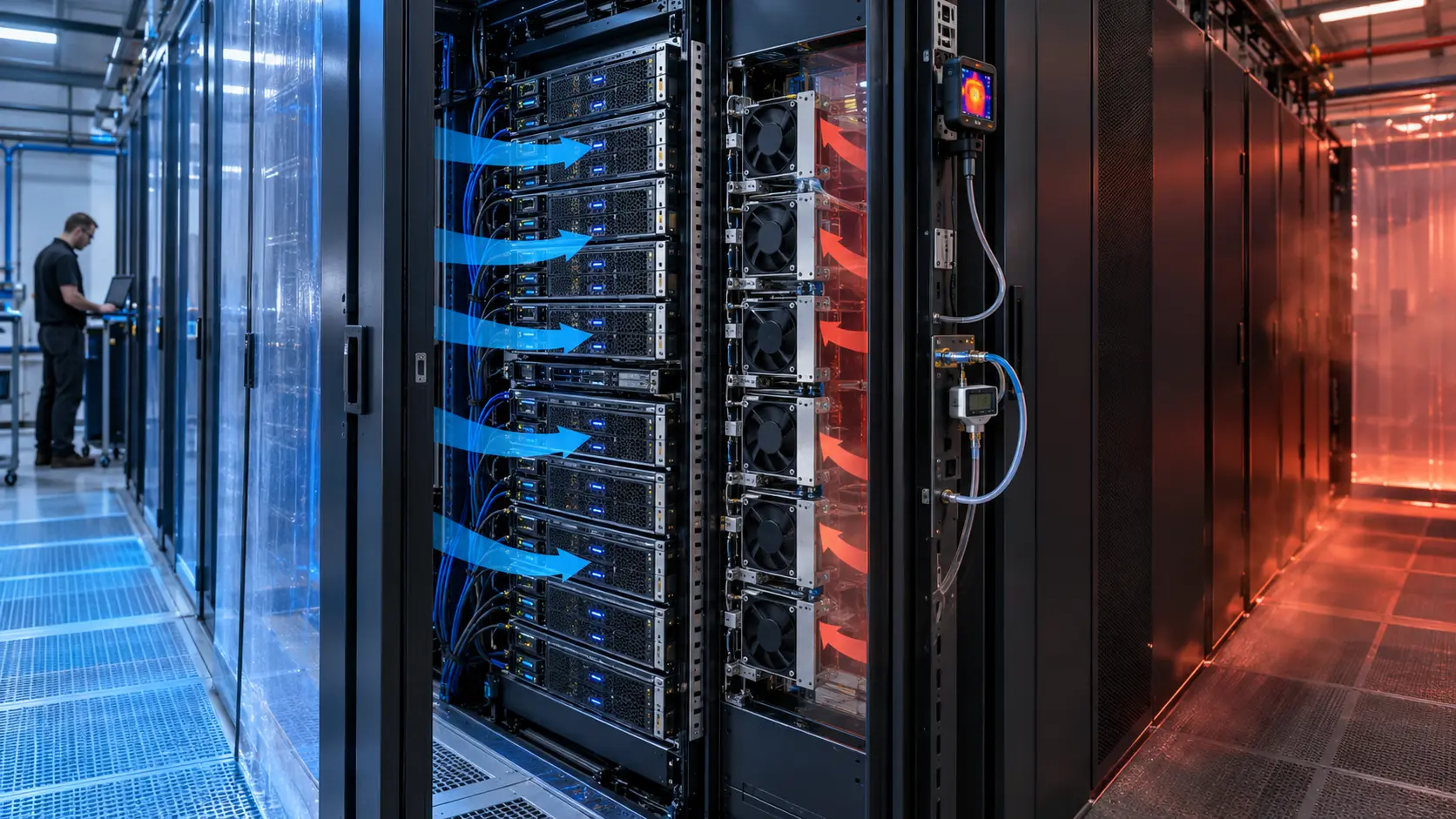
The animated schematic compares a clean path with a loaded path and shows the pressure margin being consumed.
The figure is qualitative, not a universal pressure multiplier or product curve. It shows why a filter cannot be treated as a constant accessory. The fan, filter, grille, heat sink and rack opening form one system resistance.
The test retained the filter area, mounting seal, fan command, voltage, workload and sensor positions. This made it possible to compare a candidate fan without confusing filter bypass or leakage with fan performance.

Sample 01: Define Clean, Loaded and Service-Limit Conditions
The first sample task was to define filter states that could be reproduced by the customer and supplier.
The integrator recorded filter media, face area, rated airflow, initial pressure drop, loading method, sealing condition and the final pressure-drop criterion. A visual label such as ‘dirty’ was not enough because dust distribution and bypass can make two filters with the same appearance behave differently.
For an illustrative pressure budget, if the clean filter contributes 40 Pa, the rack and tray contribute 120 Pa and the loaded filter contributes 160 Pa, total resistance rises from 160 Pa to 280 Pa. The 75% increase is a planning example; the actual values must be measured on the customer's assembly.
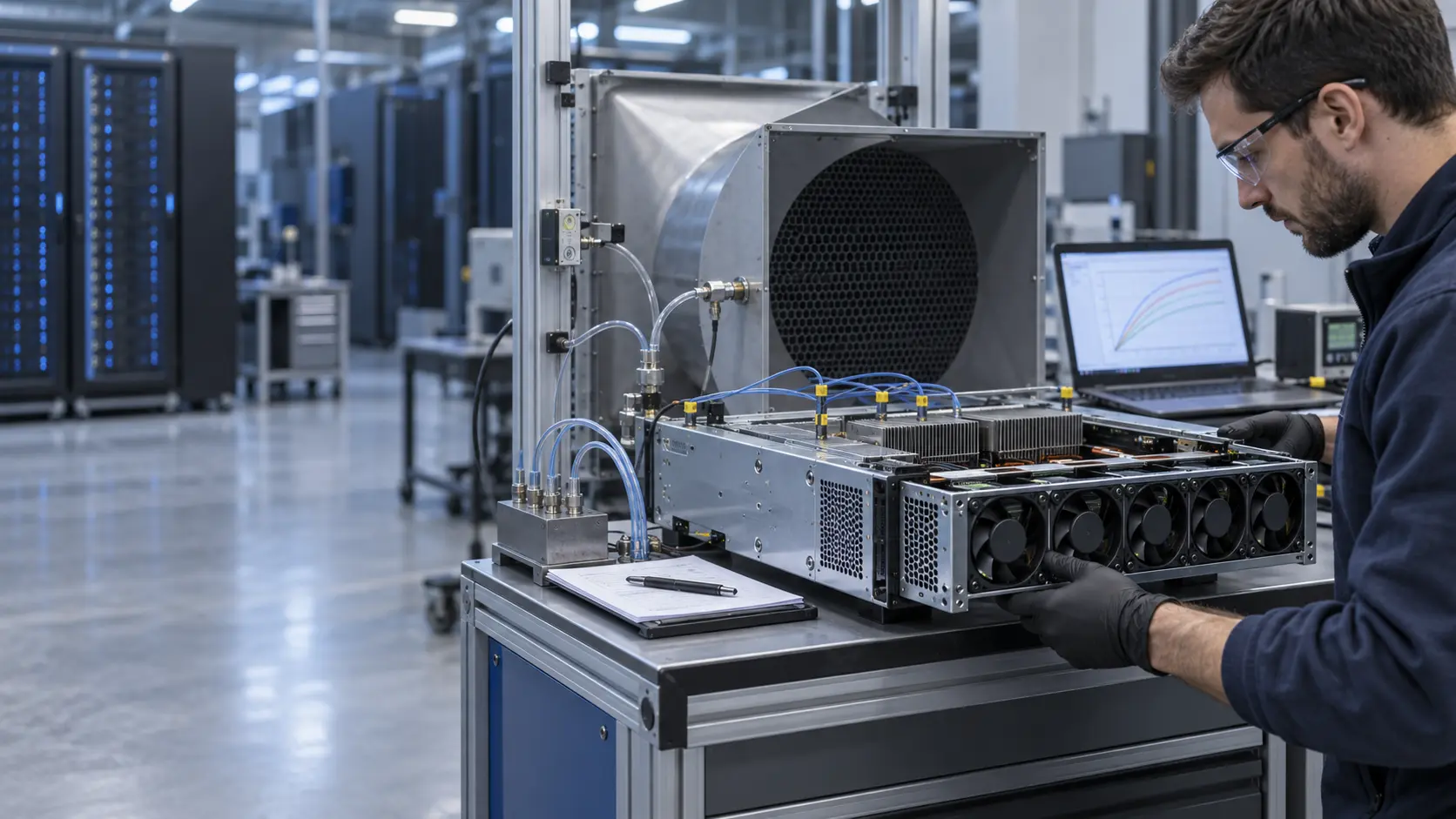
MEGA Tech used the defined states to check whether the custom fan sample maintained the required airflow at the loaded condition without exceeding current, noise or temperature limits.
Sample 02: Compare Pressure, Airflow and Thermal Margin
The second sample was tested at the actual filter and rack restriction instead of at a clean free-air condition.
A simple heat-balance example helps size the measurement. If a 12 kW rack allows a 12 K air rise, the required flow is about Q = 12,000 /(1.18 × 1,005 × 12) = 0.85 m3/s, or approximately 1,800 CFM at the assumed density and specific heat. This is a rack-level estimate, not a fan specification.
The acceptance record then checked the candidate fan at the clean and loaded pressure points. If airflow at the loaded state falls below the thermal requirement, the next action may be a higher-pressure fan, a larger filter area, a lower-resistance media, a different tray seal or a revised maintenance trigger.
The fan was not accepted because it held RPM. It was accepted only if the installed airflow, inlet temperature, current, noise and pressure remained inside the agreed design envelope.
Sample 03: Make Maintenance a Pressure-and-Temperature Decision
The final sample step connected the filter service trigger to the evidence that matters to the rack.
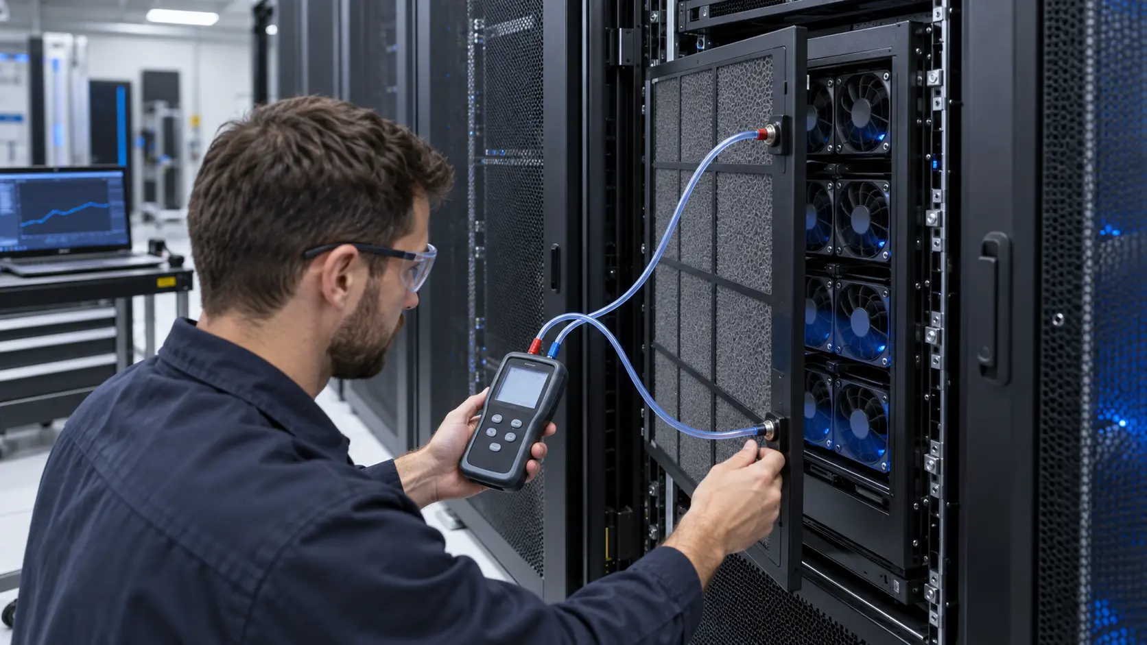
The operator compared pressure drop across the filter, inlet temperature, fan command, current and rack load. A pressure limit was used as an early maintenance signal, while thermal margin and airflow confirmed whether the limit was conservative enough for the actual server.
An illustrative trigger might be a persistent 100 Pa increase from the clean baseline, or a defined percentage of the available pressure margin. Those numbers are examples only. The correct trigger depends on filter media, fan curve, rack duty and the operator's risk tolerance.
The service procedure also checked the seal after replacement. A new filter with a bypass gap can create contamination risk while showing an unexpectedly low pressure drop. Pressure alone must therefore be interpreted with airflow, visual inspection and thermal evidence.
Validation Result: The Filter Became a Designed Operating State
The final sample package showed when the fan, filter or maintenance plan was the limiting element.
The release record documented filter type and area, clean and loaded pressure drop, fan P-Q points, PWM/FG/RD response, airflow, inlet temperatures, rack power, acoustic condition, seal inspection and service trigger. It separated illustrative estimates from customer acceptance values.
The transferable lesson is that a fan selected on a clean rack can fail in service without any electrical fault. The installed pressure path must include the filter condition expected before maintenance, and the operator must have a measurable trigger before thermal margin is consumed.
For procurement, compare candidates at the loaded pressure and required airflow. Ask for the P-Q curve, the test basis, control behavior, life assumption and sample validation plan instead of accepting a maximum CFM headline.
How MEGA Tech Supports AI Server Fan and Filter Validation
MEGA Tech helps server and rack integrators match custom DC fans to the loaded air path and the service plan.
We can review compact DC axial fans and blowers, filter and grille losses, tray pressure, PWM and FG/RD signals, connector details, vibration, acoustic limits, bearing and life targets, and small first-build quantities. We can also evaluate alternatives to Sanyo Denki, SUNON, Delta, NMB, ebm-papst and other installed brands when the operating point is defined.
Please provide rack or chassis heat load, airflow and static pressure at that airflow, filter type and area, clean and final pressure-drop basis, temperature and altitude, fan size, voltage, quantity, control interface, connector, noise target, service interval, environment and life assumption.
Our scope is fan and air-path engineering, sample customization and comparative validation. We do not supply the customer's server firmware, DCIM/BMS, CRAH/CRAC, filtration policy or facility safety design.
Engineer Questions About This Filter-Loading Case
Use these questions before approving a fan, filter or maintenance interval for an AI server rack.
Q: Does a higher RPM prove the filter is still acceptable? A: No. Check installed airflow, pressure, inlet temperature and current at the loaded condition.
Q: Should I select the highest-static-pressure fan? A: Not automatically. Balance pressure margin with power, noise, bearing life, filter area and service requirements.
Q: Can a lower pressure drop mean a better filter condition? A: Not if the filter seal is bypassing. Inspect the installation and correlate pressure with airflow and contamination control.
Q: Is a calendar replacement schedule enough? A: Measure pressure and confirm thermal behavior. A site with different dust loading may need a different interval.
Q: What should I send for a review? A: Send heat load, airflow and pressure, filter data, fan size, voltage, quantity, control, noise, environment and life target.
Q: Can MEGA Tech provide a custom sample? A: Yes. We can review the loaded duty and support a sample comparison before production release.
Need an AI Server Fan and Filter-Margin Review?
Send the rack heat load, installed airflow and static pressure, fan size, voltage, filter type and area, clean and loaded pressure-drop basis, noise target and maintenance constraints. MEGA Tech will review the operating point before recommending a sample.
Include the current fan model, fan-tray photos, rack layout, filter data, workload profile, inlet-temperature measurements and any pressure or maintenance history available. This helps separate a fan problem from a filter, seal, sensor or facility-airflow problem before the production BOM is locked.