The Rear Door Was Removing Heat — and Adding a New Airflow Problem
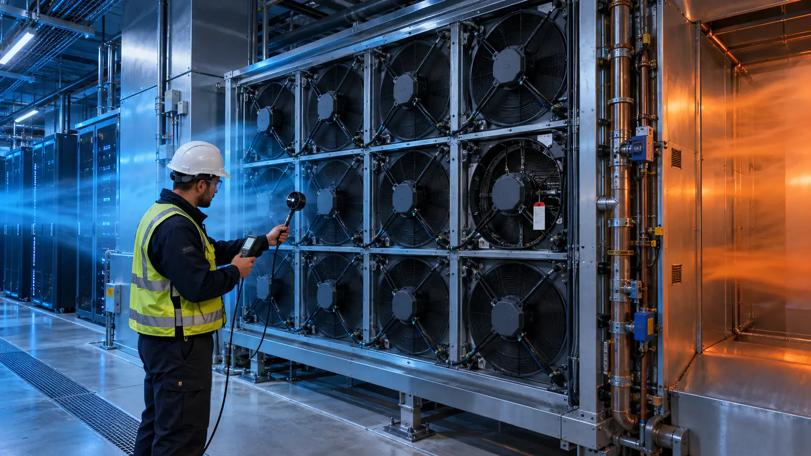
An anonymized North American AI-infrastructure integrator needed an active rear-door heat exchanger (RDHx) for high-density racks. The coil captured exhaust heat, but the added air-side resistance changed the server fan duty and made the door fan selection uncertain.
The rack passed a short thermal demonstration with a passive door. During a longer AI workload, however, the server fans increased speed, the rear-door differential pressure moved away from neutral and the room-side sound level became difficult to predict. The team did not want to solve the problem by simply adding more fan RPM: that could raise server fan power, acoustics and pressure interaction at the rack boundary.
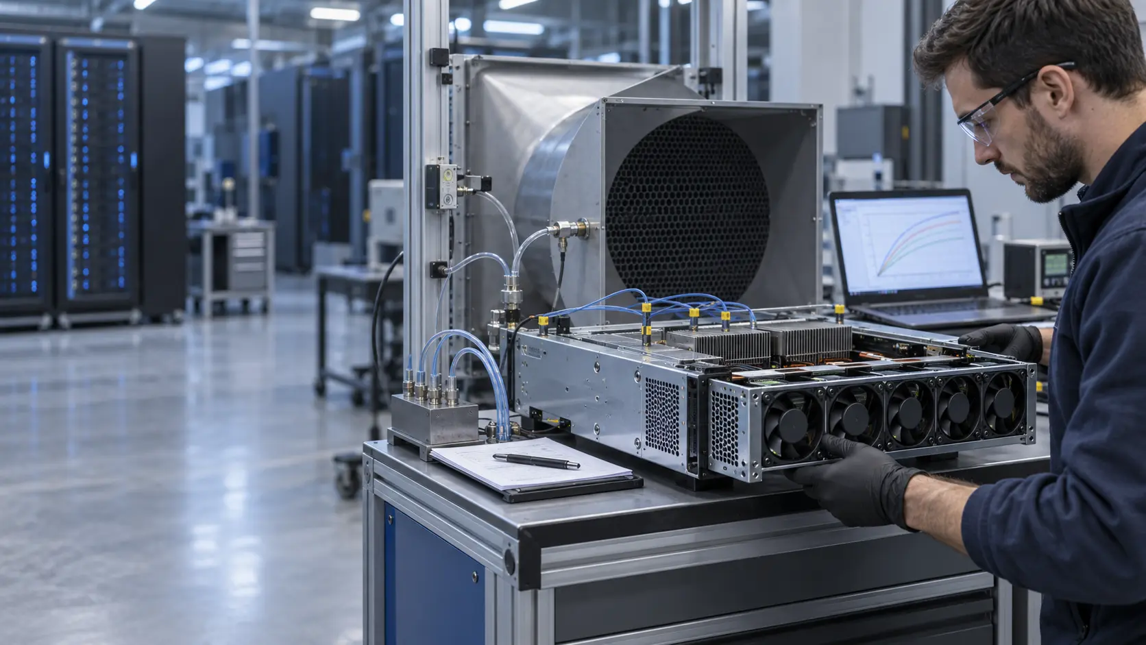
MEGA Tech reviewed the customer's rear-door envelope, heat-exchanger pressure-drop data, server fan behavior and control interface. The goal was a validated active-fan sample that assisted the rack without starving the servers, maintained useful airflow when one fan was unavailable and remained serviceable inside a shallow door.
The customer name, rack make and released acceptance values remain confidential. This case describes the engineering workflow and the calculations that should be repeated on the assembled door, not a universal RDHx performance claim.
The Engineering Hook: A Liquid Coil Still Needs the Right Airflow
Water removes heat from the coil, but the server exhaust still has to cross the fins. The fan is an air-side operating-point problem before it is a catalogue problem.
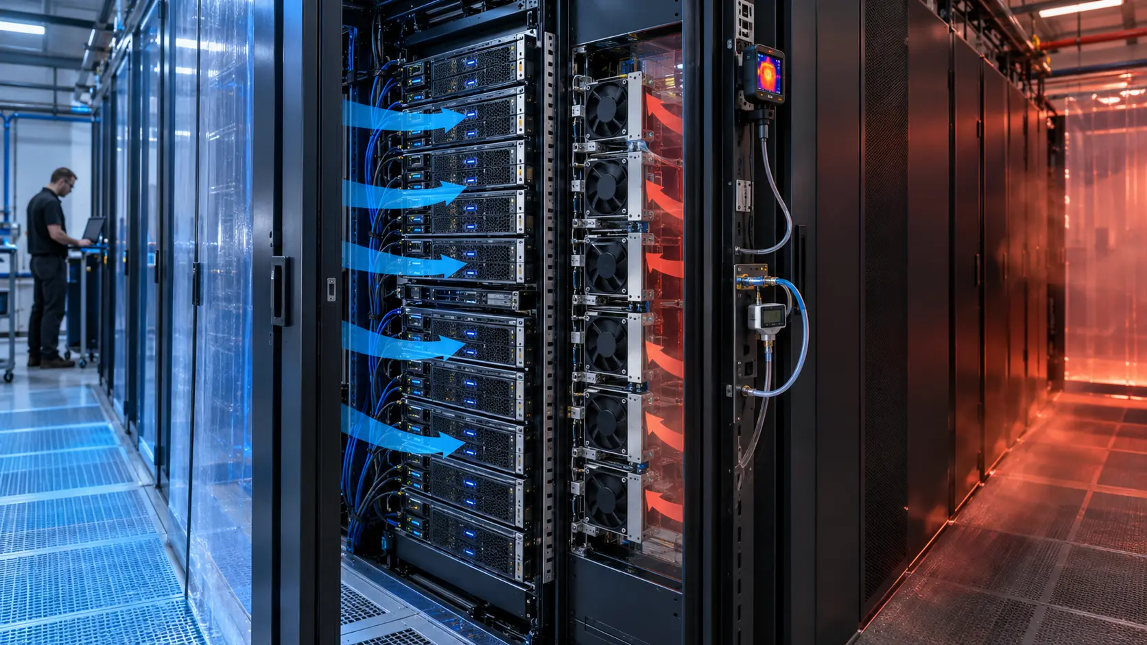
A rear-door heat exchanger replaces or supplements the rack door and intercepts warm exhaust before it mixes into the room. A passive door relies on server fans; an active door adds its own fans. Neither architecture is automatically better. The correct choice depends on rack airflow, coil pressure drop, available depth, server fan margin, controls, service access and the required failure behavior.
The Open Compute Project's open-rack door heat-exchanger requirements emphasize fan curves or tables that correspond to the actual fan operating condition and a complete door pressure-drop assessment. Industry guidance also describes the key interaction: an active door should move approximately the server exhaust flow, while too much suction can disturb server inlet conditions and too little assistance can leave heat spill at the rack boundary.
That interaction is why a headline CFM value is not enough. The fan must be selected against the door's coil, grille, filter if present, bends and discharge path. The installed intersection of the fan curve and the door system curve is the value that matters.
The Problem in Operation: The Door Was Not Pressure Neutral Across the Load Range
The prototype was close to neutral at one test point, but the result changed when the AI workload, server fan command and coil resistance changed together.
At low rack load, the active door fans could pull more air than the servers were supplying. At higher load, the server fans increased airflow and the coil became the dominant restriction. The same fixed door-fan command therefore produced different pressure relationships in different states. The team needed a control envelope, not a single balancing number.
The first review separated four measurements: rack exhaust airflow, pressure upstream of the coil, pressure downstream of the door and fan electrical input. A fifth measurement tracked the server fan command or telemetry when available. Without this separation, a lower outlet temperature could look like improvement even if the server fans were working harder and the rack was consuming more energy.
The acceptance question became practical: can the door capture the intended exhaust at representative load, avoid reverse flow at low load, and recover an acceptable thermal and acoustic condition after one door fan is unavailable? Those questions were answered with an assembled sample, not a spreadsheet-only selection.
Interactive: Watch the Operating Point Move With the Door Load
The animated schematic is qualitative, but it shows the control problem engineers should test: a fan array must follow rack exhaust while coil resistance and server duty move.
The intended control target is usually close to neutral pressure across the rack boundary, not maximum door airflow. The actual target must be defined by the rack and door manufacturer. A production implementation may use rack airflow, differential pressure, server telemetry, door temperature or a coordinated combination.
For the test, the team used idle, representative AI load, high-load step and one-fan-unavailable states. Each state recorded coil inlet and outlet temperature, pressure differential, total airflow, fan command, RPM or FG, current, sound pressure and server thermal telemetry. The animation does not replace those measurements; it helps the design team see why one PWM command cannot represent the full door duty.

Sample 01: Start With the Coil Curve and the Door Envelope
The fan sample was chosen only after the heat-exchanger assembly and service constraints were frozen enough to represent the installed path.
The integrator supplied coil pressure-drop data, the target rack airflow, door depth, fan cut-out, grille details, water-side operating range, control voltage and acoustic limit. MEGA Tech compared compact high-static-pressure EC axial candidates and evaluated whether the fan could be mounted in a shallow array without reducing service access.
A simple planning estimate illustrates the scale. If a 50 kW rack rejects heat at an assumed 15 K air rise, Qv = P/(rho x cp x deltaT) gives approximately 2.78 m3/s, or about 5,900 CFM, before accounting for nonuniformity, recirculation, leakage and the actual heat exchanger effectiveness. This is a sizing estimate only; the installed rack airflow and vendor coil data must govern the selection.
The review also checked door weight, hinge torque, cable bend radius, fan guard, connector access, condensation boundaries and the possibility of reverse airflow when adjacent racks or server fans create a pressure difference. A fan that fits the cut-out but changes door mechanics is not a production-ready sample.
Sample 02: Tune the Array for Near-Neutral Pressure and N+1
The design target was not the highest possible pressure. It was enough pressure to move the required exhaust through the coil while preserving server airflow and a predictable failure response.
The candidate array was tested in the installed door at several commands. The team plotted the measured door system resistance and compared the fan-array operating point with the server exhaust available at each rack state. The normal control curve was then adjusted so the door did not over-pull at idle or fall behind at the high-load step.
For N+1, one fan was disabled under a controlled test condition. The remaining fans were not assumed to deliver the same total flow automatically: the array curve changed, local velocity distribution changed and the pressure balance moved. The result was recorded as a degraded operating state with its own thermal, acoustic and current values.
The electrical tradeoff was also explicit. For example, a 24 V EC fan drawing 1.2 A consumes about 28.8 W at the stated condition; six such fans would draw about 173 W before controller and conversion losses. If the normal command reduces each fan to 0.75 A, the fan-array input is about 108 W. These are illustrative arithmetic checks, not the customer's measured values, and should be replaced with the selected fan's actual data.
Sample 03: Validate Sound, Vibration and Service Access
A door fan can meet airflow targets and still fail the deployment because it adds tonal noise, vibration or an unacceptable maintenance burden.
The acoustic review separated broad airflow noise from blade-pass or motor tones and from vibration transferred into the door frame. The test was repeated at the rack boundary and in the operator area because the same fan can sound different after the coil, grille and enclosure are installed.
The mechanical review included fan-to-panel sealing, fastener preload, connector retention, door opening, filter or coil inspection and the effect of a fan fault on the remaining modules. The team also checked warm restart after a controller reset and verified that the fan signal did not create an unexpected full-speed event during a service operation.
These checks matter for buyers because a small reduction in fan unit price is not a saving if the door requires rework, produces an avoidable acoustic complaint or makes coil cleaning difficult. The custom sample should reduce integration risk before the production BOM is locked.
Validation Result: The Sample Protected Rack Airflow Without Hiding the Energy Cost
The final sample gave the integrator a controlled fan curve and a repeatable commissioning method instead of a single catalogue headline.
The validated configuration maintained the intended airflow relationship across the defined rack states, documented the pressure behavior with the coil installed and gave the controls team a normal curve plus a one-fan-unavailable response. The result was not described as a universal rack capacity because the coil, server population, water condition and containment arrangement remain application-specific.
The transferable lesson is simple: active RDHx fans should be selected from the complete air path and coordinated with server airflow. The selection package should include a fan curve at the specified voltage, control behavior, FG or alarm details, acoustic test condition, mounting drawing, sample test data and a failure-state recommendation.
If the door has not yet been built, start with the coil pressure-drop curve, rack exhaust target, available depth, fan quantity, voltage, control range and service constraints. If the door already exists, send the installed photos and measured pressure points. Both are enough for a first engineering review.
How MEGA Tech Supports Active RDHx and Data-Center Fan Customization
MEGA Tech develops custom cooling-fan samples around the customer's rack boundary, pressure target and mechanical envelope rather than treating a catalogue CFM as the design answer.
We can review compact EC axial or centrifugal fan directions, voltage and PWM requirements, FG or RD feedback, connector and mounting details, bearing and life targets, acoustic limits, IP or contamination concerns and sample quantity. Where a named-brand fan is already installed, we can evaluate a replacement against frame size, airflow, static pressure, controls and the actual system curve.
Our role is the fan and air-path engineering: fan selection, customization, sample tuning, comparative testing and documentation. The rack integrator and facility team remain responsible for the server, coil, water loop, controls, containment, commissioning limits and site safety. That boundary keeps the case technically credible and makes the next engineering decision clear.
Need a product starting point? Browse the MEGA Tech cooling-fan selection and product information, then send the existing fan model or the P-Q/system data. We can tell you which information is missing before recommending a sample.
Engineer Questions About This Active RDHx Case
These are the questions we would put on a design-review checklist before approving a fan array or a door control curve.
Q: Do all rear-door heat exchangers need fan assistance? A: No. Passive and active doors are both valid architectures. The decision depends on coil pressure drop, server-fan margin, rack density, acoustic limit, redundancy and facility integration.
Q: What does near-neutral pressure mean here? A: It means the door is not materially starving the server exhaust path or pulling uncontrolled room air through the rack at the defined operating state. The project must define the measurement locations and allowable range.
Q: Can N+1 be proven from the normal fan curve? A: No. Disable one fan or use an approved fault simulation and measure the new array operating point, temperature, pressure, sound and control response.
Q: What should I send for a custom fan review? A: Send the coil pressure-drop curve, rack airflow or server fan duty, door depth and cut-out, voltage, PWM/FG/RD needs, acoustic target, ambient conditions, fan quantity and service constraints.
Q: Can MEGA Tech provide a P-Q curve or custom specification? A: Yes, after the operating point and sample configuration are defined. A preliminary review can start from an existing fan part number, a drawing, a measured pressure point or an installed photo.
Need a Fan Curve or Custom Specification for Your Door?
Send the rack airflow target, coil pressure drop, door depth, fan quantity, voltage, control range and acoustic limit. We will review the installed operating point and tell you what should be tested before the BOM is locked.
Use the product information page for a starting point, or contact MEGA Tech directly for a custom sample review. Include the current fan model, P-Q curve, rack photos or a simple pressure map if those are available. The more clearly the installed air path is defined, the faster we can separate a fan problem from a coil, grille, sealing or control problem.