The Farm Dashboard Can Look Stable While the Crop Zone Is Not
Average room temperature and humidity do not prove that every shelf has the same leaf-level environment.
A multi-layer vertical farm may report a stable room temperature, relative humidity and CO2 value while crops on different shelves experience different air movement, leaf temperature and moisture removal. The upper layer may receive warmer air from LED fixtures and buoyancy, the lower layer may sit in a stagnant pocket, and the first shelf near a fan may dry faster than the far end. The result can be uneven growth, edge damage, condensation or disease pressure even though the central controller shows a normal average.
Air movement is not only a cooling requirement. It changes the boundary layer around the leaf, affects sensible and latent heat transfer, and influences the local vapour-pressure deficit. A fan that blows directly at one crop row may create a strong local jet while leaving other rows under-supplied. A larger fan at the room level may mix the aisle but fail to deliver useful velocity through dense canopies and narrow rack gaps.
This article follows an anonymized European vertical-farm retrofit scenario. The numbers in the example are engineering estimates used to show the method, not a published customer result. The objective is to demonstrate how a farm team can map leaf-level airflow, LED heat, VPD and pressure, then choose between a sidewall axial fan, rack-mounted axial fans, a compact blower or a custom PWM fan array.
Anonymized Retrofit Brief: Three Racks, One Average Sensor
The first design mistake was treating a room sensor as a crop-zone map.
The example facility used three rack banks with five growing levels. LED fixtures were installed below each shelf, irrigation ran on a repeated cycle, and the climate controller measured air temperature and relative humidity near the aisle return. Operators reported that the front rows were drying faster than the rear rows and that the upper level showed more leaf-temperature variation after the lights reached full output. The room average remained inside the operating recipe, so a higher total fan rating was initially proposed.
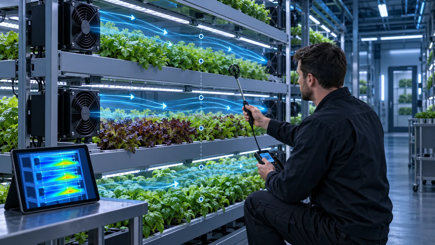
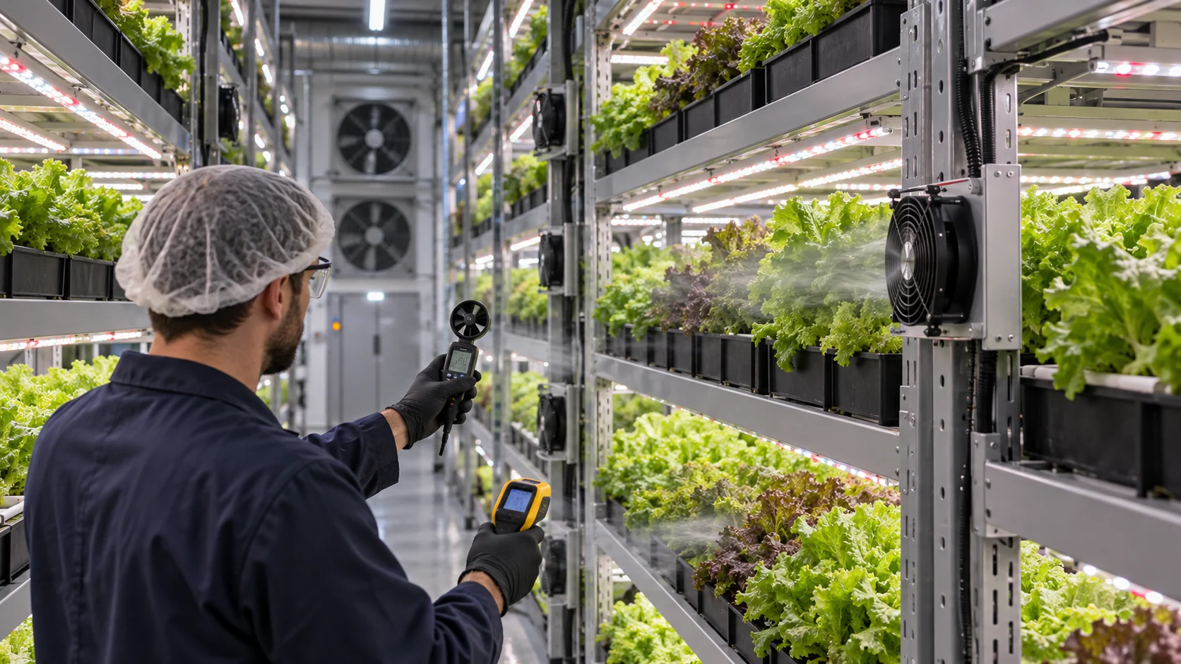
Before changing the fan, the engineering team placed an anemometer grid at the front, centre and rear of each rack level. They also logged leaf or canopy temperature, air temperature, relative humidity, light state, irrigation state and fan command. The map showed a high-velocity zone close to the existing side fan, a low-flow pocket behind the rack uprights and a warmer upper return path. This pattern indicated distribution and bypass problems rather than a simple shortage of total room airflow.
The lesson is transferable: measure at the crop zone and at the operating states that matter. If the only sensor is near the return air, the control loop may increase or decrease fan speed without knowing whether the canopy is actually receiving uniform air movement. A fan supplier can help with fan pressure, flow and control, but the crop recipe and agronomic acceptance limits must be defined by the farm team.
Animated Model: Rack Airflow, LED Heat and the Leaf Boundary Layer
The useful question is where air reaches the canopy, not how much air the room fan moves in free space.
The animation compares two common layouts. In the first, a sidewall fan creates a strong jet that passes the first rack but loses momentum and leaves a low-flow zone behind the shelf structure. In the second, smaller distributed fans or a controlled plenum introduce air closer to each crop layer, reducing the distance between the fan and the canopy. The best arrangement depends on rack geometry, pressure loss, crop density, noise, service access and the climate-control boundary.
The particles are not a CFD result and do not specify a universal leaf velocity. Use them to structure a test plan: measure a grid at several heights and shelf positions, repeat with young and mature canopy, and record LED state, irrigation state, fan command and climate data. A useful map should show both mean velocity and variation. A high mean value at one point does not compensate for a stagnant area at another.
If the fan is too close or the outlet is poorly shaped, a direct jet can dry or mechanically stress the front crop. If the fan is too far away, the flow can bypass the canopy or recirculate in the aisle. A short diffuser, baffle or controlled outlet can be more effective than simply adding RPM.

Calculate the Sensible Heat Before Choosing Fan Capacity
LED power becomes heat somewhere in the farm boundary, but the fan is not automatically the right device to remove all of it.
Estimate how much LED and driver power enters the air near the rack. Some heat is transferred to the room, some is absorbed by leaves and structure, and some is removed through the HVAC or dehumidification system. A circulation fan redistributes heat and moisture; it does not remove them from the building unless the air path reaches a heat-rejection boundary.
For a screening example, assume one rack bank has 4.5 kW of LED and driver heat entering the conditioned air, and the design uses a 6 K local air-temperature rise as a comparison point. With rho = 1.2 kg/m³ and cp = 1,005 J/(kg·K), the ideal air movement associated with that sensible load is about 2,239 m³/h. This is not a crop-zone fan selection because the room HVAC, rack geometry, latent load and recirculation determine the final system. It shows why a small shelf fan cannot be judged against the full LED power as if it were the only cooling device.
The fan selection should state its job. A rack fan may provide local mixing and boundary-layer control. A sidewall or aisle fan may move air through a larger zone. An exhaust or HVAC fan may reject sensible and latent heat. Confusing these functions leads to oversized circulation fans, poor VPD control and unnecessary energy use.
Use Leaf-Level Measurements, Not Only Room Averages
Uniformity must be measured where the crop responds: across the canopy, along the shelf and between levels.
Build a measurement grid that includes the air entering the crop, the centre of the canopy, the rear of the shelf and the return path. For each location record air temperature, relative humidity, local velocity and, where practical, leaf or canopy surface temperature. Repeat at the top, middle and bottom layers. Include the front and rear of the rack because the inlet jet often creates the largest gradient there.
Calculate the mean, minimum, maximum and spread for each layer rather than reporting one average. A simple uniformity index can be defined for the farm’s internal comparison, but do not present it as a universal crop standard. The acceptance limit should be connected to the crop recipe, disease-risk policy, irrigation state and agronomic outcome. A crop engineer may decide that a lower velocity is acceptable during rooting and a different distribution is needed during mature canopy.
Sensor placement can mislead the control loop. A humidity probe in the aisle may not represent the leaf boundary layer. A temperature probe beside a fan may read a cool jet. A single return sensor may respond after a hotspot has already developed. Pair fixed sensors with temporary grids or thermal imaging during commissioning, then select permanent sensor locations from the observed field.
| Measurement | Why it matters | Recommended comparison |
|---|---|---|
| Leaf or canopy temperature | Connects heat and evaporative response to crop condition | Front, centre and rear of each representative layer |
| Local air velocity | Shows boundary-layer and mixing differences | Multiple points at canopy height, not only aisle centre |
| Air temperature and RH | Supports local VPD calculation and condensation review | Inlet, canopy, rear shelf and return air |
| Fan pressure and command | Shows whether the fan reaches its installed duty | Clean path, loaded path and each control state |
| Energy and sound | Prevents uniformity gains from creating an unacceptable operating cost or noise burden | Same crop recipe and lighting state |
Choose the Fan Architecture from Rack Geometry
The right fan type depends on distance, pressure, distribution and service access.
A sidewall axial fan can be efficient when it pushes a long, open cross-flow through the aisle and the rack faces are not heavily blocked. It needs a clear inlet, a controlled outlet and enough throw to reach the far end. A larger frame at moderate speed may reduce noise and energy, but it will not automatically solve a bypass path around the crop racks.
Rack-mounted axial fans are useful when each layer needs a shorter air path and a more direct control zone. The fan must be protected from irrigation spray, leaves, cleaning and accidental contact. Multiple small fans also create more connectors, alarms and maintenance points, so the control and service design should be simple and accessible.
A compact blower becomes useful when the design requires a narrow plenum, filter, diffuser or duct with meaningful static pressure. It can feed a controlled air path through several shelf openings, but the outlet geometry and acoustic result need validation. For small farms and new crop trials, MEGA Tech can provide custom fan samples with different frame sizes, pressure levels, PWM curves, FG feedback, connectors and mounting details before a production layout is fixed.
- Use a larger low-speed axial fan when the path is open and the goal is aisle mixing.
- Use distributed axial fans when each layer needs local airflow and service access is manageable.
- Use a compact blower when a plenum, filter or diffuser creates higher static pressure.
- Use PWM and FG when the climate controller must adapt airflow without running every fan at full speed.
- Use a custom sample when rack geometry, connector, noise or crop-zone uniformity cannot be met by a catalogue fan.
VPD and Condensation: Avoid Solving One Problem by Creating Another
Increasing air speed changes evaporation and leaf temperature, so the fan setting must be evaluated with humidity and dew point.
VPD is affected by air temperature, relative humidity and leaf temperature. If a fan increases evaporation around the front crop but the rear canopy remains stagnant, the local VPD distribution becomes uneven. If a cold HVAC jet reaches a humid leaf surface, the risk can move from poor drying to condensation. The controller should not use one room-average VPD value as proof that every shelf is safe.
For a practical trial, record air temperature and RH at the crop zone, then measure representative leaf temperature rather than assuming it equals room air. Compare the local VPD and leaf-to-air temperature difference before and after a fan change. The exact acceptable range depends on the crop and growth stage; the fan supplier should not prescribe an agronomic setpoint without the farm’s crop team.
Check humidifier, irrigation, light and fan transitions together. A fan that starts at the same instant as misting may move droplets onto leaves or sensors. A fan that stops during a low-light state may allow a stagnant humid pocket. Minimum circulation, staged fan control and a dew-point margin can be evaluated, but the control algorithm must be validated against the actual farm boundary and crop response.
Anonymized Retrofit Validation: Change Distribution Before Fan Count
The example team tested a layout change before installing more total fan power.
In the example retrofit, the first proposal added more fans at the aisle end. The engineering review instead tested a sidewall source with a short diffuser and two smaller rack-level assist fans at the upper layers, where the initial map showed the largest velocity variation. The fan samples were operated at several PWM commands and measured with the same anemometer grid used for the baseline.
The comparison tracked four outputs: canopy velocity spread, leaf-temperature spread, fan electrical energy and acoustic level at the operator position. The team also tested the clean and partially restricted intake path. This matters because a diffuser, mesh or filter can move the fan operating point and change the result. The chosen configuration was not approved from a room-average temperature; it was approved after the crop-zone map became more uniform without creating a high-speed jet at the front row.
The transferable lesson is that fan count is not the same as airflow quality. More fans can increase turbulence, sound, heat and service effort while leaving a bypass route untouched. A custom fan supplier can help produce and compare samples, but the farm should own the crop acceptance criteria and confirm the result across the intended growth stages.
How MEGA Tech Supports a Custom Vertical-Farm Fan
We help convert rack geometry and crop-zone measurements into a fan sample that can be tested before production.
MEGA Tech can evaluate custom axial fans, compact blowers, distributed rack fan assemblies and PWM-controlled fan arrays for vertical farms, plant factories and controlled-environment agriculture equipment. We review the rack spacing, shelf length, crop density, LED heat, target airflow, pressure loss, humidity, irrigation exposure, noise, voltage, control interface, FG feedback, service interval and quantity. The recommendation may be a single larger fan, several moderate-speed fans or a blower feeding a defined plenum.
For a first review, send rack drawings or photographs, shelf dimensions, crop and growth stage, LED power by layer, measured velocity map, air temperature and RH, fan location, filter or grille details, voltage, desired control, acoustic position and prototype quantity. If you are replacing Sanyo Denki, SUNON, Delta, NMB, ebm-papst or another established fan, send the part number and the installed working point. We can compare the performance envelope and produce samples for fit and crop-zone validation.
Our support includes parameter adjustment, sample matching, P-Q characterization, PWM/FG customization, connector and wire changes, low-volume prototypes and production transition. We do not replace the farm’s agronomic validation or HVAC design responsibility. The final approval should connect fan performance to measured crop-zone uniformity, energy, sound, humidity and maintenance conditions.
Engineer FAQ: Vertical-Farm Airflow and Fan Selection
Short answers for farm operators, HVAC engineers and fan procurement teams.
Q: Is higher CFM always better for crops? A: No. The useful result is uniform, controlled canopy airflow at acceptable sound, energy, humidity and leaf-temperature conditions.
Q: Why can the room sensor look normal while plants perform unevenly? A: A room sensor averages a large volume and may miss layer-to-layer velocity, temperature, humidity and leaf-boundary differences.
Q: Should I use one large fan or many small fans? A: Compare installed pressure, throw, distribution, energy, sound, redundancy and service. Fan count alone does not define uniformity.
Q: What fan is suitable for a narrow rack plenum? A: A compact high-static axial fan or centrifugal blower may be a better starting point than an open-air axial fan, but the installed pressure curve must be measured.
Q: Does PWM help vertical farms? A: Yes, when airflow should follow light, crop stage or humidity state. Validate low-duty startup, feedback and the response to irrigation and lighting transitions.
Q: Can MEGA Tech make samples for a small farm project? A: Yes. We can adjust fan size, pressure, control, connector and mounting for a measured prototype requirement before production quantities are fixed.
Vertical-Farm Fan Design-Review Checklist
Use this checklist before increasing fan count or releasing a new rack layout.
- Have velocity and temperature been measured at the crop zone on every representative shelf?
- Are leaf or canopy temperatures measured, rather than inferred from the room sensor?
- Which heat is handled by rack circulation fans and which heat is rejected by HVAC or dehumidification?
- Does the fan path include rack uprights, crop density, filters, diffusers, mesh and cable routing?
- Have front-to-rear bypass and stagnant zones been mapped before adding more fans?
- What happens to VPD, condensation risk and leaf temperature during irrigation and lighting transitions?
- Does the chosen fan still meet the working point at the service-limit filter or grille condition?
- Are PWM, FG, noise, energy, cleaning, water exposure and connector service requirements defined?
- Is the acceptance criterion based on crop-zone uniformity and maintenance state, not only room-average temperature?
- Has a production-intent sample been tested with the actual rack, crop density and LED state?