The Robot Cabinet Can Pass Idle and Fail During Motion
A robot controller enclosure is not cooled by its average electrical load; the most demanding motion sequence can set the fan and filter requirement.
A robot cell may look thermally comfortable while the arm is parked, then fault when several axes accelerate, decelerate and reverse repeatedly. The controller cabinet contains servo amplifiers, power supplies, contactors, braking components and control electronics. Their losses change with current, switching frequency, regenerative braking and duty cycle. The cabinet fan must move heat through the final filter, grille, cable path and internal component arrangement, not through an ideal open-air test.
The first mistake is selecting a fan from the controller's nameplate power or from a free-air CFM headline. The second is using a steady-state cabinet temperature while ignoring the peak-motion sequence. A servo drive may be rated at a 40°C ambient and require derating above that point; the allowable current can change with temperature, altitude and installation. Beckhoff, Kollmorgen and other drive documentation treat ventilation and environmental conditions as part of the drive installation, not as an optional accessory.
This article gives a repeatable method for converting motion duty into heat load, pressure and airflow requirements. It also shows where a custom fan, filter alarm, temperature sensor or enclosure layout change can prevent a nuisance over-temperature fault without simply increasing RPM everywhere.
Build the Heat Budget from the Motion Profile
Use actual losses where available and separate continuous heat from short regenerative peaks.
Start with the loss values from the servo-drive and controller documentation. Add power-supply loss, braking-resistor loss that is actually transferred into the cabinet, contactor and transformer loss, control electronics, and any fan or filter-heater power. If a datasheet provides only efficiency, estimate loss as input power minus delivered output power at the relevant operating point. Do not add the motor's mechanical output power as cabinet heat unless the motor or brake is physically inside the enclosure.
For motion equipment, record at least three states: parked or idle, continuous production cycle and worst short sequence. The worst short sequence may not set the steady cabinet temperature, but it can set the drive junction or heat-sink temperature. A temperature logger at the drive inlet and heat sink, synchronized with axis current and braking events, reveals whether the cabinet is limited by accumulated heat or by a short transient.
A practical example is a cabinet with 160 W of continuous electronics loss and a 90 W peak loss from braking and power conversion during a repeated 30-second motion cycle. If the peak repeats often enough that the cabinet does not return to its baseline, size the airflow for the cycle-average heat plus margin and verify the short peak with transient testing. If the peak is isolated, the fan may not need to remove the full 250 W continuously, but the drive heat sink and alarm threshold still need a transient margin.
| State | What to record | Why it matters |
|---|---|---|
| Idle / parked | Cabinet loss, inlet temperature and fan duty | Finds minimum control duty and baseline heat |
| Normal cycle | Axis current, drive loss, cabinet temperature and filter pressure | Represents production operation |
| Peak motion | Acceleration, deceleration, brake events and heat-sink slope | Finds short thermal margin |
| Loaded filter | Differential pressure and useful airflow at service limit | Prevents clean-filter overconfidence |
Animated Model: Peak Heat and Filter Pressure Move the Duty Point
The moving particles compare a clean-filter cabinet with a loaded-filter cabinet during a high-motion sequence.
In the clean state, the fan moves air through the intake filter, across the servo-drive heat sinks and out of the exhaust. In the loaded state, the filter and grille consume more pressure, so the same PWM command produces less useful airflow. The drive may still report a normal fan RPM, but the heat sink receives less cooling air and the cabinet temperature rises during the motion cycle.
The animation is not a CFD result or a universal filter multiplier. Use it to define the test: measure filter differential pressure, fan command, fan feedback, cabinet inlet temperature, heat-sink temperature and useful airflow at clean and service-limit conditions. The fan should be selected against the installed pressure, not against the clean fan inlet alone.

Calculate Required Airflow Without Losing the Pressure Check
A heat-balance estimate gives a starting airflow; the fan P-Q curve decides whether that airflow exists through the cabinet.
For a ventilated cabinet, a useful first estimate is Qv ≈ P / (rho x cp x delta-T), where P is heat in watts, rho is air density, cp is air heat capacity and delta-T is the allowed air-temperature rise. Using standard air and a 10 K rise, 250 W requires roughly 75 m3/h, or about 44 CFM, before losses and margin. This is an estimate, not a fan specification.
If the final filter, grille, heat sinks and cabinet path require 80 Pa at 75 m3/h, the selected fan must deliver that operating point. A fan rated at 75 m3/h in free air may deliver much less at 80 Pa. Add the pressure drop of the service-limit filter and any narrow internal passage. If the filter pressure rises from 20 Pa clean to 55 Pa loaded, the fan operating point moves even if the motor command remains unchanged.
Use a margin that is tied to uncertainty, not a universal multiplier. If the heat loss estimate is uncertain by 15%, the filter loading is variable and the sensor tolerance is ±2 K, document those assumptions and validate the worst combination. A larger frame at a lower speed can reduce noise and bearing stress, while a high-static-pressure compact fan may be necessary where the enclosure cannot accept a larger opening.
Filter Placement, Positive Pressure and Contamination
The fan/filter arrangement protects the drive only when the enclosure pressure and maintenance state are understood.
In dusty production areas, a filtered intake can keep the cabinet slightly positive and reduce uncontrolled ingress through cable glands and door gaps. But the filter adds resistance and its pressure rises as dust accumulates. An exhaust-only arrangement can draw contaminated air through every imperfect seal. The correct arrangement depends on enclosure rating, washdown, oil mist, humidity and the permitted air path; it should not be copied from a clean laboratory cabinet.
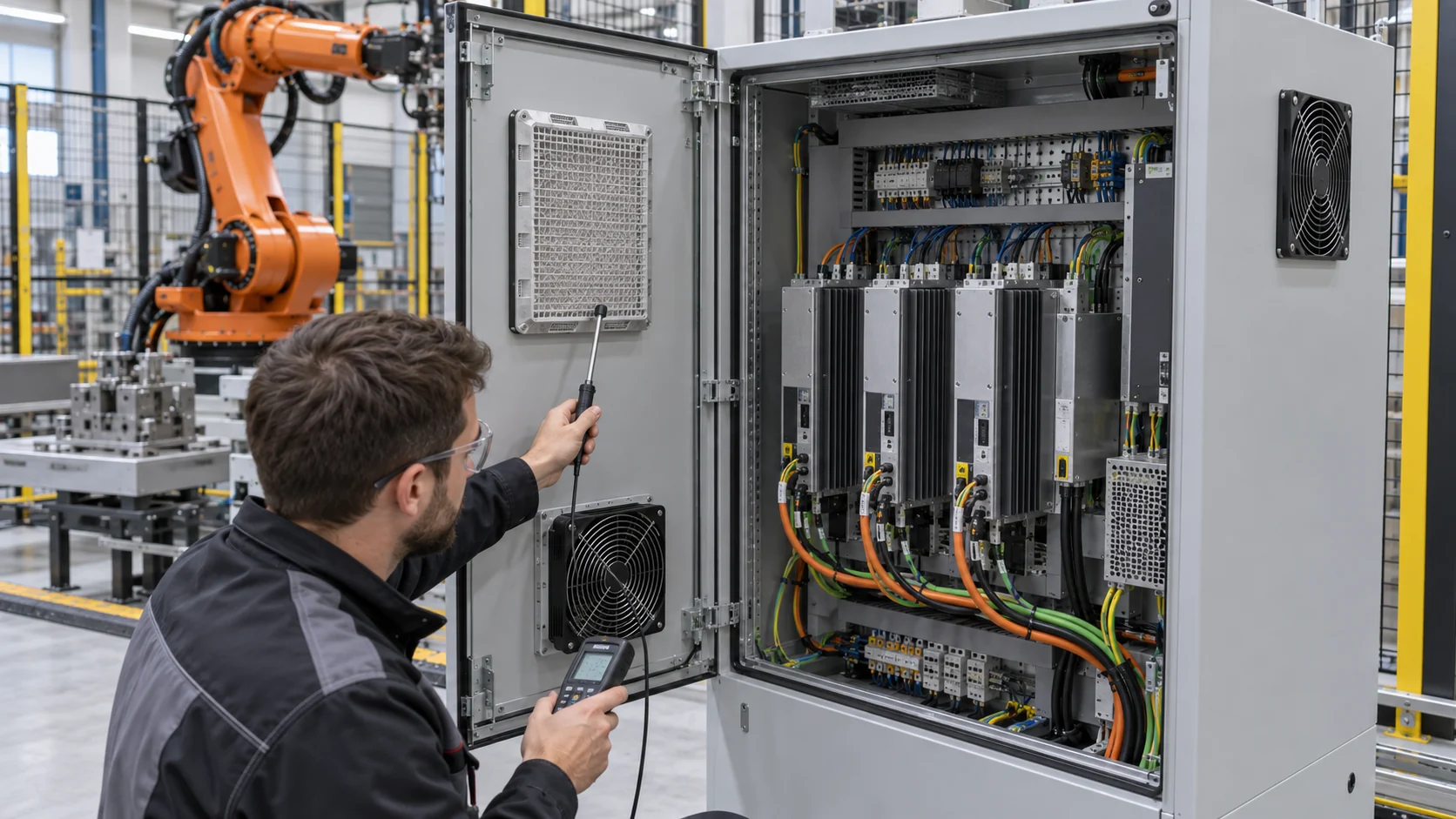
Place a differential-pressure sensor or switch across the filter when a blocked filter can remove the fan's pressure margin. A simple alarm based only on fan RPM can miss this failure because the rotor remains at command speed while airflow collapses. Combine filter pressure, inlet temperature, fan feedback and drive temperature so maintenance is triggered before the drive derates.
Do not make a filter claim without stating the test condition. Filter class, open area, dust type, mounting orientation and service interval all change pressure drop. The fan sample should be tested with the final filter and grille, and the enclosure should be checked for short-circuit flow from intake to exhaust that bypasses the heat sinks.
Peak Motion, Braking Resistors and Sensor Placement
The hottest point may be the drive heat sink or braking component rather than the cabinet air sensor.
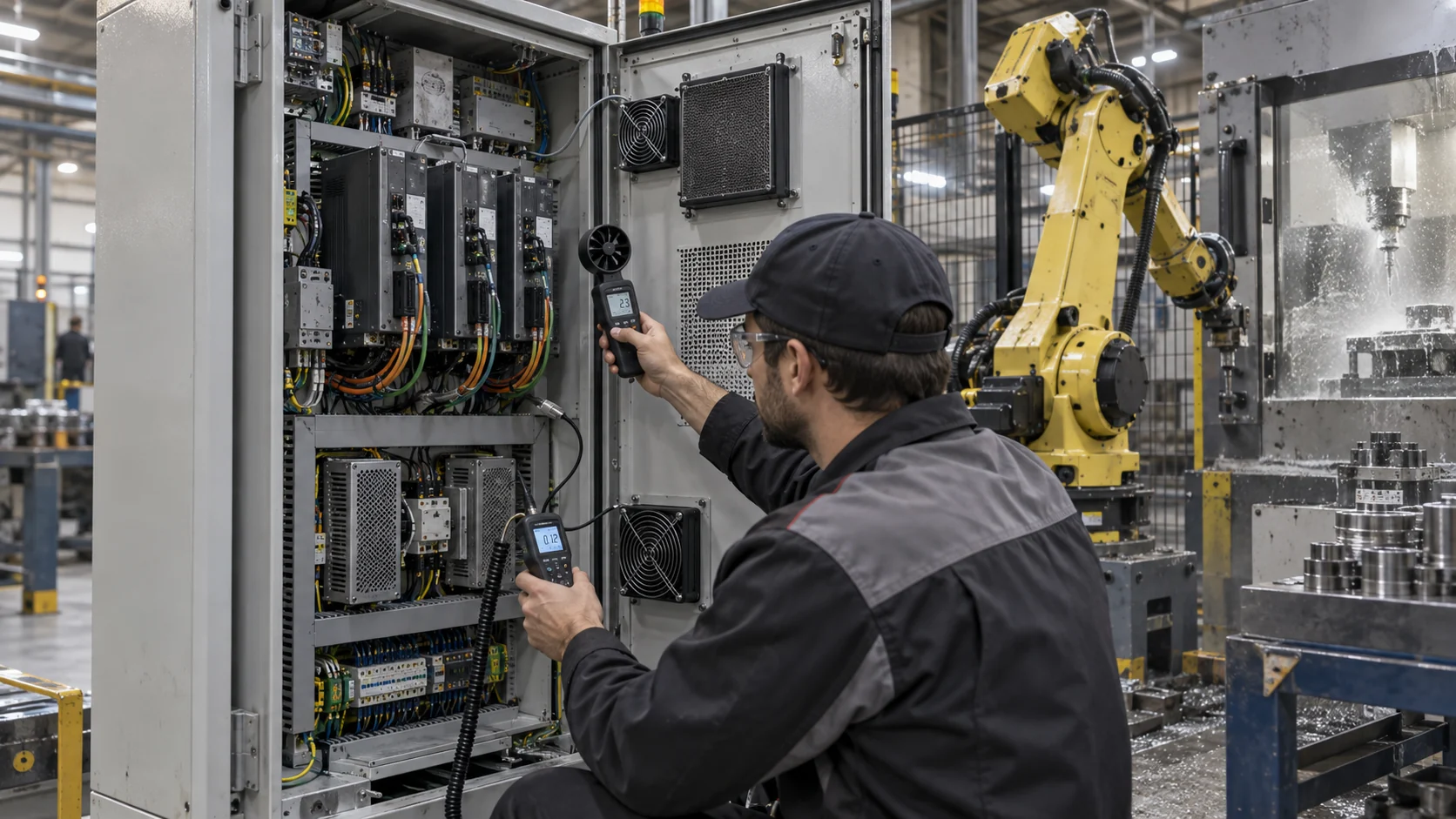
A cabinet air sensor responds slowly and may show an acceptable average while a drive heat sink or braking resistor reaches its limit. Place sensors near the heat source and in the fan inlet path, then compare them with axis current and motion state. The sensor should not sit directly in a fan jet where it reads a local cold spot that does not represent the drive.
During a deceleration event, regenerative energy can be dissipated in a braking resistor or returned to the DC bus. If the resistor is inside the cabinet, its short heat pulse and local radiation need to be included. If it is outside, do not count its mechanical heat in the cabinet budget, but confirm its own cooling and cable routing. The fan control may need a feed-forward step when a known motion sequence begins, followed by temperature feedback.
A useful validation log contains timestamp, axis current, speed, brake command, fan PWM, FG/RD, filter pressure, inlet temperature, drive heat-sink temperature and cabinet exhaust temperature. Without the motion signal, the team may mistake a production-cycle heat pulse for a random fan fault.
Vibration, EMC and Fan Reliability in a Moving Cell
The robot environment adds vibration, cable movement and electrical noise to an otherwise ordinary enclosure-fan problem.
Mount the fan with the approved gasket or isolation hardware and check that the guard, filter frame and cabinet panel do not resonate during robot motion. A fan can pass a bench noise test and develop a rattle when the cabinet is attached to a moving or vibrating structure. Check the fan at the normal and peak axis acceleration conditions if the fan is mounted on the robot or a mobile platform rather than a fixed controller cabinet.
The electrical interface also matters. PWM, FG and RD lines should be routed away from high-current motor and brake wiring where possible, with the specified grounding and filtering. Test start-up, minimum duty, alarm detection and recovery while the servo system switches and brakes. The fan must not create a false drive alarm, and the drive's switching noise must not cause false fan feedback.
For a replacement or custom sample, compare bearing life, temperature rating, vibration tolerance, connector retention and service access. A lower-cost fan is not a saving if its bearing or connector fails first in a production cell. The sample must be evaluated at the real duty cycle, not only at nominal voltage on a quiet bench.
Commissioning Procedure for a Production Robot Cell
Use a repeatable sequence so the fan is judged against the motion profile and the maintenance state that the factory will actually see.
Freeze the cabinet configuration: drive models, braking components, cable paths, filters, fan direction, grille, sensor positions and firmware. Measure clean-filter differential pressure and fan operating point. Run the normal production cycle long enough to reach a repeatable temperature, then repeat the worst acceleration and deceleration sequence. Record peak and steady temperatures separately.
Load the filter to the agreed service-limit pressure or use a calibrated restriction that represents it. Repeat the cycle at the highest ambient temperature and lowest permitted supply voltage. If the robot operates at altitude, include the actual air-density basis and drive derating. Do not approve the fan from a 20°C laboratory result if the cell is specified for 40°C plant air.
The pass record should include useful airflow, static pressure, filter pressure, inlet and heat-sink temperatures, motion duty, fan PWM and feedback, acoustic result, vibration observation and alarm response. After replacing or cleaning the filter, verify that the fan returns to the expected operating point and that the controller does not remain in a false high-speed state.
- Use motion-cycle heat, not idle heat, as the primary design input.
- Measure the filter pressure at clean and service-limit conditions.
- Place temperature sensors near the drive heat sink without putting them in a fan jet.
- Test the lowest voltage, highest ambient and the real cable/EMC arrangement.
- Record both the thermal result and the maintenance alarm response.
How MEGA Tech Supports a Custom Robot-Cabinet Fan
We help match a fan to the actual servo-cabinet working point and support samples that can be evaluated in the robot cell.
MEGA Tech develops custom DC axial fans, compact blowers and backward-curved centrifugal options for industrial control cabinets and motion equipment. We review the heat load, motion duty, clean and loaded filter pressure, enclosure opening, airflow direction, voltage tolerance, PWM or analogue control, FG/RD feedback, connector, noise, vibration, environment and service life. The sample is evaluated with the final filter, grille, heat sinks and cable routing.
Please provide the controller and drive loss values, the peak-motion sequence, the allowed cabinet temperature, fan envelope, airflow and static pressure at that airflow, filter pressure at the service limit, supply voltage, control interface, quantity and environment. If the project is a replacement, send the original fan part number and the measured cabinet operating point. That information is more useful than a request for the same outline size and maximum CFM.
Our boundary is precise: we do not supply the robot controller, servo amplifier, braking resistor, safety circuit or drive derating approval. We help select, customize and validate the fan and the supplied air path, then support sample iterations toward stable production. Same size does not automatically mean equivalent cooling; the motion profile and installed pressure must be demonstrated.
Engineer FAQ: Robot Servo-Cabinet Cooling
Short answers for a robot controller and servo-drive cooling review.
Q: Should the fan be sized from the servo motor nameplate power? A: No. Start with the losses that enter the cabinet: drive, power supply, control electronics and internal braking components. Motor mechanical output is not automatically cabinet heat.
Q: Is a clean-filter airflow result sufficient? A: No. The loaded filter changes pressure and the fan operating point. Test the service-limit pressure or use a validated restriction.
Q: Why can the cabinet air sensor look normal while the drive faults? A: The heat sink or braking component can have a shorter thermal time constant. Place sensors near the heat source and synchronize them with motion current and brake events.
Q: Does positive pressure solve dust? A: It can reduce uncontrolled ingress, but only if the filter, seals, exhaust path and maintenance interval are designed together. It also costs fan pressure margin.
Q: What should a custom fan supplier receive? A: Send heat loss, motion duty, airflow and pressure at that airflow, filter pressure, voltage, control, feedback, envelope, noise, vibration, quantity and environment.
Questions for the Design Review
Use this checklist before releasing a robot controller cabinet or fan replacement.
- Which motion sequence produces the highest repeatable cabinet and drive heat load?
- Are braking resistors and power-conversion losses inside or outside the cabinet heat budget?
- What are the clean and service-limit filter pressure drops at the required airflow?
- Does the fan still meet the working point at the highest ambient temperature and lowest voltage?
- Is the temperature sensor near the actual heat source and outside a misleading fan jet?
- Have vibration, EMC, connector retention and alarm recovery been checked during servo switching?
- What happens when the filter loads, the fan slows or a maintenance alarm is ignored?
- What exact P-Q data and final enclosure information will be sent for the custom sample?