The Quiet Console Still Needs a Real Cooling Strategy
A diagnostic console can look thermally stable in a workshop and still fail its field review when the fan becomes noisy, dirty or unavailable during a long examination shift.
Medical ultrasound and diagnostic consoles combine processors, power supplies, display electronics, probe interfaces and data networking in a compact enclosure. They are often used close to clinicians and patients, so the fan is judged on more than temperature. Acoustic peaks, air cleanliness, cleanability, service access and fault behavior can be just as important as the maximum airflow number.
The cooling path also changes in use. The console may operate quietly at idle, then run sustained imaging, image processing and data transfer for a long session. A filter can accumulate dust, a cable bundle can block an inlet, or a service panel can be replaced with a slightly different gasket. If the fan was selected from free-air CFM, the installed working point and maintenance state were never actually validated.
This article gives a case-style method for selecting and validating a fan for a medical imaging console. It focuses on the thermal and mechanical evidence a fan supplier can help provide. It does not replace the medical-device manufacturer's risk management, electrical safety, EMC, cleaning, clinical or regulatory verification.
Define Essential Cooling Performance Before Choosing a Fan
IEC 60601-1 addresses basic safety and essential performance at the equipment level; the manufacturer must define what cooling loss would make the device unacceptable.
IEC 60601-1 is not a fan catalogue specification. It provides general requirements for basic safety and essential performance, while particular or collateral standards may add requirements for a device type. The product team must therefore define the cooling-related performance that matters: maximum processor temperature, power-supply temperature, allowable performance degradation, alarm behavior and the safe state after fan failure.
Start with a hazard and failure review. If a fan stops, does the console alarm immediately, reduce processing, preserve the current image, shut down a subsystem or stop the examination? If a filter blocks, is the failure detected by differential pressure, temperature rise, fan current or a combination? The fan supplier can provide FG/RD behavior and sample data, but the medical-device manufacturer owns the final risk control and verification.
A useful acceptance limit is not simply ‘the fan runs’. It is a measurable chain: the fan rotates, the intended airflow crosses the heat source, the temperature stays below the defined limit, the acoustic result remains acceptable, and the device reacts correctly when the airflow is removed or restricted.
Build a Heat and Airflow Budget from the Imaging Workload
A console should be tested at the longest realistic imaging and processing duty, not only at startup or idle.
List the losses entering the air path: AC-DC supply, processor and GPU, display electronics, probe interface, storage, networking, battery charger if present and fan power. Separate internal heat from external accessories. Then define at least idle, normal imaging, maximum processing, data export and recovery-after-peak states. Record inlet temperature and the temperature of the limiting component in each state.
As an illustrative estimate, consider 115 W from the power supply, 72 W from compute and imaging electronics, 24 W from probe interfaces, 18 W from networking and storage, and 6 W from fans and controls. The approximate internal heat is 235 W. With air density 1.15 kg/m3, heat capacity 1005 J/(kg K) and a 10 K air rise, Qv = 235/(1.15 x 1005 x 10) = 0.0203 m3/s, or about 73 m3/h before pressure loss and design margin.
The estimate is only a starting point. A console can have a cool exhaust and a hot local heat sink if air bypasses the processor or power supply. Place temperature sensors near the actual limiting components, not only at the fan outlet. Use the real probe load and display workload during the endurance test. Keep the measurement locations on the drawing and in the service record. Moving a thermocouple by only a few centimeters can change the reading when a fan jet or recirculation pocket is present. Use the same sensor type, attachment method and warm-up time for prototype comparison so a fan change is not confused with a measurement change.
| State | Record | Question |
|---|---|---|
| Idle / ready | inlet temperature, minimum fan duty and noise | Does the fan start and remain stable quietly? |
| Normal imaging | processor load, component temperatures and airflow | Where is the steady working point? |
| Maximum processing | GPU/CPU load, heat-sink temperature and recovery | Does the peak consume thermal margin? |
| Filter service limit | filter pressure, fan feedback and temperature | Does useful airflow remain adequate? |
| Fan fault | FG/RD, alarm timing and safe device response | Is the failure detected and controlled? |
Animated Model: Clean Path, Loaded Path and Hotspot Bypass
The visual separates blue useful air, amber heat and red bypass so the test plan can show why RPM alone cannot prove cooling.
Use three physical states when validating the console: clean filter with the service panel installed, loaded filter at the defined service limit, and a controlled bypass restriction that represents a blocked or mis-seated path. At each state record fan command, FG feedback, differential pressure, local component temperatures and acoustic result. The goal is to connect the fan signal to useful air at the heat source.
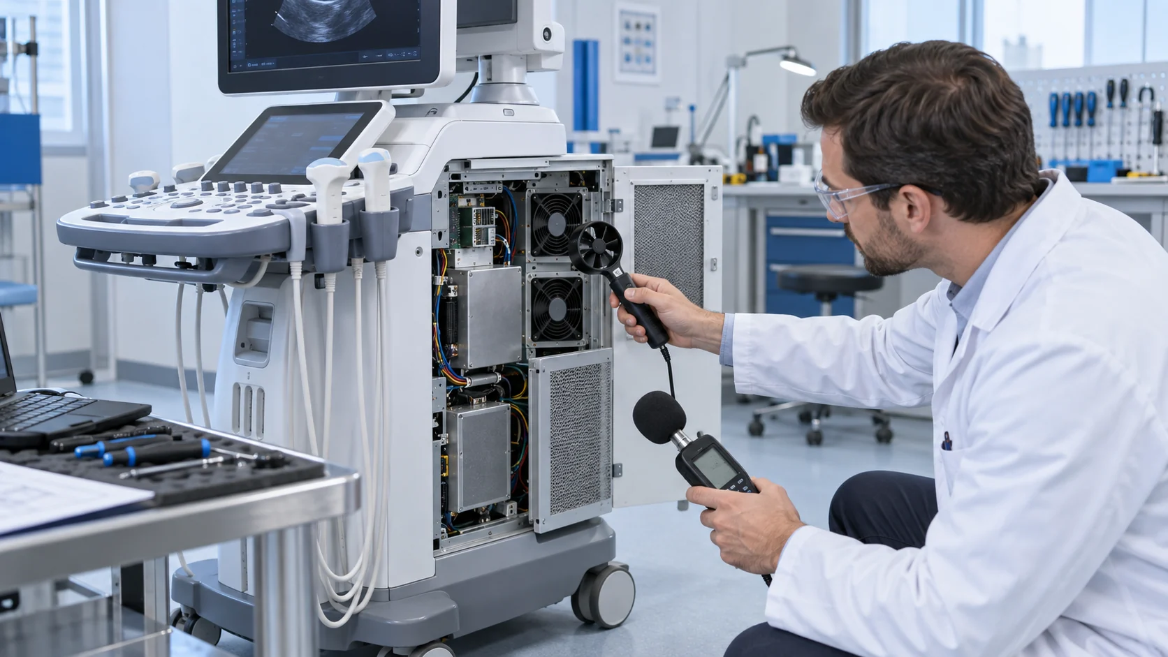
A fan may keep its commanded RPM while the filter pressure rises. It may also produce a good outlet temperature while a cable opening lets air bypass the power supply. Use smoke, tufts or a calibrated airflow measurement to locate the path, then repeat with the final gasket and grille. The animation is a qualitative explanation, not a CFD result or a product rating.

Noise Is a System Result, Not Only a Fan Datasheet Number
Medical users often notice a narrow tonal peak or speed hunting even when average sound pressure looks acceptable.
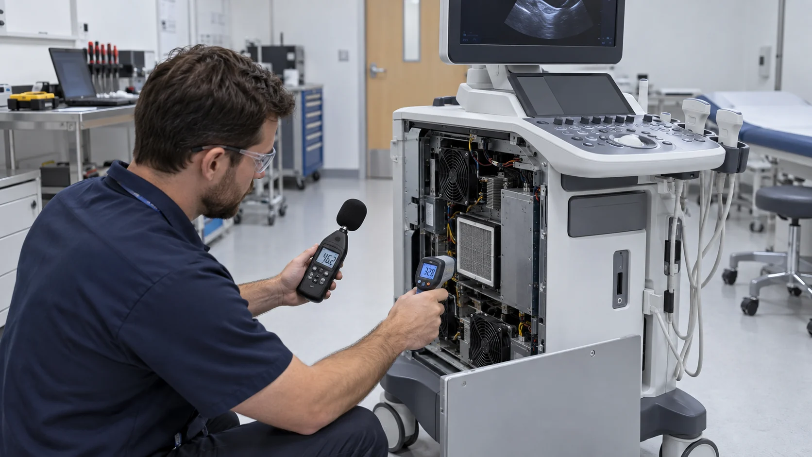
Measure sound pressure at the realistic operator and patient positions with the console assembled. Record the fan operating point, PWM command, voltage and the workload at the same time. A value measured in an open anechoic setup cannot be transferred directly to a console with a grille, panel cavity, filter and reflective room surfaces.
Listen for blade-pass tones, motor commutation, bearing roughness, panel buzz and speed hunting. A larger fan at a lower speed may reduce tonal content, but it can increase the panel opening and filter area. A blower may package better around a turn, but its outlet and scroll can create a different sound signature. Mechanical isolation and panel stiffness can be as important as changing the motor.
The target should be written as a pass/fail condition at a defined point, such as sound pressure at the operator location during normal imaging and maximum processing. If the equipment is used in a hospital, also consider the communication environment and local facility requirements. OSHA's workplace noise guidance is not a medical-device acceptance standard, but it illustrates why engineering controls and source reduction matter when people work near equipment for long periods.
Do not hide the acoustic result behind a single maximum value. Record one-third-octave or narrow-band data when a tonal complaint is possible, and note the fan speed that produced it. Check the console on a hard floor, beside a wall and in the intended room because panel reflections can change the perceived result. If a speed sweep shows a resonance, change the operating region, add isolation, stiffen the panel or revise the fan and grille combination. The quietest result is often a system decision rather than a motor-only decision.
Cleanability, Filter Loading and Service Access
A medical-console cooling path must survive routine cleaning and maintenance without creating a new contamination or reliability problem.
Define which surfaces are wiped, which components are removed and which openings may be exposed during service. A fan supplier should know whether the fan is inside a protected electronics compartment, behind a replaceable filter or directly exposed to the cleaning environment. Do not describe a fan as cleanable merely because its frame is accessible; define the approved cleaning method and verify that it does not damage the connector, bearing or insulation system.
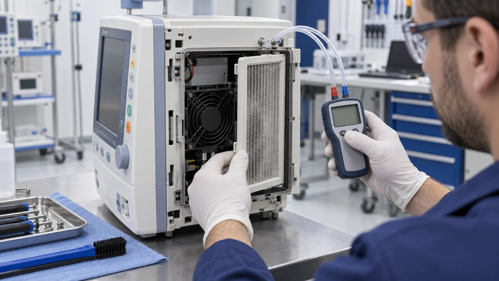
Filter loading must be tied to a service threshold. Record clean pressure, pressure at the change limit and pressure after replacement. A pressure switch can provide a useful maintenance signal, while FG/RD confirms the rotor state. Temperature should remain a second line of evidence because a partially blocked filter can still pass a fan RPM check while the heat source loses airflow.
Service access is also part of the design. The technician should be able to replace the filter or fan without disturbing patient-side wiring, probe connectors or safety barriers. Record screw torque, gasket compression, connector retention and the fan orientation after every service cycle. A replacement fan that fits the outline but changes the connector position can create an installation error even when its catalogue airflow looks similar.
Add a post-service verification step to the maintenance work instruction. After the filter or fan is replaced, confirm airflow direction, connector latch, gasket compression, fan feedback, differential pressure and the local heat-sink temperature during a short representative workload. A console that passes a visual inspection can still have a reversed fan, a pinched gasket or a partially seated connector. The check should be repeatable by a trained service technician and recorded with the device maintenance history.
Fan Fault Detection and Recovery Must Be Tested at the Device Level
FG and RD are useful signals, but they do not define the console's safe response by themselves.
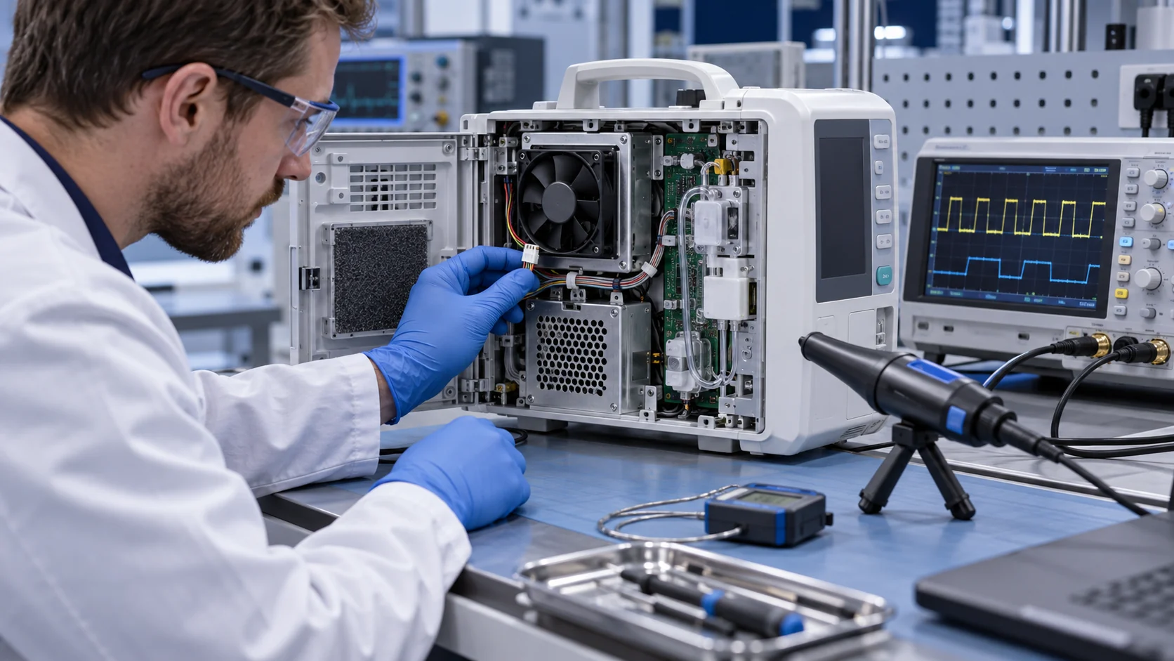
Test fan disconnected, locked rotor, intermittent connector, missing FG, active RD, blocked filter and temperature-sensor failure. Record detection time, alarm presentation, imaging response, data preservation, controlled shutdown and recovery after the fault is cleared. Test both a cold start and a warm restart because a fan can start successfully in one state and fail in another.
If PWM is used, validate the minimum duty, startup boost, ramp rate and control frequency with the final fan. A low command may be quiet but below the fan's stable operating region. A sudden full-speed command may create an acoustic complaint or a current transient. If the console uses a temperature curve, add hysteresis so the fan does not repeatedly cross a threshold during normal workload changes.
The fan's feedback proves an electrical or rotational condition. It does not prove that the filter is installed, the air path is sealed or the heat sink is receiving useful flow. The final device test must therefore combine feedback, pressure, temperature and functional response.
Test power interruption and recovery as well. Some consoles restart the fan from a low-voltage auxiliary rail before the main processor is ready; others restart with a high initial heat load. Verify that the fan reaches valid feedback within the device's allowed time, that a transient FG gap is not treated as a permanent failure, and that a real locked rotor is not hidden by a software retry loop. Record the response at minimum supply voltage and at the highest permitted ambient, where startup margin is often smallest.
An Anonymous Customer Scenario: A Quiet Console With a Service-Mode Hotspot
A European diagnostic-equipment developer found that its console passed the open-panel thermal test but ran hot after repeated filter service and quiet-mode changes.
The prototype used two compact axial fans behind a removable filter. With the panel open, the processor and power supply remained within the expected range. Once the panel and gasket were installed, the filter pressure increased and a cable bundle redirected part of the flow around the power supply. The console was quiet at minimum PWM, but the power-stage heat sink rose during an extended imaging session.
MEGA Tech reviewed the enclosure opening, filter resistance, fan command, FG wiring, gasket compression and sensor locations. The team compared a higher-static-pressure axial sample with a compact blower and measured both at the installed pressure. A revised baffle and connector position directed more air through the power-stage heat sink without putting the fan in the patient-side air path.
The customer repeated normal imaging, maximum processing, loaded-filter and fan-fault tests with the final service panel installed. The release record included acoustics at the operator position, filter pressure, local heat-sink temperature, fan feedback and alarm recovery. The important result was a repeatable device-level test, not a claim that one fan was universally quieter or safer.
This is an anonymized engineering scenario, not a public customer performance claim. The transferable lesson is to validate service configuration and fault behavior as part of cooling, rather than leaving them to field maintenance.
| Test | Measurements | Decision |
|---|---|---|
| Normal imaging | workload, fan command, local temperatures and sound pressure | confirm steady performance |
| Maximum processing | heat-sink slope, recovery and acoustic spectrum | confirm peak margin and tonal acceptance |
| Service state | filter pressure, gasket condition and airflow | confirm repeatable maintenance assembly |
| Fan fault | FG/RD, alarm timing and functional response | confirm controlled safe behavior |
| Cleaning cycle | connector, frame, gasket and insulation condition | confirm service compatibility |
How MEGA Tech Supports Medical-Equipment Cooling Projects
We help medical-equipment OEMs move from a quiet prototype to a validated production fan without treating the component as an isolated catalogue item.
MEGA Tech develops custom DC axial fans and compact centrifugal blowers for diagnostic consoles, imaging equipment, monitors, laboratory instruments and other electronics that need controlled airflow. We review the installed P-Q point, filter pressure, acoustic target, fan orientation, PWM or voltage control, FG/RD feedback, connector, startup, bearing choice, vibration, environment, service access and quantity.
For a first review, provide heat loss by operating state, airflow and static pressure at that airflow, maximum ambient, filter data, enclosure opening, voltage tolerance, control interface, feedback requirement, noise measurement position, cleaning exposure, life assumption, quantity and the final service sequence. If replacing an existing fan, send the part number and measured installed conditions. Same frame size does not automatically mean equivalent cooling or acoustic behavior.
We can also evaluate cost-competitive replacement fans for Sanyo Denki, SUNON, Delta, NMB and ebm-papst when the replacement is verified at the same pressure, voltage, mounting, feedback and environmental condition. We do not supply the medical controller, power supply, clinical function, cleaning protocol or regulatory approval. We support fan selection, customization, samples and air-path validation so the device team can make its own documented release decision.
Engineer FAQ: Medical Console Fan Selection
Short answers for a design review before the fan and service panel are frozen.
Q: Does IEC 60601-1 specify the exact fan? A: No. It addresses general basic safety and essential performance. The device manufacturer must define and verify the cooling-related performance and risk controls.
Q: Is free-air CFM enough? A: No. Measure the installed pressure, filter condition, local temperature and useful airflow through the heat source.
Q: Can FG prove cooling? A: No. FG indicates rotation or pulses. It does not prove the filter is open, the duct is sealed or the heat sink receives flow.
Q: Should a medical fan be cleaned in place? A: Only according to the device's approved cleaning procedure. Define exposure and verify the frame, bearing, connector and insulation condition.
Q: What information should we send for a custom sample? A: Heat load, airflow and static pressure at that airflow, voltage, control, feedback, envelope, filter pressure, noise target, environment, service method and quantity.
Questions for the Design Review
Use this checklist before releasing a medical-console fan or approving a replacement.
- What cooling loss would cause unacceptable performance degradation or a safety-related response?
- Which imaging workload produces the highest repeatable heat load?
- Have clean, loaded-filter and final-service-panel states been tested?
- Is the acoustic result measured at the operator position with the final enclosure assembled?
- Can a fan fault, blocked filter or missing FG be detected and handled as defined?
- Are the sensor locations near the actual limiting component and outside a misleading fan jet?
- Has the fan interface been checked at minimum voltage, minimum duty and warm restart?
- What exact P-Q, filter, noise, service and environmental information will be sent for the sample?