A Fan Fault Is a Medical-System Event
A stopped rotor is easy to name. The engineering work is proving when the device detects the loss, how it protects essential performance and what the operator sees next.
Medical equipment may depend on a cooling fan to keep a processor, power stage, sensor, lamp, imaging module or battery compartment inside its declared operating range. The fan can fail electrically, mechanically or through its installed airflow path. A disconnected tach wire may look like a rotor failure; a blocked grille may leave the RPM normal while the load temperature rises. The device therefore needs a defined response to loss of cooling, not only a fan part number.
For design review, separate four questions: what failed, what signal detects it, how fast the protected load becomes unsafe, and what the device does while the user is being informed. That logic is relevant to patient monitors, laboratory analyzers, infusion equipment, imaging accessories and medical power electronics. It also helps purchasers compare a candidate fan on more than nominal airflow and price.
This article presents a practical fan-failure and alarm-validation method. It is not a medical certification claim or a substitute for the applicable particular standard and risk-management file. The device manufacturer owns the essential-performance definition and final release decision.
Define the Cooling Failure Modes Before Choosing the Alarm
The alarm can only be useful if the risk analysis distinguishes a stopped fan from a restricted path or a misleading feedback signal.
Start with a failure-mode table. A rotor may stop because of loss of supply, locked rotor, bearing wear or control failure. The fan may rotate but deliver too little air because of a loaded filter, grille restriction, wrong direction or an installation gap. FG or tach feedback may be missing because the signal wire is open, while the fan is still spinning. A temperature sensor may drift or be placed in a region that stays cool while another component overheats.
For each mode, record the immediate indication, the protected function, the time available before the declared limit, and the risk control. A fan alarm may be a high-priority visual or audible indication, a controlled speed increase, a safe derating mode, a stop command or a service lockout. The correct response depends on the intended use and the device risk analysis; a generic ‘fan failure’ output is not enough.
A planning example: if a power board has 90 seconds of thermal margin after airflow stops, an alarm that arrives after 120 seconds cannot be the primary control. If the fan feedback is sampled every 5 seconds, the design team must include detection latency, filtering and the time required for the load sensor to cross its threshold. These values are illustrative test-planning numbers, not universal limits.
| Mode | What the fan signal may show | Evidence to validate |
|---|---|---|
| Supply or driver loss | RPM falls or disappears | voltage, current, RPM, alarm latency and restart |
| Locked rotor | zero RPM, high current or driver limit | locked-rotor protection and thermal response |
| Loaded path | RPM may remain normal | installed pressure/airflow and protected temperature |
| Feedback wire open | fan may still spin | signal fault detection and correct alarm state |
| Wrong direction or bypass | RPM normal | airflow direction, local temperature and fixture inspection |
RPM, FG and RD Are Useful but Not Equivalent
Feedback signals describe motor behavior; they do not automatically prove useful airflow or essential-performance margin.
FG or tach feedback can confirm that the rotor is turning. RD or locked-rotor output can identify a motor or driver condition. PWM command can show what the controller requested. None of these alone measures the air reaching the protected component. When resistance changes, a fan may keep a similar RPM while its operating point moves to lower airflow. A signal line can also remain electrically valid while the fan is installed backwards or the air is bypassing the heat sink.
Use a layered signal strategy. The first layer is fan-side feedback: supply voltage, command, RPM, current and alarm output. The second layer is installed-path evidence: differential pressure, airflow proxy or a validated temperature response. The third layer is device behavior: protected component temperature, derating, shutdown, recovery and operator indication. The layers should be correlated during normal operation and each declared fault state.
If the device uses only a tachometer, document the limitation. If a thermal sensor is used as a backup, verify its location, response time and failure behavior. If two fans are used in parallel, test one fan stopped and the reverse-flow pressure imposed on the idle fan. Redundancy without a tested installed response is an assumption, not evidence.
Measure Alarm Detection and Thermal Response Separately
A fast alarm is not automatically a fast thermal control, and a temperature rise is not automatically a valid fan alarm.
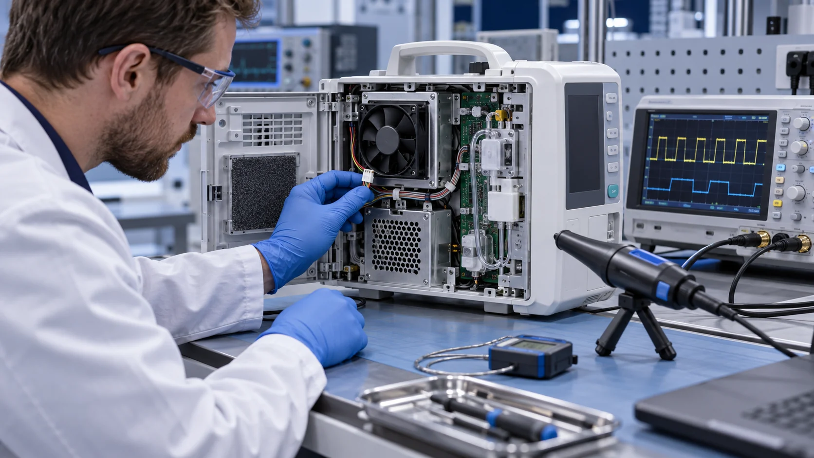
Create a time sequence for each fault: fault injection, signal change, controller decision, alarm output, operator indication, derating or shutdown, and recovery. Record the timestamps with a synchronized data logger. This separates sensor delay from software filtering and from the actual thermal response of the load. A device may detect a missing FG pulse in milliseconds but need much longer to detect a restricted airflow through temperature.
Test the normal state first. Establish the fan command, RPM, current, pressure or airflow proxy, inlet temperature, protected temperature, alarm state and acoustic condition. Then inject one fault at a time. Disconnect the fan supply, open the feedback line, apply a controlled path restriction, stop one fan in a redundant pair and introduce the declared sensor fault. Do not combine faults until the single-fault behavior is understood.
The acceptance report should state the threshold, delay, hysteresis, debounce time, priority, latching behavior, reset condition and operator message. If the alarm is intended to protect essential performance, show the measured time between fault injection and the protective action. IEC 60601-1-8 is a recognized alarm-system reference, but its application must be interpreted with the device's intended use and particular standards.

Test the Installed Path, Not Only an Open Bench
A fan can pass a free-air test and still fail to protect the device when the grille, filter and heat sink are installed.
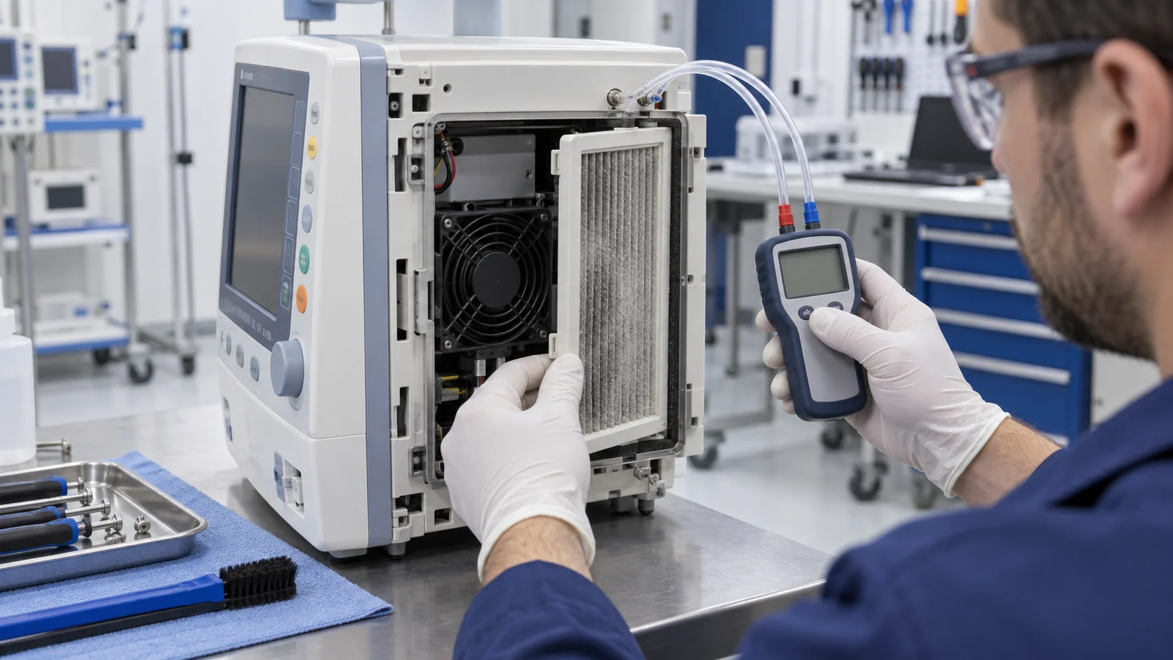
Build the test fixture around the real restriction. Include the grille free area, filter or acoustic mesh, gasket, cable openings, heat sink, shroud, duct length and exhaust condition. Mark the pressure-tap planes. A fan supplier's maximum airflow is a zero-pressure point; it does not tell the team what happens at the installed operating point. Use the fan P-Q curve and the system resistance together, then confirm the result in the device or a correlation fixture.
For a planning example, assume a compact analyzer needs 16 CFM at 5 mmH2O. A clean bench result at 30 CFM may look comfortable, but if the installed path reaches 8 mmH2O the actual airflow can be much lower. Now stop one fan or open a feedback wire and repeat the test. The alarm may work while the remaining fan is pushed into a noisy or unstable region. The values are illustrative and should be replaced with measured device data.
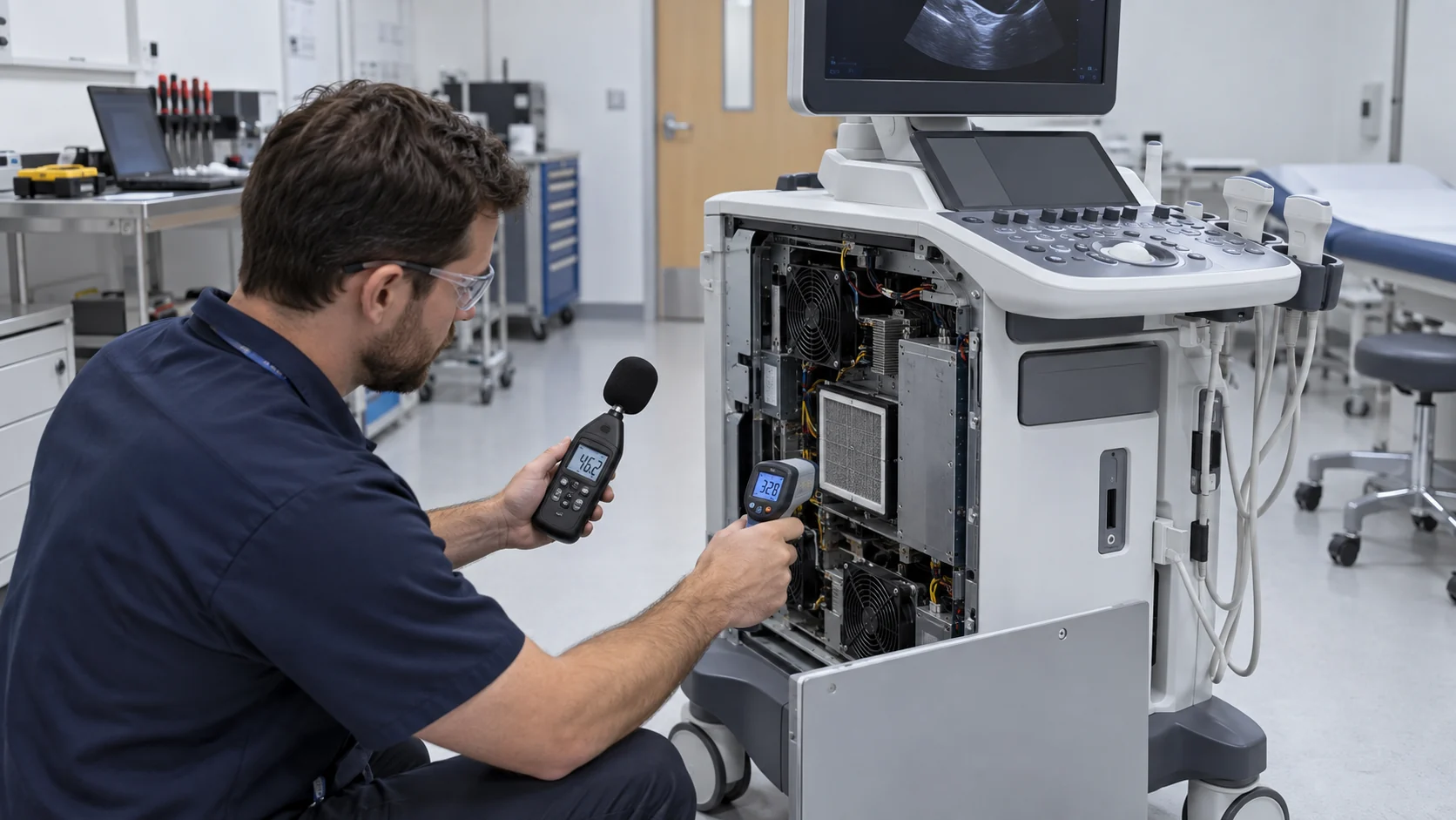
Check local temperatures, not only outlet air. A normal average exhaust temperature can hide a hot processor, connector or regulator behind a blocked branch. A thermal camera, multiple thermocouples or a validated sensor array can show whether the alarm threshold is early enough for the protected function.
| Layer | Record | Release question |
|---|---|---|
| Fan | voltage, command, RPM, current, FG/RD | does the interface detect the declared fan fault? |
| Air path | pressure, airflow proxy, direction and restriction | does the installed fan move useful air? |
| Load | component temperatures and operating mode | does the protected function keep margin? |
| Alarm | latency, priority, latch, reset and message | can the operator respond correctly? |
| Recovery | restart, alarm reset and temperature return | does the device return to a validated state? |
Redundancy and Derating Need Their Own Test
Two fans do not automatically provide safe redundancy; the idle path, controller logic and remaining fan duty can change the result.
For a dual-fan assembly, test normal operation, one fan stopped, one fan disconnected, one feedback line open and the restart of the failed fan. Measure reverse flow through the idle fan and the pressure seen by the operating fan. In a compact enclosure, the stopped fan can become a restriction or a bypass route. The remaining fan may need a higher command, which changes noise, current and bearing duty.
Derating can be a valid risk control when it is defined before the fault. Specify the load power, fan command, protected temperature, time limit, operator indication and recovery. Do not call a device safe merely because the temperature eventually stabilizes; the clinical function may already be degraded. Conversely, do not choose a shutdown threshold without understanding the stored thermal energy and the time required to place the equipment in a safe state.
A practical acceptance matrix has at least normal, one fan stopped, feedback open, restricted path and recovery states. If the device uses a watchdog or service timer, test power interruption and warm restart as well. Redundancy reduces risk only when the complete hardware and software response is repeatable.
Representative Medical Equipment Alarm Review
An anonymous development example shows why a replacement fan must be tested with the alarm interface and the installed load.
Consider a compact diagnostic module using one DC axial fan to cool a processor board and a regulated power stage. The original design monitored FG pulses. During a service review, the team found that the fan could report a plausible speed while a partially blocked inlet reduced the airflow to the power stage. The software alarm responded to a stopped rotor, but not to the installed restriction.
The review added a pressure-tap point, two protected temperature points and a controlled inlet restriction. The candidate sample was checked at normal command, minimum command and a declared high-temperature state. The team then opened the FG line, stopped the fan, restricted the inlet and restored the path. The result was a clearer separation between rotor fault, path fault and device thermal response.
The sample was not accepted because it had a higher free-air number. It was accepted only after the connector, PWM response, FG behavior, current, acoustic condition, thermal margin and alarm sequence were compatible with the actual equipment. This is an illustrative engineering scenario, not a named customer result, a certification statement or a universal alarm threshold.
How MEGA Tech Supports Medical Fan Alarm Validation
MEGA Tech helps develop the fan-side sample and interface while the device maker owns alarm design, risk management and compliance.
MEGA Tech develops custom DC axial fans and compact centrifugal blowers for medical and laboratory equipment. We can review frame and thickness, mounting, airflow direction, connector and cable, PWM or voltage control, FG or RD feedback, bearing configuration, startup behavior, current, noise and the installed pressure/airflow duty. Samples can be matched to the customer's enclosure rather than selected from a free-air headline.
For a useful review, provide airflow and static pressure at that airflow, inlet temperature and altitude basis, voltage tolerance, control interface, connector, envelope, noise target, life assumption, duty cycle, grille or filter details, alarm logic, protected load temperature and the required fault states. If the current fan is a Sanyo Denki, SUNON, Delta, NMB or ebm-papst part, include its working point and interface details rather than relying only on the part number.
We can support a small first build and fan-side measurements for the declared states. We do not supply medical controllers, alarm software, cabinet safety design, emergency ventilation, medical certification or clinical approval. The device manufacturer owns the essential-performance definition, alarm priority, risk controls, maintenance procedure and final release.
Engineer FAQ: Medical Fan Failure and Alarms
Use these questions before approving a fan interface, alarm threshold or redundancy claim.
Q: Does a missing FG pulse prove that the equipment has lost cooling? A: It proves a feedback condition. Validate the fan, wiring, installed airflow and protected load separately.
Q: Can a normal RPM signal prove a loaded grille is safe? A: No. A restriction can move the operating point while RPM remains within the expected window.
Q: Should a fan alarm always shut the medical device down? A: Not necessarily. The response depends on intended use, essential performance, thermal time margin and risk controls defined by the device manufacturer.
Q: What is the minimum single-fault test? A: Define the relevant fault, inject it, measure detection and alarm latency, verify the protective action, and document recovery or safe shutdown.
Q: Is N+1 redundancy valid if the fan is physically duplicated? A: Only after testing the idle fan's reverse-flow restriction, remaining-fan duty, alarm logic and actual protected temperatures.
Q: What can MEGA Tech customize? A: Frame, thickness, airflow direction, connector, cable, PWM, FG or RD, bearing, pressure/airflow duty and mounting can be reviewed around the actual equipment requirement.
Questions for a Medical Cooling-Fault Design Review
A short checklist helps turn a fan alarm claim into objective evidence.
- Which clinical or equipment function is protected by the cooling system?
- What are the normal and single-fault performance limits?
- Which failure modes are detected by RPM, FG, RD, current, pressure or temperature?
- What is the measured time from fault injection to alarm and protective action?
- What happens when the feedback wire fails while the fan still rotates?
- What happens when the inlet is restricted while the fan reports normal RPM?
- Does one stopped fan create reverse flow or excessive duty on the remaining fan?
- What are the alarm priority, latch, reset, operator message and service record requirements?
- What are the voltage, PWM, FG/RD, startup, minimum-speed, noise and current limits?
- Has the candidate sample been tested with the actual enclosure, grille, load and recovery procedure?