A Medical Fan Is Part of the Safety Evidence Chain
In medical equipment, a fan is not approved because it spins and moves a catalogue airflow. It is accepted when the installed cooling path supports the device's basic safety and essential performance throughout the intended service life.
Medical equipment can contain processors, power supplies, imaging electronics, pumps, displays, sensors and high-voltage conversion stages in a compact enclosure. The cooling fan, filter, grille, heat sink, duct, cable routing and control logic determine whether those components remain within their approved conditions. Noise can affect the user environment, vibration can affect sensors, and electromagnetic disturbances can change the behavior of the fan controller or the equipment around it.
The engineering mistake is to let procurement replace a fan using only frame size, voltage and maximum CFM. A replacement can fit mechanically while changing pressure-flow behavior, startup current, tach pulses, PWM minimum duty, conducted noise, acoustic tone or failure detection. Those changes may not appear in a short room-temperature bench test.
This guide presents a validation workflow for medical-device OEMs and thermal engineers. It does not assign medical certification, clinical safety or regulatory approval to the fan supplier. The responsible medical-equipment manufacturer owns the risk analysis, essential-performance definition, EMC test plan and production equivalence argument.
Define Essential Performance Before Choosing the Fan
A thermal target becomes meaningful only after the team states what must continue working, under which operating and fault conditions.
For a patient monitor, the display, processor and alarm functions may need to remain available. For imaging equipment, the thermal limit may relate to detector stability, image quality, scan availability or a controlled shutdown. For a medical warmer or airflow device, temperature, pressure and alarm response may be directly related to patient safety. The cooling fan is not the clinical function, but fan failure can affect the function that the risk analysis identifies as essential.
Write the thermal requirement in measurable terms: component temperature, enclosure temperature, allowable drift, time to alarm, time to controlled derating, recovery after a fan replacement and acceptable behavior after a single fan fault. Avoid a vague requirement such as 'keep the electronics cool'. Name the sensor, measurement point, load state and ambient condition.
For an illustrative calculation, suppose an electronics bay dissipates 60 W and the design allows a 10 K air rise. Using Qv = P/(rho x cp x deltaT), with air density about 1.2 kg/m3 and heat capacity about 1.0 kJ/(kg K), the ideal airflow is about 0.005 m3/s, or 10.6 CFM. The actual fan selection must still account for filter, heat sink, grille, duct, leakage and the temperature limit of the critical component.
| Input | Why it matters | Record |
|---|---|---|
| Critical function | Defines what the cooling fault must not compromise | risk analysis and essential-performance statement |
| Heat load by mode | Thermal loss changes between standby, scan and service modes | power and duty log |
| Temperature points | Average air can hide a local device hotspot | named sensor and calibration |
| Fault response | A fan alarm must lead to a defined action | alarm, derating and shutdown logic |
| Service life | Fan, filter and dust condition change with time | maintenance and replacement plan |
Select at the Installed Working Point, Not Free-Air CFM
Filters, heat sinks and protective openings turn the enclosure into a system curve that must intersect the fan curve at the required airflow.
Medical devices often use compact air paths because enclosure size, cleanability, patient proximity and acoustic requirements limit the available space. A small grille or fine filter can add meaningful pressure. A heat sink with narrow fins may need more static pressure than a simple cabinet exhaust path. If the fan is selected only from maximum airflow at zero pressure, the actual working point can be far below the thermal requirement.
Use a pressure budget with named elements. For example, a filter may contribute 45 Pa, a grille 20 Pa, a heat sink 70 Pa, a duct transition 25 Pa and an outlet 15 Pa at the target flow. The installed fan therefore needs to deliver that flow at about 175 Pa, before an agreed design margin. The numbers are an example; the medical equipment team should measure or calculate its own path.
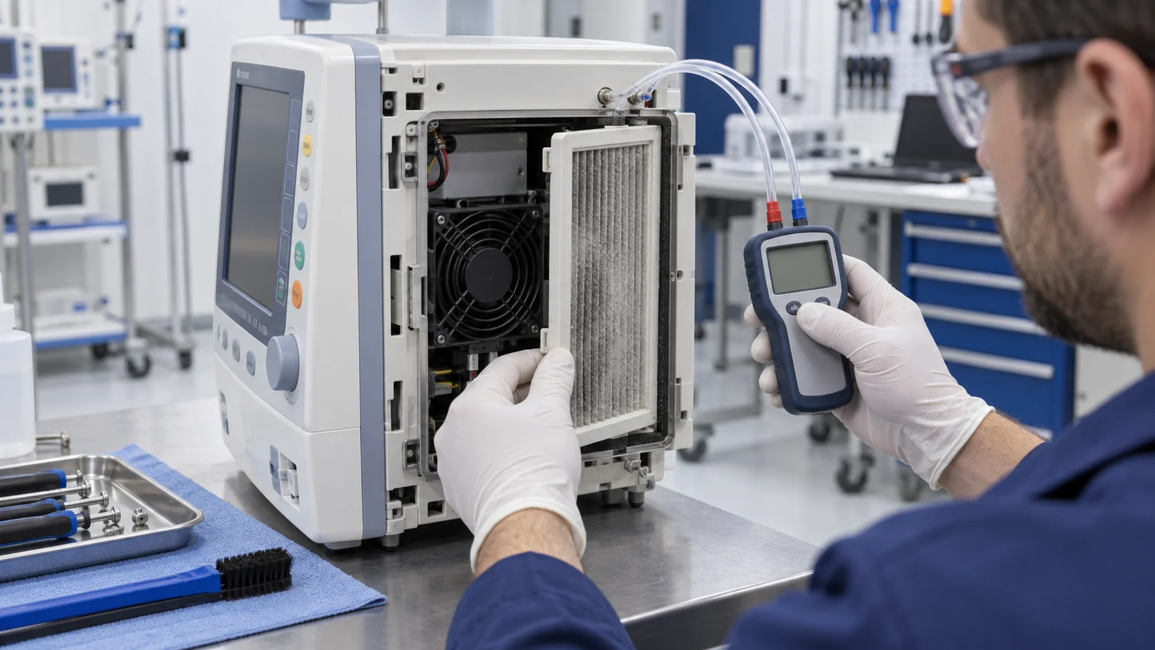
A replacement fan should be compared at the original fan's operating point and control state. Record airflow or a calibrated proxy, static pressure, voltage, current, PWM or voltage command, FG/tach behavior and the critical temperature. A normal RPM signal proves rotor movement, not that the filter, heat sink and device receive the intended air.
Interactive: See the Fault, Temperature Rise and Alarm Response
The animation shows why the controller needs more than a binary fan-running signal.
A fault can occur in several ways: rotor stops, speed falls below the expected range, filter loads, an outlet is blocked, the fan loses power, the feedback wire is open, or the controller commands a duty that is too low to start the motor. These conditions do not produce identical temperature curves. The alarm logic should identify what it can, and the thermal response should be tested when it cannot.
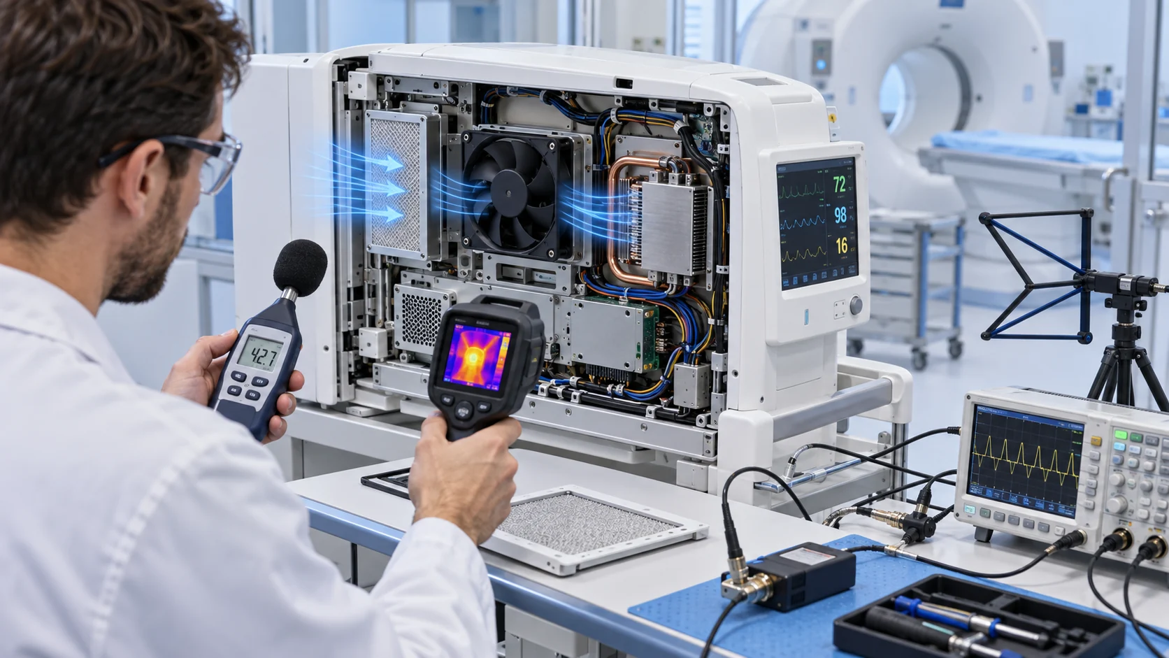
The test should record fan command, voltage, current, FG or tach, RD or lock status where available, pressure or airflow proxy, critical temperatures and alarm timestamps. Introduce the fault after the equipment reaches the representative load and temperature. A cold-start fault test is not enough if the real risk occurs after a long scan or treatment cycle.
Use the animation to structure the test plan, not to assign a universal time-to-alarm. The allowable response depends on component thermal mass, sensor location, essential performance, operator workflow and the medical device risk controls.

Acoustic Validation Must Include the Installed Enclosure
A fan's published dB-A value cannot predict every medical-device noise result because the duct, grille, panel and mounting can create tones and structure-borne vibration.
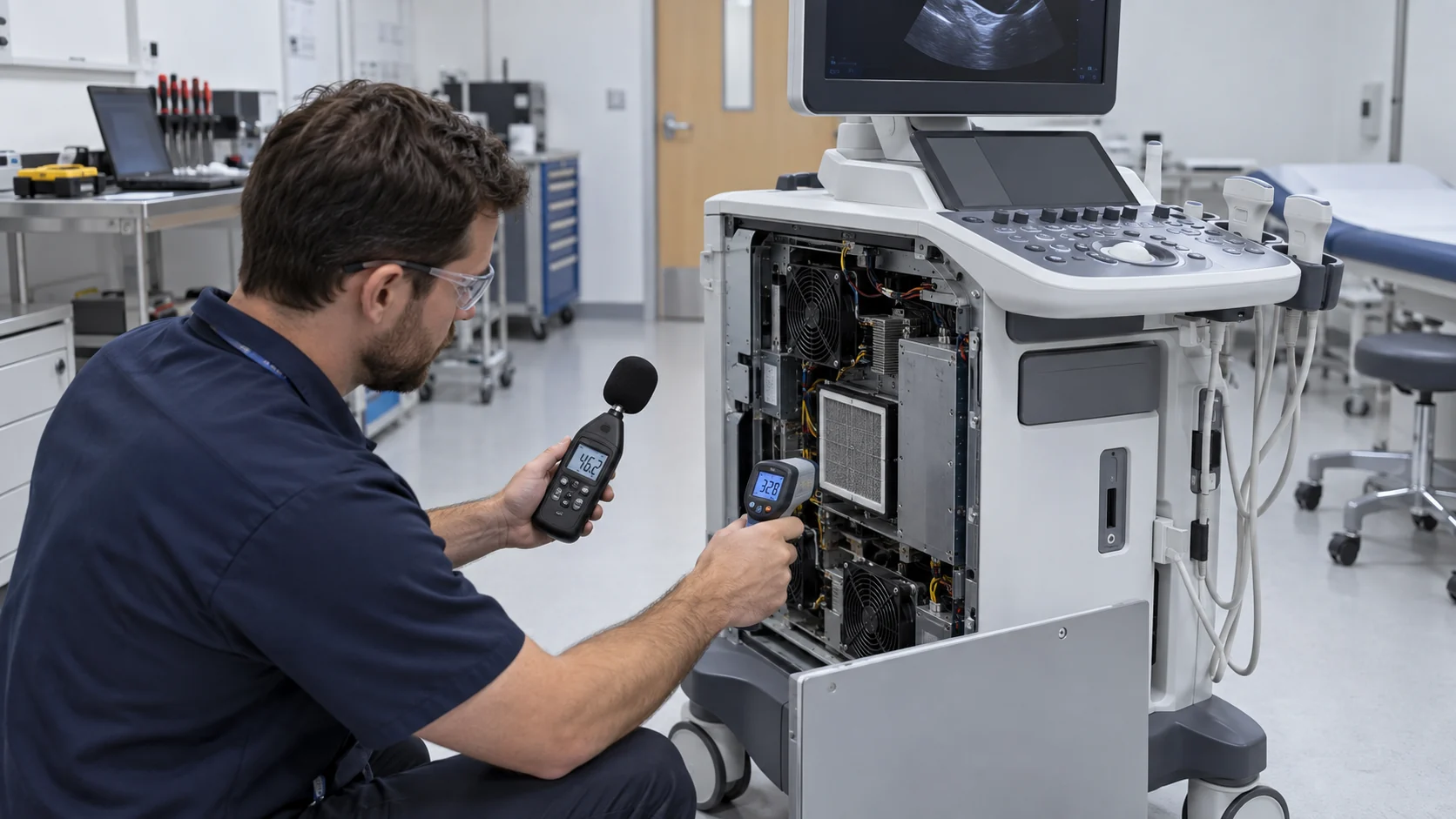
Medical environments are sensitive to continuous noise, tonal peaks and sudden changes. A fan that sounds acceptable in a free-air fixture can excite a panel, grille or duct once installed. The measurement point also matters: an operator standing beside the device hears a different spectrum from a microphone placed one metre in an open lab.
Use a comparable method and record the fan operating point. Standards such as ECMA-275 provide a framework for measuring airborne noise and structure-borne vibration of small air-moving devices as a function of airflow and static pressure, but the medical equipment maker must still assess the complete installed product and its intended environment.
Separate broadband airflow noise, blade-passing tone, motor commutation, bearing noise and structure-borne vibration where practical. Then compare the acoustic result with temperature, pressure and fan command. Reducing RPM may reduce noise while sacrificing thermal margin; a better duct, mounting isolation or fan blade choice may provide a more stable solution.
- Measure at the defined operator or patient-side location.
- Record airflow, pressure, RPM or PWM with the sound result.
- Check panel, grille and duct resonance at the dominant tones.
- Test standby, normal load, peak load and fault-recovery states.
- Do not trade away essential thermal performance to meet a sound number without risk review.
EMC and Fan Control Are an Integrated Test
A fan motor and its control electronics can be affected by, and can contribute to, electromagnetic disturbances in the medical system.
Medical EMC guidance treats ventilation, cooling and heating monitoring as part of the equipment's broader safety and essential-performance engineering. That does not mean every fan has a separate medical certification. It means the selected fan, controller, wiring, power converter, sensor and enclosure must behave acceptably as the integrated product under the disturbances defined by the risk and EMC test plan.
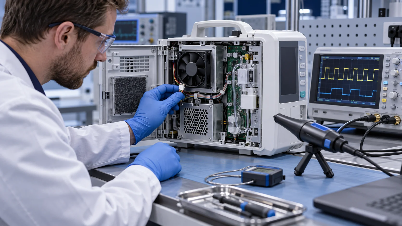
Check PWM edge behavior, power-rail ripple, current transients, FG/tach wiring, RD alarm lines, cable routing and grounding. A replacement fan with a different internal driver can change conducted noise or create a false tach reading even when its airflow is similar. Keep the fan harness separated from sensitive sensor and communication lines where the equipment design requires it.
During verification, monitor the essential function, fan command, fan feedback and critical temperature. During validation, use the final or production-equivalent configuration and the intended operating environment. The equipment manufacturer should define which deviations are acceptable and what constitutes a loss of essential performance.
Fault Detection Should Combine Feedback and Thermal Evidence
FG, tach and RD are useful signals, but they should be linked to the temperature response and the actual air path.
A fan can report a normal speed while a filter is blocked, a gasket is leaking, a duct is disconnected or air is bypassing the heat sink. Conversely, a tach pulse can disappear briefly during a control transition without the equipment losing meaningful thermal performance. The alarm logic should define persistence, hysteresis and the action for each condition.
A practical sequence may include a start check, a minimum-speed check, a feedback plausibility check, a temperature-rate check and a controlled response if the evidence disagrees. The exact thresholds belong to the device maker's risk analysis. The fan supplier should provide the electrical behavior needed to make those checks repeatable.
For example, if a fan command is high, FG is normal, pressure is low and the component temperature rises faster than expected, the likely fault is not a simple locked rotor. Investigate filter, duct, bypass, sensor position, heat-sink contact and recirculation. A controller that only displays 'fan OK' would miss that chain.
Validation Matrix: Standby, Normal Use, Worst Case and Recovery
The most useful medical fan report is a matrix that connects the fan state to the device function and the operator response.
Test the equipment in standby and normal operation first, then introduce the highest representative heat load. Include the filter and service configuration expected in the field, not only a clean prototype. If the unit has a patient-side acoustic requirement, measure it in the intended enclosure and room arrangement. If the fan is replaceable, repeat the critical tests with the production-equivalent replacement assembly.
A thermal soak matters because a short test can hide heat stored in the heat sink, transformer, battery or enclosure. Start the fault after the equipment reaches the defined state, record the time to alarm, temperature rise, essential-function response and recovery after the fan returns. Repeat at the voltage and ambient extremes that the design declares.
Separate measured data from estimates, vendor claims and risk-analysis limits. This makes the record usable for design changes, supplier substitutions and future service without implying that a component supplier owns the medical-device approval.
| State | Measurements | Acceptance question |
|---|---|---|
| Standby | fan command, noise, current, temperature | does the fan avoid unnecessary disturbance? |
| Normal operation | airflow, pressure, feedback and key temperatures | does the installed path maintain margin? |
| Peak duty | hotspot temperature, acoustic output and EMC behavior | does essential performance remain available? |
| Fan fault or restriction | alarm time, temperature slope and function response | does the defined safe response occur? |
| Recovery or replacement | restart, feedback, noise and thermal return | does the production-equivalent assembly recover predictably? |
Where MEGA Tech Fits In
We support the fan-side engineering and sample work while the medical-equipment manufacturer retains system safety and certification responsibility.
MEGA Tech can review custom DC axial fans, centrifugal blowers and fan modules for patient monitors, imaging equipment, laboratory equipment, medical cabinets, pumps and other electronics enclosures. The review can cover pressure-flow behavior, frame and thickness, PWM or voltage control, FG/RD feedback, connector and cable exit, bearing configuration, temperature, noise, vibration, filter condition and small-batch sample development.
For a first review, provide the equipment sample or section drawing, heat load by operating state, critical components and temperatures, filter and grille, target airflow at pressure, voltage tolerance, control and feedback definition, sound measurement point, EMC constraints, service interval and expected quantity. A thermal image of the failure state and the existing fan's part number help, but they do not replace the installed test.
We can also evaluate cost-competitive replacements for Sanyo Denki, SUNON, Delta, NMB or ebm-papst fans. The comparison should include airflow at pressure, acoustic behavior, startup, feedback, current, mounting, thermal response and production-equivalent validation rather than only a lower catalogue price.
Engineer FAQ: Medical Equipment Cooling Fans
These questions keep component selection separate from the medical device maker's safety and EMC responsibilities.
Q: Does a fan need its own IEC 60601 certification to be used in medical equipment? A: The equipment manufacturer's compliance strategy determines the applicable requirements. The fan supplier provides component evidence; the final medical equipment must be assessed as an integrated system.
Q: Can a normal RPM signal prove cooling performance? A: No. It proves rotor feedback. Pressure, airflow, filter state and component temperature are still required.
Q: Why validate noise at the installed point? A: The enclosure, grille, duct and mounting can create tonal or structure-borne noise that does not exist in a free-air test.
Q: Why include EMC in a fan replacement review? A: A different motor driver or cable arrangement can change conducted emissions, immunity behavior, tach integrity or controller response.
Q: What should happen when a fan fails? A: The risk analysis and essential-performance definition should specify alarm, derating, controlled shutdown or continued operation. The test should measure the actual time and temperature response.
Q: Can MEGA Tech make small samples for a new medical device? A: Yes. We can review the customer sample, adjust fan and interface parameters, build samples and provide fan-side test evidence for the responsible OEM validation process.
Medical Cooling-Fan Review Checklist
Use this list before approving a new fan or releasing a replacement into a medical product.
- What is the essential function affected by loss of cooling?
- Which component and sensor point define the thermal limit?
- What airflow is required at the actual filter, heat sink and grille pressure?
- Were noise and vibration measured in the final enclosure and user position?
- Were PWM, FG/RD, current, voltage and startup behavior checked?
- What EMC disturbances and cable configurations belong in the integrated test?
- How quickly does the alarm respond after a fan stop or airflow restriction?
- Was the equipment thermally soaked before the fault was introduced?
- Can the replacement fan be shown production-equivalent to the validated sample?
- Which evidence belongs to the fan supplier and which belongs to the medical-device OEM?