A Fan Can Move Air and Still Leave a Condensation Risk
Humidity is not only an environmental specification. It changes the temperature margin, insulation condition and airflow path that a medical device must control.
Cooling fans in patient monitors, laboratory analyzers, imaging accessories, therapy equipment and medical power electronics are often evaluated in a clean, dry laboratory. That is necessary, but it is not the complete installed condition. A device may be stored in a cool room, moved into a warm clinical space, cleaned with a damp process or operated beside a humidifier. The enclosure can then contain air with a higher dew point than the coldest internal surface.
The practical failure is not always a visible pool of water. Moisture can appear as a thin film on a connector, a PCB edge, a sensor window, a heat sink or a fan frame. It can alter leakage, insulation resistance, corrosion rate, optical measurement and the reliability of a control signal. The fan may still report normal RPM. That is why a humidity review must connect the fan, vents, thermal mass, seals, sensors and restart sequence.
This article gives thermal engineers and medical-equipment purchasers a design-review method for condensation risk. The examples are illustrative planning values, not a certification result, a clinical claim or a universal environmental limit. The device manufacturer must define the applicable risk controls, cleaning procedure, essential performance and compliance test plan.
Use Dew Point, Not Relative Humidity Alone
Relative humidity changes with temperature. Dew point makes the risk boundary easier to compare with an actual surface temperature.
A useful first check is to calculate or measure dew point from air temperature and relative humidity. As an illustrative example, air at 25 °C and 70% RH has a dew point of roughly 19 °C. If a metal bracket, connector or heat sink inside the device is at or below that temperature, moisture risk exists whenever humid air reaches it. The exact value depends on the psychrometric method and measurement uncertainty, so use a validated instrument or calculation in the formal test report.
The opposite mistake is also common: an engineer sees 70% RH and assumes the same risk at every temperature. At 35 °C and 70% RH the dew point is much higher, near 29 °C. At 10 °C and 70% RH it is near 5 °C. The fan selection therefore cannot be separated from the inlet temperature range, cold soak, warm-up rate and the location of the coldest surface.
The fan changes this boundary indirectly. Higher airflow can reduce local hot spots, but it can also transport humid room air directly across a cold surface during warm restart. A low-flow pocket can leave one connector cold while the average enclosure temperature looks acceptable. Record inlet temperature, RH, dew point, fan command, RPM, pressure or airflow proxy, and the temperature of the suspected cold surfaces.
| Air state | Approx. dew point | Engineering question |
|---|---|---|
| 25 °C / 50% RH | about 14 °C | Can any internal surface stay at or below 14 °C during start-up? |
| 25 °C / 70% RH | about 19 °C | Does humid air reach a connector or heat sink below this boundary? |
| 35 °C / 70% RH | about 29 °C | Does the warm site raise condensation risk during a cold restart? |
| 10 °C / 70% RH | about 5 °C | What happens when the device moves from cold storage to a warmer room? |
Fan Placement Can Create or Remove a Cold Moisture Path
The same fan can behave differently when the inlet, exhaust, grille and cold components change position.
A fan that pulls air through a device can help keep the electronics uniform, but it may also pull humid air through a gap that was not part of the intended path. A fan that pushes air into an enclosure can pressurize the housing and reduce uncontrolled ingress, but it can also send a concentrated jet onto a cold wall or a small sensor cavity. Neither arrangement is automatically correct; the installed pressure, leakage and temperature map decide.
Check the inlet-to-load distance, the opening area, the grille free area, the gasket compression and the location of the first obstruction. In compact medical equipment, a decorative grille or acoustic mesh can add pressure drop while a cable opening creates a bypass path. The fan may reach its commanded speed while the coldest region receives little flow. Use smoke, tufts, thermal imaging or a validated local airflow method to understand the actual path, then confirm with temperature and dew-point measurements.
Avoid placing a temperature or humidity sensor only in the return air. Return air is a useful average, but it can miss a local cold surface behind a shield. A design review should identify the coldest credible component and the warmest humid air that can reach it. If the fan is variable-speed, test both minimum stable speed and the commanded speed after a warm restart; low speed can leave pockets that do not appear in a steady-state bench test.

Four Situations That Deserve a Humidity Test
Condensation risk often appears during transitions, not during the stable part of a factory thermal test.
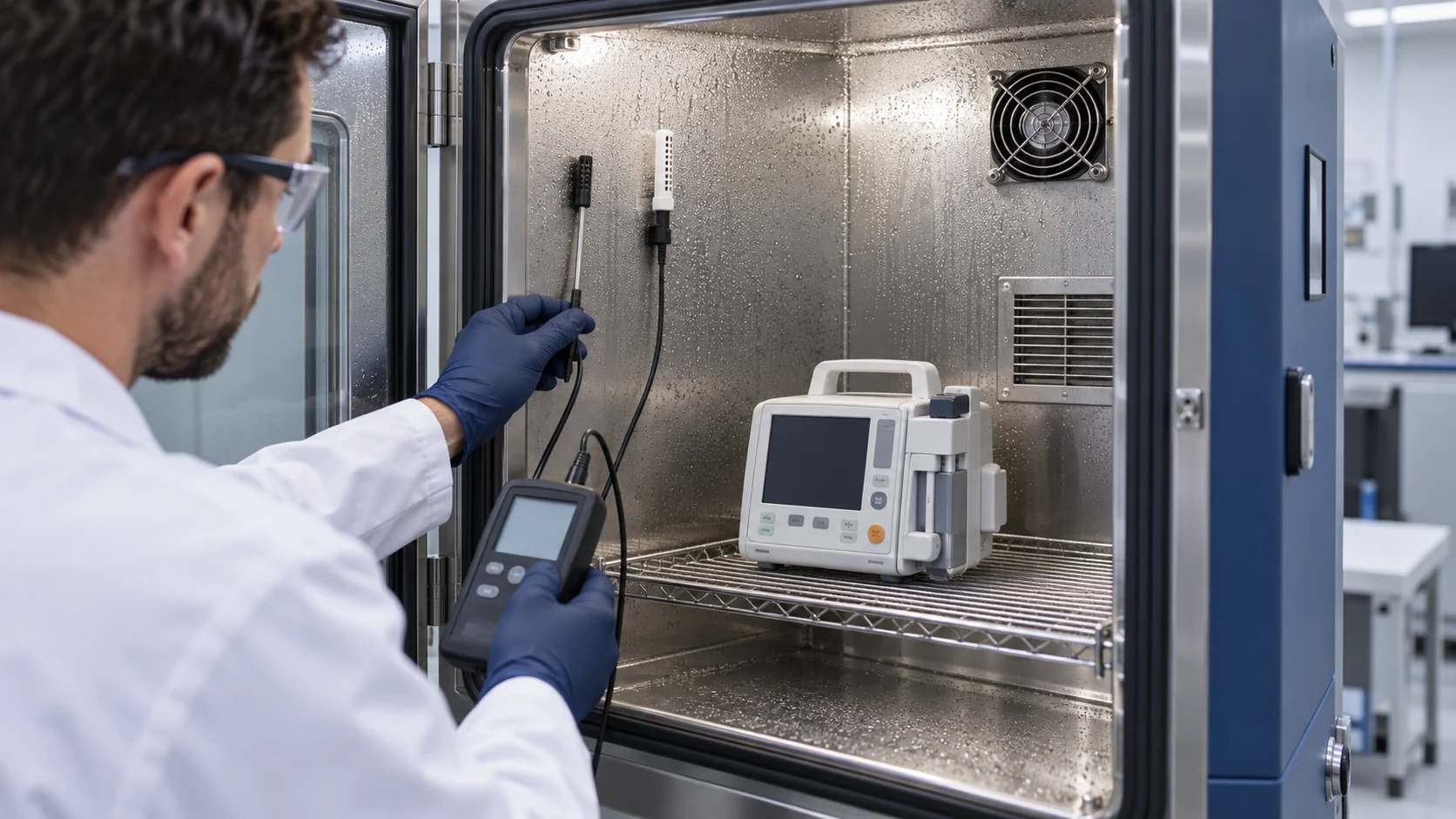
First, test cold storage followed by warm humid operation. A device can arrive with a cold internal mass while the surrounding air is already warm and moist. Starting the fan immediately may move that air across cold metal before the enclosure equilibrates. Define whether the device is allowed to operate immediately, requires a wait period or must control a warm-up sequence.
Second, test cleaning and drying. A wipe-down, spray, disinfection process or wet-room transfer can change local humidity and leave moisture near vents. The fan should not be treated as a dryer unless the complete device procedure proves that airflow, temperature and material compatibility make that safe. The medical device maker owns the approved cleaning and infection-control procedure; the fan supplier can only help characterize the airflow and environmental boundary.
Third, test standby and warm restart. A fan may stop during a low-power state while a heat sink remains cold or a humid path remains open. On restart, the fan changes pressure and air exchange abruptly. Record the time from power-on to stable temperature, fan command and any alarm or sensor transition. Fourth, test the highest credible site humidity and the lowest credible surface temperature together. A typical-room test is not a worst-case envelope.
| State | Record | Pass/fail decision |
|---|---|---|
| Cold-to-warm | storage temperature, room RH, dew point and delay | no unacceptable moisture or unsafe restart |
| Normal humid | inlet RH, surface temperatures, fan duty and load temperature | thermal and moisture margins remain inside the device limits |
| Cleaning / dry-out | procedure, exposure time, airflow, insulation and alarms | approved procedure restores the declared state |
| Standby / warm restart | fan start, command, RPM, pressure proxy and coldest point | no hidden low-flow or condensation event |
| High RH boundary | RH accuracy, dew point, cold surface and recovery | limit and recovery are documented, not assumed |
Do Not Use RPM as a Moisture or Cooling Certificate
A normal feedback signal can coexist with a blocked path, a cold pocket or a connector exposed to humid air.
FG or tach feedback is valuable because it confirms rotor movement and can detect a stopped fan. It does not directly measure air reaching the load, and it does not measure dew point margin. A fan can hold a similar RPM as resistance changes, while the operating point moves to lower airflow. Conversely, a higher command can increase airflow in one branch while sending a jet into a cold surface or increasing noise and vibration.
Use the signal set that matches the device risk analysis. A practical engineering record may include fan voltage, PWM or command, RPM, current, differential pressure, a calibrated airflow proxy, inlet temperature, RH, dew point, protected load temperature and the coldest surface temperature. The exact acceptance limits belong to the medical device design, not to a generic fan datasheet.
For a planning example, assume a compact analyzer needs 14 CFM at 4 mmH₂O during normal operation. If a grille, filter and sealing change raise the installed resistance toward 7 mmH₂O, the candidate must be checked on its P-Q curve at the new operating point. If the internal cold surface is simultaneously 18 °C and the room dew point is 19 °C, the thermal result alone is not enough to release the design. These are illustrative values to structure a test, not a universal pass limit.
Validate the Fan, Enclosure and Sensor as One System
The fan supplier can characterize the fan-side behavior; the medical device maker must validate the complete safety and performance boundary.
Start with the installed drawing: fan envelope, mounting, airflow direction, inlet and exhaust openings, gasket, cable route, heat sources, cold masses and sensor locations. Add the electrical interface and the control behavior at start, minimum speed, normal speed, fault and recovery. Then define the humidity boundary: storage, transport, operation, cleaning, standby and warm restart. This prevents an environmental test from becoming a vague ‘high humidity’ label with no repeatable state.
For each state, record the same core data. The fan-side set is voltage, command, RPM, current, installed pressure or airflow proxy and acoustic condition. The device-side set is inlet temperature, RH, dew point, coldest surface, protected component temperature, alarm state and recovery time. Repeat the test with the candidate fan installed in the actual enclosure or a fixture that has been shown to reproduce the pressure and leakage path.
Use calibrated sensors with known placement and uncertainty. A humidity sensor near the fan inlet does not necessarily represent the air at the cold surface. A thermocouple attached to a warm casing does not necessarily represent the connector pin or PCB region. The report should show the measurement point, sampling rate, stabilization rule and the event that defines pass or fail.
A Representative Warm-Restart Review
An anonymous engineering scenario shows how a small fan change became a moisture-path review rather than a simple RPM comparison.
Consider a compact laboratory instrument with a low-power standby mode and a high-power measurement cycle. The first build used a small DC axial fan behind a grille. In the dry chamber, the fan held the controller temperature inside the planned limit. During a warm restart after cool storage, the team found intermittent sensor drift and a connector inspection showed evidence that the enclosure had not equilibrated uniformly.
The review mapped the fan inlet, grille, cable opening and cold metal near the connector. It measured room temperature, RH, dew point, fan command, RPM, current, local surface temperature and protected electronics temperature. A simple average enclosure temperature did not show the risk; the coldest local point stayed below the room dew point for part of the restart. The team changed the airflow guide, moved the humidity/temperature measurement point, and added a controlled warm-up state to the validation plan.
MEGA Tech was asked to review a candidate fan against the actual envelope and pressure path. The sample was compared at normal and minimum commands, with the same grille and mounting. The release decision was not based on a claimed ‘stronger’ fan. It required stable startup, acceptable current and noise, correct feedback behavior, and a repeatable device-level result during the defined humidity transition. This is an illustrative case pattern, not a named customer result or medical certification claim.
How MEGA Tech Supports a Medical Cooling Review
MEGA Tech helps develop custom cooling samples around the installed operating condition while the device maker owns medical compliance and risk management.
MEGA Tech develops custom DC axial fans and compact centrifugal blowers for medical and laboratory equipment where airflow, static pressure, noise, temperature, control and reliability must be defined together. A review can cover frame or thickness, mounting, connector and cable, airflow direction, PWM or voltage control, FG or RD feedback, bearing configuration, startup behavior and the environmental boundary that the device team declares.
For a useful first review, provide the required airflow and static pressure at that airflow, inlet temperature and altitude basis, voltage tolerance, control interface, connector, envelope, noise target, life assumption, duty cycle, grille or filter information, humidity states and the coldest surface that needs protection. If the current fan is a Sanyo Denki, SUNON, Delta, NMB or ebm-papst part, include the installed pressure path and operating condition rather than relying only on the part number.
We can support a small first build, fan-side measurements and sample matching on the customer's unit. We do not supply coils, liquid loops, controllers, cabinet safety design, emergency ventilation, medical certification or clinical approval. The device manufacturer owns the essential-performance definition, risk controls, cleaning procedure and final release.
Engineer FAQ: Medical Fans in Humid Environments
Use these questions before approving a fan, enclosure or warm-restart procedure.
Q: Is 70% RH automatically unsafe? A: No. Convert the air state to dew point and compare it with the coldest credible surface, including transitions and measurement uncertainty.
Q: Does a higher airflow fan eliminate condensation risk? A: No. It may improve temperature uniformity, but it can also transport humid air toward a cold surface. Validate the installed path.
Q: Can the fan supplier specify the medical device humidity limit? A: The supplier can provide fan-side environmental evidence. The device manufacturer owns the approved operating, storage, cleaning and compliance limits.
Q: What should be checked after cold storage? A: Record the internal and room temperature, RH, dew point, warm-up delay, fan start, local surface temperature, alarms and recovery before allowing normal operation.
Q: Is FG or RD enough for a moisture-risk alarm? A: No. It can detect rotor or control faults, but it does not prove useful airflow or dew-point margin without device-level evidence.
Q: What can MEGA Tech customize? A: Frame, thickness, airflow direction, connector, cable, PWM, FG or RD, bearing, pressure/airflow duty and mounting can be reviewed around the actual equipment requirement.
Questions for a Humidity and Condensation Design Review
A short checklist turns a generic humidity claim into a repeatable engineering decision.
- What are the storage, transport, operation, cleaning, standby and warm-restart humidity states?
- What dew point corresponds to each temperature and RH boundary, and what is the sensor uncertainty?
- Where is the coldest credible surface, and how is its temperature measured?
- Does the fan inlet or exhaust create a direct path to a connector, PCB edge, sensor or heat sink?
- What are the fan voltage, PWM, FG/RD, startup, minimum-speed and current requirements?
- What pressure or airflow proxy proves that the installed load is receiving useful air?
- What happens when the fan stops in standby and restarts while the enclosure is still cold?
- How are cleaning, drying, sealing and post-service checks controlled by the device manufacturer?
- Which values are fan-side evidence, and which require device-level medical validation?
- Has the candidate sample been tested with the actual grille, enclosure, sensor placement and humidity transition?