The fan's life is written in its operating conditions, not on a datasheet headline
Almost every item of medical equipment that stays on overnight — an anesthesia workstation, a ventilator, a monitor that never powers down — ends up being kept alive by a single small DC fan spinning continuously. When that fan wears out, the device usually reaches the end of its own useful life unless someone cracks it open to replace the moving part. So a fan's reliability is not a support detail; it is the difference between a medical device that quietly runs for its full service life and one that fails in front of a patient.
For many continuously running fans, bearing and grease condition dominate service life, but the motor electronics, rotor, connector and mounting can fail too. The number that describes bearing-related wear-out is not the headline figure you see on a datasheet — it is the L10 service life, the point at which 90% of an identical fan population are still expected to be running under stated conditions.
This is a data guide to reading the reliability figures: why L10 matters more than the MTBF that gets quoted in hundreds of thousands of hours, how vendors actually measure L10, when a dual-ball bearing should be evaluated for a fan that never sleeps, how temperature and speed affect the rating, and how alarm signals turn a wearing bearing into a scheduled work order instead of a bedside failure.
L10 vs MTBF — why the big number flatters
Designers often ask for a fan's MTBF and get back a large number. SANYO DENKI explains why that number should not replace fan life data: MTBF is mainly used for electronics, while fan L10 life is based on the bearing grease and is usually the more relevant fan statistic. MTBF and L10 answer different questions, so they should not be compared as if they were two versions of the same promise.
L10 is the operating time at which 90% of an identical tested population is expected to complete or exceed the stated life under defined conditions. It is not a guarantee for one fan, and it is not transferable between models without checking the bearing, temperature, speed, voltage, orientation and test method. A catalogue value is useful only when those conditions resemble the medical device's real duty.
The test method matters as much as the number. SANYO DENKI publishes L10 with explicit conditions such as ambient temperature, rated voltage and continuous free-air operation. IPC-9591 also treats air-moving-device reliability as a defined test and acceptance problem, but IPC now lists the 2006 document as no longer maintained. For a new medical design, agree the test conditions and failure criteria with the fan supplier instead of silently applying a generic acceleration formula.
Bearing type changes the trade-off — choose for the real duty
Two bearing families are common in DC cooling fans, but the correct choice is application-specific. Sleeve-bearing fans can be quiet and economical, while dual-ball designs are often selected for continuous duty, wider mounting freedom or a service environment where orientation and replacement access are difficult. Neither bearing label by itself proves the life of the finished fan.
Check the manufacturer's stated orientation, temperature and life conditions. A bearing that is suitable in a clean, cool instrument may not be suitable behind a loaded filter or in a warm drive bay. Noise, vibration, grease, rotor balance, sealing and the actual mounting load all affect the result, so bearing selection should be validated in the device rather than inferred from the bearing name alone.
Published examples show why the conditions must stay attached to the number. NMB, for example, lists a 25 mm sleeve-bearing fan at 30,000 hours L10 at 40°C in its catalogue. That is useful reference data for that product and test condition; it is not a universal sleeve-bearing limit or a substitute for the selected fan's own curve and life statement.
| Bearing family | What to verify | Orientation | Design implication |
|---|---|---|---|
| Sleeve | Manufacturer L10 and orientation limit | Check shaft orientation and temperature | Use only when the device duty and service plan fit |
| Hydraulic | Model-specific life curve | Confirm with supplier | Do not infer life from the bearing label |
| Dual ball | Manufacturer L10 at stated conditions | Verify actual mounting and load | Often a candidate for continuous-duty designs |
| Long-life ball | Long-life claim plus test conditions | Validate in representative enclosure | Useful only when the complete fan and duty are qualified |
Temperature Is the Dial That Changes the Life Rating
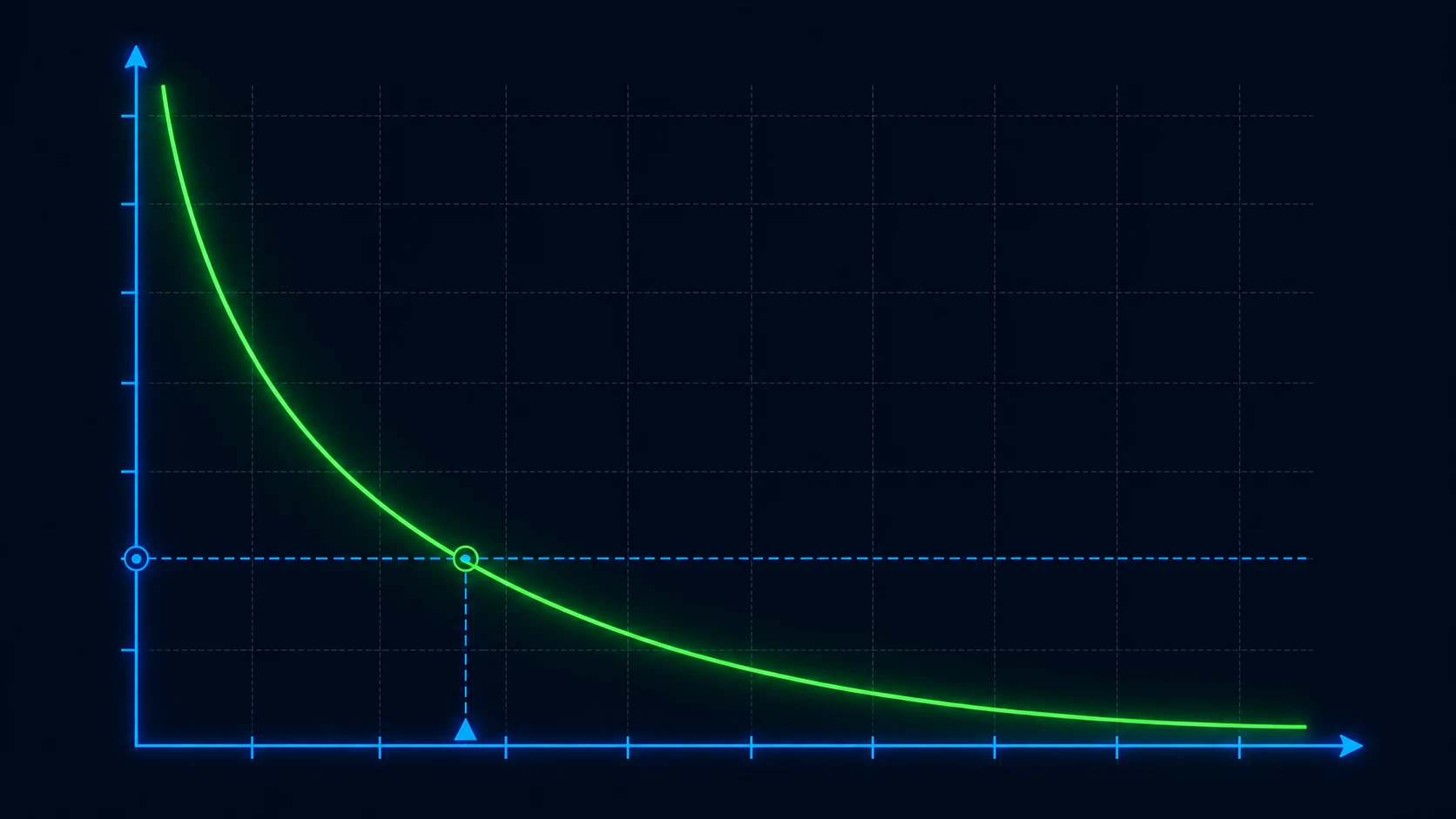
The bearing's operating temperature is one of the strongest controls on fan life because grease and bearing materials age faster as temperature rises. But the relationship is model- and test-specific. SANYO DENKI publishes L10 against stated ambient conditions, voltage and operating mode; its technical guidance does not turn one temperature multiplier into a universal guarantee for every fan.
Use published points instead of inventing a new rating from a headline value. NMB, for example, states 30,000 hours L10 at 40°C for a particular 25 mm sleeve-bearing model. If the medical device runs hotter, ask for the selected model's life curve or test result at the relevant condition. Do not silently extrapolate a 40°C catalogue value to a 55°C enclosure unless the supplier has defined the method and accepted the estimate.
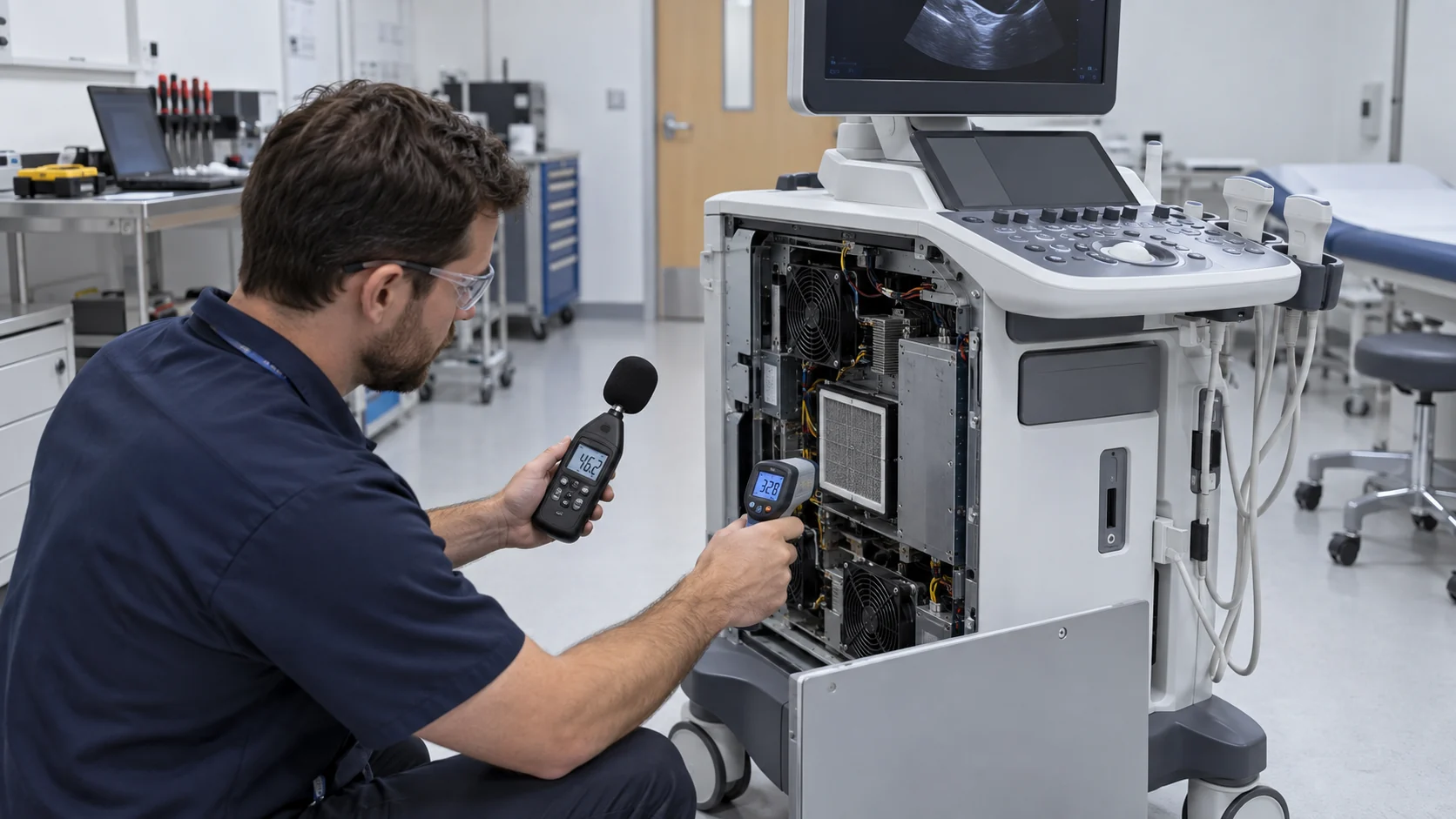
Temperature also changes the surrounding system: hot air reduces the available thermal margin, filters can load faster, and electronics near the fan may have their own limits. Measure inlet air, outlet air, bearing-adjacent temperature where practical, fan speed and current during a representative hot run. A cooler, cleaner airflow path is a sound reliability improvement; the numerical life claim still needs to come from the selected fan's evidence.
Mounting, dust and load — the quiet killers of a long-L10 design
Temperature is not the only variable that changes field life. Mounting orientation, dust, fibres, oil mist, vibration and impeller deposits can alter the bearing load and the airflow available to the device. A sleeve-bearing fan may have a specified orientation limit; a ball-bearing fan may tolerate a wider range, but the selected model's drawing and life data still control the decision.
Speed control and cycling should be treated as test variables, not universal life multipliers. Lower speed can reduce noise and fan stress, but it can also reduce cooling margin; repeated starts can impose a different duty than steady operation. Record the actual PWM or voltage profile, starts per day, inlet temperature, pressure drop and fan current, then ask the supplier to validate that duty. Fan electronics and capacitors also need their own temperature and endurance review.
The practical rule is simple: keep the fan cool, clean, mechanically stable and inside its specified operating envelope. That improves reliability without pretending that a generic formula can predict the service life of a complete medical device.
- Follow the selected fan's orientation, mounting and vibration limits; do not assume all sleeve or ball-bearing fans behave the same way.
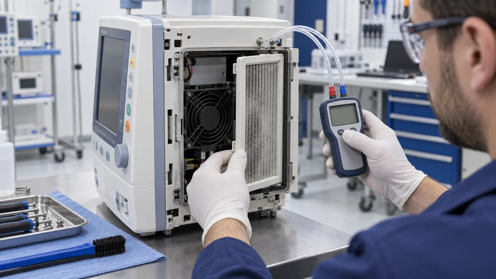
- Control dust, fibres, oil and condensation with the device's filter and airflow design; verify the loaded filter rather than only the clean one.
- Validate the real speed-control and start-stop profile, including minimum controllable speed, restart behavior and fault response.
- Measure the fan inlet temperature and pressure working point in the representative enclosure, then compare the result with the supplier's stated life conditions.
The fleet math — turning L10 into spares and service intervals
L10 becomes useful when it is connected to a real fleet. For example, a device family with 500 fans running 8,760 hours per year should record each model's stated L10 condition, actual inlet temperature, speed profile and replacement history. The calendar conversion is simple arithmetic, but the life value itself should come from the selected fan's evidence rather than a universal temperature or speed formula.
Do not schedule every replacement on the L10 date as if all fans fail together. L10 is a population statistic, not a synchronized end-of-life date. Combine the supplier's life data with incoming inspection, field returns, fan-speed or alarm logs, environmental records and the clinical risk of a cooling loss. That gives the service team a defensible interval without overstating precision.
L10 describes a bearing wear-out mode; the fan's electronics, connector, impeller contamination, corrosion, condensation and mechanical damage can fail earlier. Track those as separate failure modes and keep spares based on the actual device fleet. A useful service plan treats the fan as a monitored subsystem, not a bearing number with blades attached.
Reliability you can see — FG and alarm signals turn a fan into a monitored part
A long-L10 bearing is not a reason to wait for a thermal alarm. A 4-wire fan with FG (tachometer) or RD (alarm) can give the controller speed or fault information, allowing the device to detect a stalled, disconnected or unexpectedly slow fan before the airflow disappears. The signal does not directly measure grease life, so its behavior and wiring thresholds must be defined with the fan supplier.
Do not use a universal 70% threshold as a medical reliability rule. IPC-9591's historical material describes a sustained speed reduction of 15% or more as one failure criterion under its defined test approach, while the selected fan and device may require a different acceptance window. Set the alarm from the fan's commanded speed range, startup behavior, minimum cooling requirement and a healthy baseline, then test nuisance alarms and fault coverage.
Trend speed, current, vibration or acoustic changes only when the device can measure them consistently and the team knows how to interpret the baseline. For equipment that cannot be silently sick — a ventilator, an infusion pump, a blood analyser — FG or RD is valuable because it turns loss of fan function into an explicit system event. It is a monitoring layer, not a substitute for bearing-life qualification.
Customize the reliability target, then prove it in the device
Bearing life becomes useful when the fan is matched to the medical device's heat, mounting, duty cycle and service reality.
MEGA Tech can support medical equipment teams from the reliability requirement rather than selecting a bearing from a headline number. We review operating temperature, mounting orientation, dust and filter exposure, speed range, start-stop profile, available space, airflow and pressure target, noise limit, voltage and feedback needs. That lets the bearing, motor, control and mechanical configuration work together for the actual device duty.
The fan can be customized around frame size and thickness, airflow and static pressure, dual-ball or other bearing configuration, PWM response, FG or RD feedback, connector and cable length, rotation direction, mounting and environmental protection. For a new device or a small first build, we can develop a practical sample around the representative enclosure and help the engineering team compare temperature, noise, vibration, speed stability and service-life assumptions before production is fixed.
Validation should run the fan in the real or representative mounting and airflow path, including hot operation, filter condition, normal speed control and fault feedback. We refine the configuration with the customer, document the approved performance window and then move it into reliable, repeatable production so the replacement fan remains consistent across the device fleet.
- Define bearing temperature, mounting, dust, duty cycle, airflow and pressure targets.
- Customize bearing, speed, control, feedback, wiring and mounting around the device.
- Validate thermal, acoustic, vibration and alarm behavior in the representative enclosure.
- Transfer the approved configuration into consistent production and service supply.
Engineer FAQ: Medical Fan Bearing Life and L10
Reliability claims become useful only when the life metric, temperature, speed, mounting and failure-detection plan are stated together.
Q: What does L10 tell a medical equipment engineer? A: It is a population wear-out measure under stated conditions, not a guarantee for one fan or a fixed replacement date. Keep the model, bearing, temperature, speed, voltage, mounting and test method attached to the value.
Q: Is MTBF interchangeable with fan L10? A: No. MTBF and bearing L10 answer different reliability questions and use different assumptions. Compare each metric only within its proper evidence and do not use a large MTBF number to replace bearing-life data.
Q: Does dual-ball automatically make a fan suitable for medical equipment? A: No. Bearing choice depends on temperature, orientation, vibration, contamination, speed, duty cycle, noise and the selected model's life evidence. Validate the complete fan in the representative device.
Q: How does temperature affect the life claim? A: Temperature changes grease, bearing and electronics stress, but there is no universal multiplier for every fan. Request the selected model's life data at the relevant inlet temperature and duty, or define an agreed test method before extrapolating.
Q: How should a medical device detect a fan that is fading rather than stopped? A: Establish a healthy baseline for speed, current, airflow, noise and temperature, then define FG/RD or other monitoring thresholds and the system response to underspeed or thermal drift. A tachometer alone does not prove airflow or remaining bearing life.
- Tie every numerical answer to voltage, speed, temperature, mounting and test condition.
- Separate catalogue maximums, engineering estimates and measured application results.
- Use the FAQ to define the next measurement or sample-validation step.
Checklist — a medical fan you can trust to outlast the warranty
A checklist for turning a fan into a low-maintenance, fail-safe medical component:
- Select the bearing and fan model from the actual duty: continuous hours, inlet temperature, mounting, dust, vibration, airflow and pressure.
- Record L10 with its test conditions and use it for the bearing wear-out discussion; keep MTBF separate as an electronics reliability statistic.
- Do not apply a generic temperature, speed or start-stop multiplier unless the fan supplier defines and accepts the method for the selected model.
- Keep the airflow path cool and clean, and validate the loaded filter, pressure working point and fan current in the representative enclosure.
- Follow the selected drawing's orientation and mounting limits; verify vibration, connector retention and service access.
- Use FG or RD when the device needs fan-state monitoring, then set thresholds from the fan's startup behavior, operating window and measured healthy baseline.