A Quiet Medical Device Still Needs a Proven Thermal Path
The fan that sounds acceptable in a quiet room may still fail when the filter loads, the enclosure is cleaned or the device enters a high-processing mode.
Medical monitors, ultrasound consoles, laboratory analyzers and portable diagnostic systems often operate close to people and sensitive measurement hardware. The cooling fan must remove electronics heat without adding an irritating tonal peak, excessive vibration, electromagnetic interference or an alarm that the software cannot interpret. It must also keep working after repeated cleaning, filter replacement, transport and long standby periods. These constraints make fan selection a system problem rather than a search for the lowest catalogue dBA value.
The protected function may be clinical measurement, image processing, display stability, data storage or a safety-related alarm. If cooling loss can degrade that function, the risk analysis must define what happens in normal and single-fault conditions. IEC 60601-1 addresses basic safety and essential performance at the medical-equipment level; a fan supplier can provide component data and validation support, but a fan label does not certify the complete device.
This article gives a practical workflow for specifying a medical equipment fan: identify the limiting heat source, define the patient-side acoustic boundary, measure the installed pressure, test filter and cleaning states, validate PWM/FG/RD behavior, check EMC and vibration, and prove the recovery path after a fan fault. It also shows which MEGA Tech fan configurations are usually worth evaluating: a large low-speed axial fan for open cabinet paths, a compact blower for a restrictive duct, and a custom PWM/FG/RD assembly when the product needs adaptive cooling and early fault detection.
Define the Heat Load by Device State
The monitor or analyzer is not thermally identical in standby, acquisition, image processing and charging states.
List the losses from the processor, display backlight, power conversion, storage, sensors, pumps, lamps, transducers and control electronics. Then separate the states that a user can create: cold start, standby, continuous acquisition, maximum image-processing load, battery charging, transport, service mode and alarm operation. A portable monitor may have low average heat but a short high-power charging interval. An ultrasound console may have a stable thermal load but a narrow acoustic limit next to the operator and patient.
For a screening calculation, assume 180 W of heat enters the enclosure and the design allows a 12 K air rise. With rho = 1.2 kg/m³ and cp = 1,005 J/(kg·K), Q = W/(rho × cp × delta T) gives approximately 44.7 m³/h. That value is not a fan selection; it ignores filter, duct and heat-sink pressure, local hot spots, recirculation and the temperature limit of the critical component. A practical design may need a different airflow or a blower if the path resistance is high.
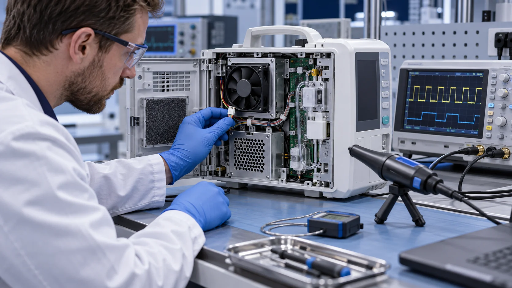
Measure heat at the limiting component, not only at the cabinet outlet. A processor heat sink, power converter or display driver may reach its limit before the average enclosure air temperature becomes alarming. Record inlet air, component case or heat-sink temperature, exhaust air, fan command, fan feedback, power state and ambient. The acceptance limit should state the measurement method and uncertainty.
Animated Model: Noise and Temperature Change with the Operating State
Adaptive speed can reduce idle noise, but only when the control range and fault feedback are validated.
A fixed-speed fan may cool the maximum load, but it can make a monitor or console unnecessarily loud during standby. PWM control allows the device to reduce speed when heat is low and increase airflow during acquisition, charging or an alarm response. The control curve must retain enough headroom for the maximum installed pressure and must avoid an unstable low-duty region where the fan starts and stops repeatedly.
The animation is a qualitative explanation, not a product acoustic measurement. It separates three checks that are often mixed together: useful airflow at the component, perceived sound at the patient or operator position, and control response as heat changes. A fan can be quiet at free air and loud after a grille or duct creates blade-passing tones. Conversely, a larger fan at lower speed can reduce tonal energy if the enclosure has enough space.
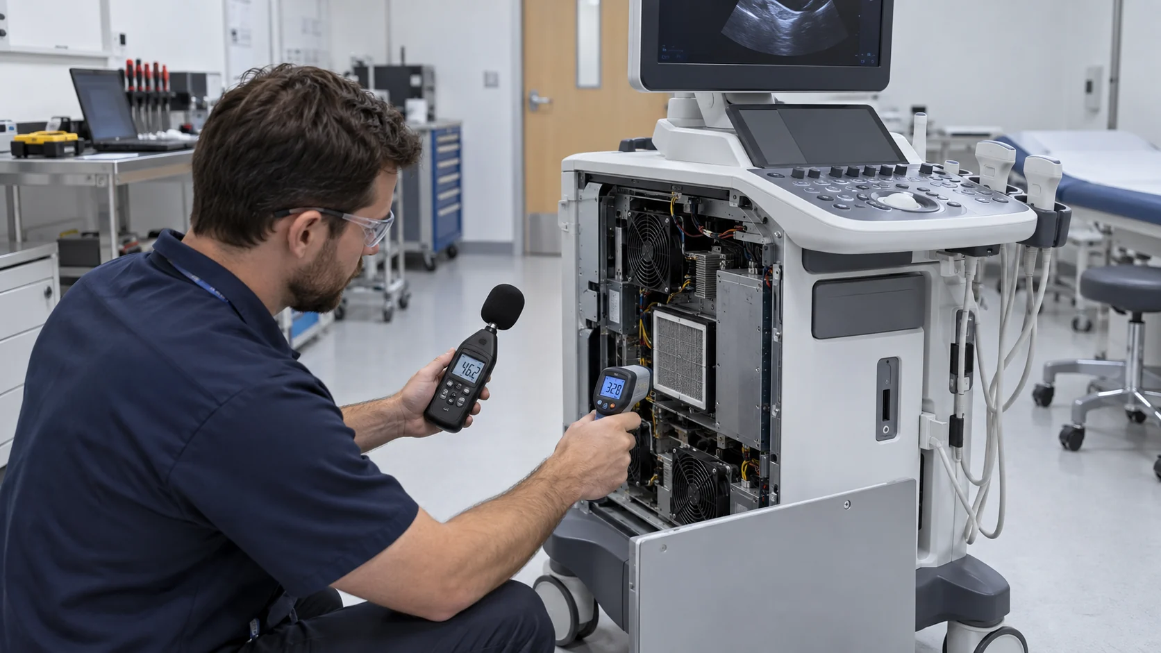
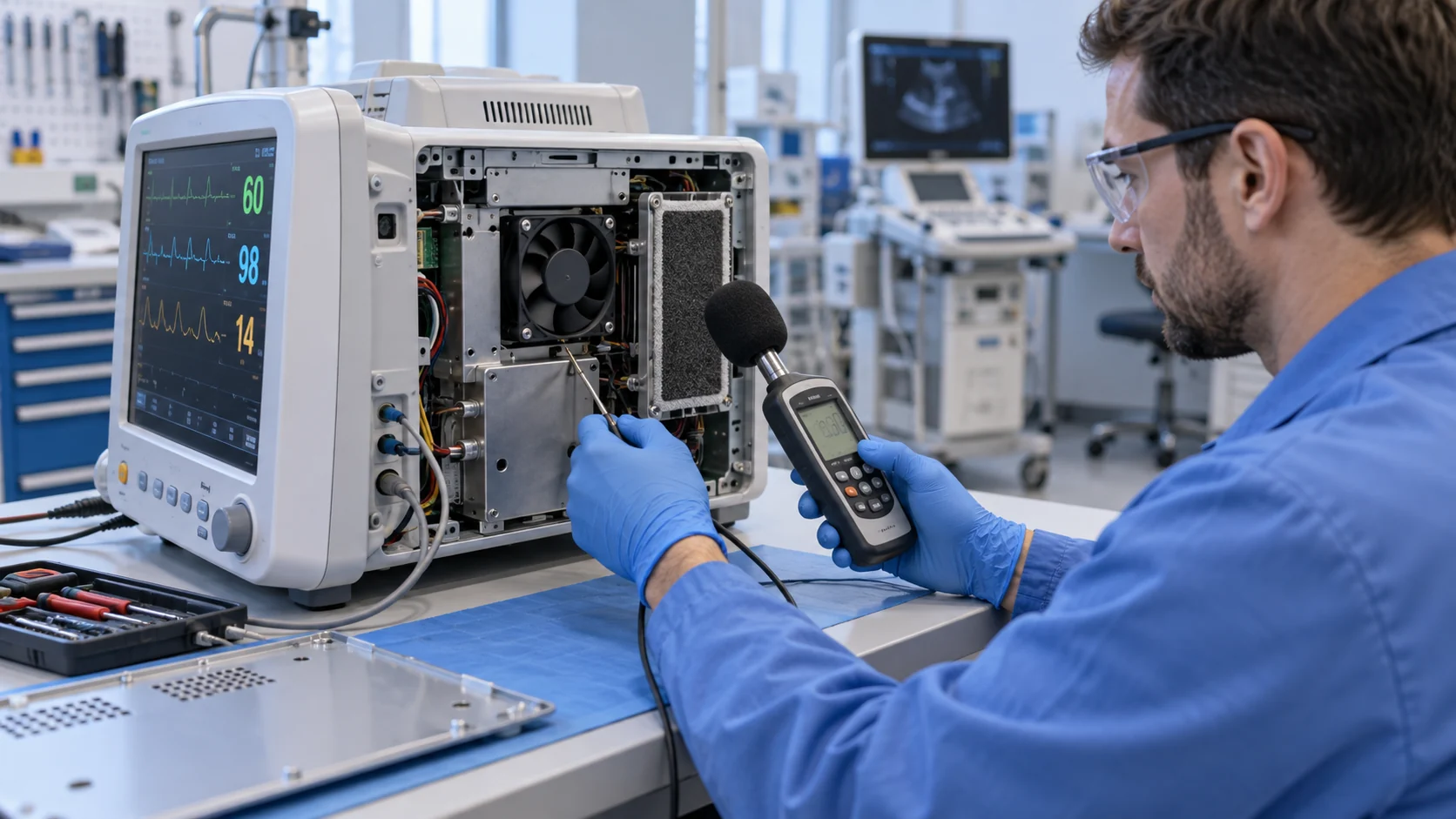
Use the real product enclosure, final panel, filter, acoustic lining, cable routing and mounting hardware during the test. Measure broadband sound pressure and identify tonal peaks rather than publishing only one overall dBA number. Record fan speed, PWM duty, supply voltage, distance, microphone position and the device operating state so a later design change can be compared fairly.

Select Axial or Blower from the Installed Pressure
The air-path topology decides whether a quiet axial fan or a compact centrifugal blower is the better starting point.
A large low-speed axial fan is often a good fit when the air path is short, the heat sinks have open face area and the product has room for a larger frame. It can deliver useful flow with lower rotor speed, but it still needs an inlet, outlet and grille designed to avoid distortion. A compact fan forced through a dense filter, narrow duct or high-fin-density heat sink may operate close to its pressure limit and produce more noise than expected.
A centrifugal blower is worth evaluating when the device has a long duct, narrow outlet, filter, acoustic labyrinth or a defined pressure requirement. The blower can maintain pressure as flow changes, but it may introduce different tonal behavior and needs careful inlet and outlet sealing. Do not choose it merely because the word medical implies high pressure; measure the system resistance first.
The selection target is the intersection of the fan P-Q curve and the installed system curve. For a new device, provide the heat load, airflow target, pressure estimate, envelope, voltage, noise position, control interface and filter details. For a replacement, provide the original part number and measured operating point. Same frame size, voltage and free-air CFM do not establish equal cooling.
| Starting option | Where it fits | What to verify |
|---|---|---|
| Large low-speed axial fan | Open path, low-to-moderate resistance, strict noise target | Installed pressure, tonal peak, mounting vibration, headroom and airflow distribution |
| Compact high-static axial fan | Limited frame space with a short but restrictive path | Heat-sink pressure, filter loading, PWM range, temperature and acoustic spectrum |
| Compact centrifugal blower | Long duct, narrow outlet or higher static pressure requirement | Blower curve, inlet sealing, outlet noise, motor heat and duct leakage |
| Custom fan assembly | Special connector, control, feedback, geometry or low-volume prototype | Sample iterations, P-Q data, EMC, reliability, cleaning and final enclosure validation |
Cleanability and Filter Loading Are Part of the Product Design
A filter that protects the electronics can also become the reason the device overheats or becomes noisy.
Specify how the device is cleaned and serviced. Wipes, disinfectant vapour, dust, lint, gel residue and repeated filter removal can affect the fan frame, gasket, connector and bearing environment. A removable filter may be easy to clean but difficult to reseat consistently. A sealed panel may protect the electronics but force a smaller, higher-pressure fan. The mechanical design should define the cleaning boundary rather than assuming the fan is unaffected by the procedure.
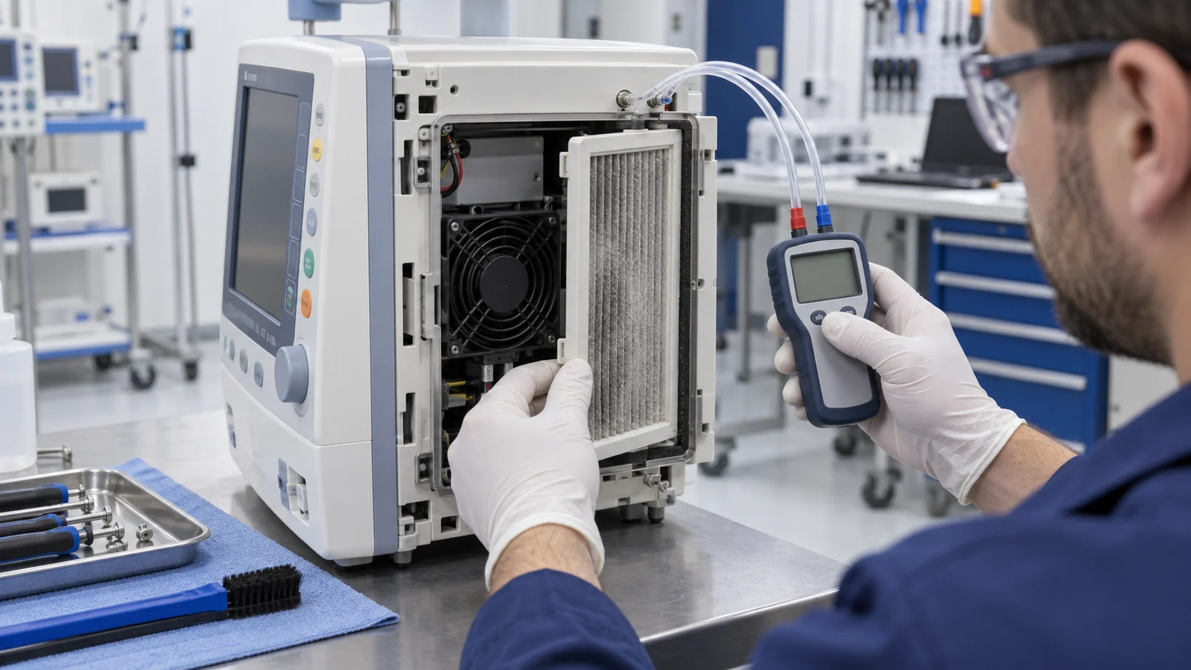
Measure filter differential pressure at the required airflow in clean and service-limit states. If the device has no replaceable filter, test the contamination or cleaning condition that represents the expected service life. A fan alarm based only on RPM may miss a blocked filter because the rotor still turns. Combine fan feedback with temperature, pressure or a validated thermal response so maintenance occurs before clinical performance is affected.
The filter frame must be sealed against bypass. Air leaking around the element can contaminate the heat sink while the fan appears to have acceptable flow. Test the final gasket, latch, door, cable opening and service-panel assembly. Record the filter state in the risk and verification documentation.
- Define the cleaning agent and service method before selecting the fan material and connector.
- Measure clean and loaded filter pressure at the real product airflow.
- Seal the filter frame so protection does not bypass the intended air path.
- Use pressure or temperature evidence with FG/RD; RPM alone is not a proof of cooling.
- Verify that the fan and filter can be serviced without disturbing patient-side safety functions.
Noise Is a Spectrum and a Mounting Problem
An overall dBA value can hide a tonal peak that users find objectionable.
The acoustic result depends on fan speed, blade-pass frequency, inlet distortion, outlet turbulence, grille geometry, duct resonances and structure-borne vibration. A fan that meets a datasheet sound-pressure value in an open test may create a strong tone when mounted behind a narrow slot. The panel can amplify the vibration, and a loose filter frame can rattle during speed changes.
Start with the largest practical fan at the lowest speed that meets the loaded working point. Add PWM so standby is quieter, but validate the full ramp rather than only the minimum and maximum commands. Use isolation mounts or a gasket when they improve vibration transmission without compromising the panel seal. Check startup, speed changes, alarm speed and recovery after a blocked-filter event.
Measure at the position that matters: beside the patient, operator, bed or clinical workstation. Record the background level, microphone location, weighting, bandwidth, fan command, device state and room condition. For a design review, show both the overall dBA and the spectrum so a claimed noise improvement can be linked to a real tonal change.
PWM, FG and RD Support a Safer Control Strategy
Adaptive speed and fault visibility are useful only when the complete interface is tested in the device.
A 4-wire PWM fan can let the medical device reduce sound and power in low-load states, then respond quickly to a temperature or processing event. FG or tachometer feedback can show whether the rotor is actually turning. RD or locked-rotor output can provide a direct fault signal. These signals are not automatically compatible with every controller; check logic levels, pull-ups, pulse count, polarity, startup timing and cable routing.
Test the fan interface during EMC-relevant switching conditions, display refresh, wireless communication, motorized mechanisms and power-supply transitions. A false tach signal can hide a cooling failure, while a noisy control line can create a nuisance alarm. The alarm response should define whether the device reduces function, alerts the operator, switches to a redundant fan or enters a safe state.
For a custom fan, MEGA Tech can support PWM, FG, RD, connector, wire length and mounting changes, but the medical-equipment manufacturer owns the final alarm, risk-control and essential-performance verification. We recommend validating the interface from startup through service and single-fault conditions before freezing the BOM.
EMC, Vibration and Reliability Need One Integrated Test
A fan can pass airflow and noise checks but still create an integration problem through electrical or mechanical coupling.
Route fan power and feedback away from sensitive measurement, display and communication wiring where practical. Test the fan motor driver, PWM edge rate, grounding, connector and cable shield arrangement in the final enclosure. The fan itself is one part of the EMC path; the wiring and panel cutout can be equally important. Do not claim IEC 60601-1 or IEC 60601-1-2 compliance for a fan alone unless the relevant evidence and scope are explicitly defined.
Vibration matters in portable and mobile medical equipment. Check the fan after transport, repeated door opening, tilt, handle movement and any pump or motor operation. Verify that the mounting does not loosen and that the filter frame does not become a rattle source. Bearing choice should reflect orientation, temperature, continuous duty and expected service life; it should not be selected from a generic ranking that ignores the actual application.
Reliability validation should include fan stop, slow fan, blocked filter, disconnected feedback, restart, brownout and temperature recovery. The report should connect each fault to a detection time, device response and user-visible indication. This is more valuable than a long nominal-life claim without the product’s real thermal and service conditions.
How MEGA Tech Can Support a Medical Fan Sample
We help medical-equipment teams compare low-noise axial, compact blower and custom feedback options against the installed path.
MEGA Tech can evaluate low-noise DC axial fans, compact blowers, PWM-controlled fans and FG/RD feedback configurations for monitors, ultrasound systems, laboratory analyzers, imaging accessories and medical electronics cabinets. The useful recommendation depends on the actual heat load, pressure, noise position, filter, mounting, supply voltage, cleaning boundary and service life. We can also assess replacement options for established brands when the same performance envelope is required at a more competitive cost.
For a first engineering review, send the device heat load by state, limiting component temperature, airflow path or enclosure drawing, filter and grille pressure, available fan space, voltage and connector, control and feedback requirements, noise limit and cleaning or environmental conditions. If the project is at prototype stage, a small sample quantity is enough to begin the fit, airflow and acoustic loop. We can adjust speed curve, wire length, connector and mechanical details after the first test.
The deliverable should be a tested sample and an agreed verification record: installed airflow, pressure, temperatures, acoustic spectrum, control response, fault feedback, EMC observations, vibration, service state and production parameters. The fan is not declared medically certified by this process; it is engineered to give the medical-device team reliable evidence for its own design and compliance work.
Engineer FAQ: Medical Equipment Cooling Fans
Short answers for engineering, sourcing and risk-review teams.
Q: Is the quietest fan always the best medical fan? A: No. It must meet the installed pressure and thermal limit, then be evaluated for spectrum, vibration, control, reliability and service conditions.
Q: Can a fan supplier claim IEC 60601 certification for the fan? A: Do not assume that. IEC 60601 applies to the medical electrical equipment and its risk controls; the scope of any component evidence must be stated precisely.
Q: Why use PWM in a patient-adjacent device? A: PWM can reduce idle noise and power while preserving peak cooling, but startup, low-duty stability and acoustic ramps must be tested in the final enclosure.
Q: Why are FG and RD useful? A: FG can indicate speed and RD can indicate a locked rotor or fault, giving the device earlier visibility than a temperature rise alone. Interface compatibility still needs validation.
Q: What should procurement request from a fan supplier? A: Installed P-Q data, operating voltage, acoustic test condition, bearing and life basis, control pin behavior, feedback, environmental limits, samples and a clear statement of certification scope.
Q: Can MEGA Tech support a small medical prototype run? A: Yes. We can review the application, adjust a sample and help validate the fan in the real airflow path before production quantities are fixed.
Medical Fan Design-Review Checklist
Use these questions before freezing the fan, filter and control interface.
- Which device state produces the highest repeatable heat at the limiting component?
- What airflow and pressure are required with the final filter, grille, duct and panel installed?
- Where is the patient, operator or bedside acoustic measurement point?
- Have tonal peaks, vibration and mounting resonance been measured rather than only overall dBA?
- Does the fan remain stable at minimum PWM duty and start reliably at minimum voltage?
- Are FG/RD signal levels, alarms, cable routing and EMC behavior verified in the final device?
- What happens after fan stop, slow speed, blocked filter, disconnected tach or brownout?
- Can the filter and fan be cleaned or replaced without compromising the enclosure and safety boundary?
- Is the component certification scope separated from the complete medical-device compliance responsibility?
- Has a production-intent sample been tested instead of approving the fan from catalogue data alone?