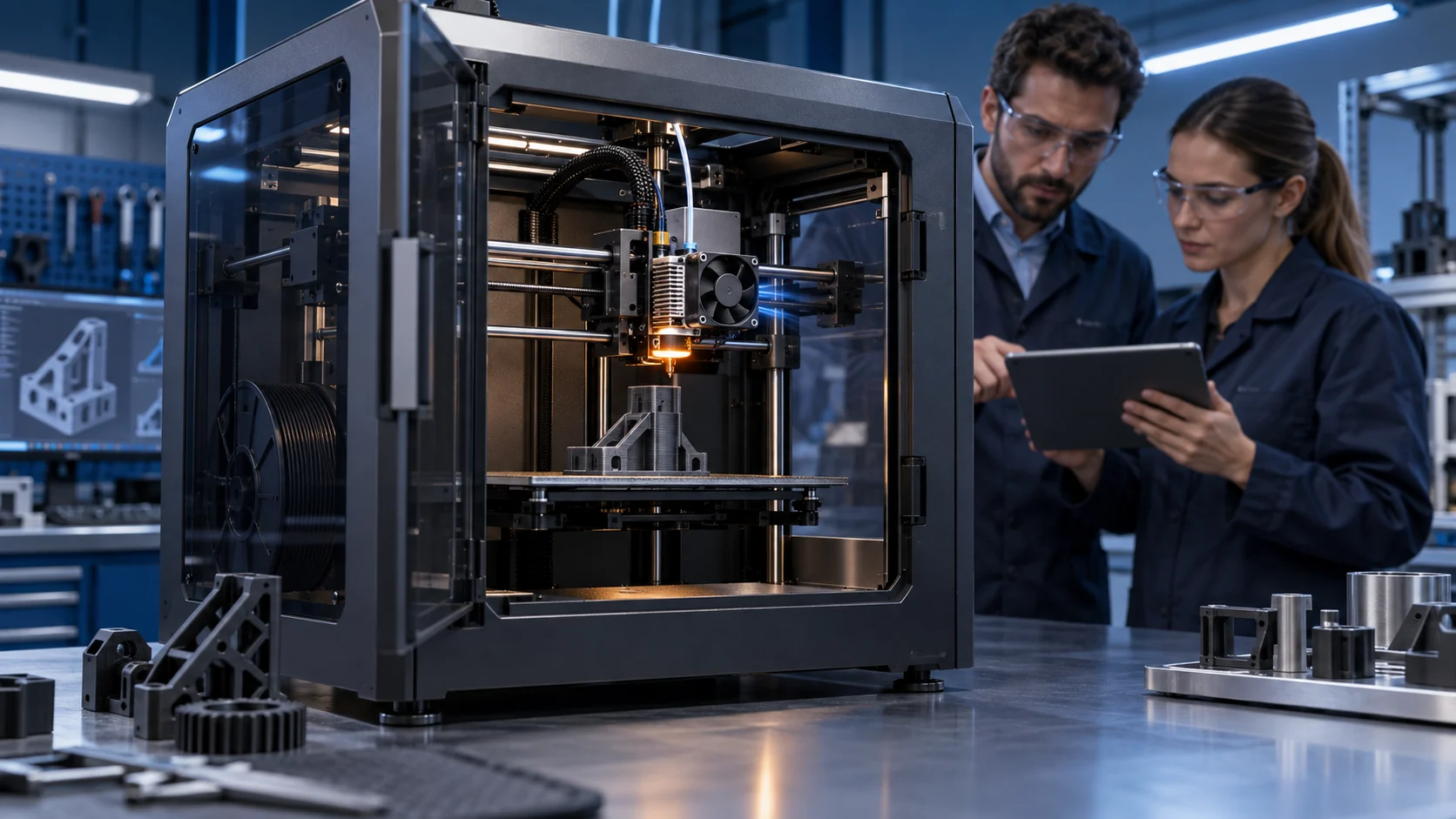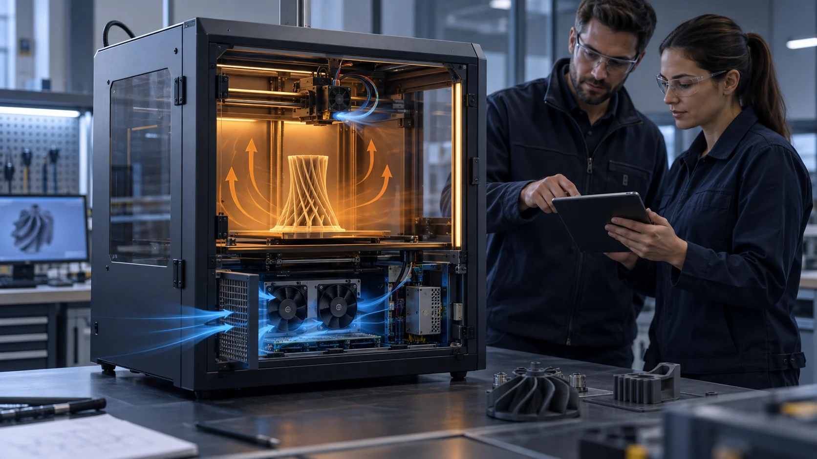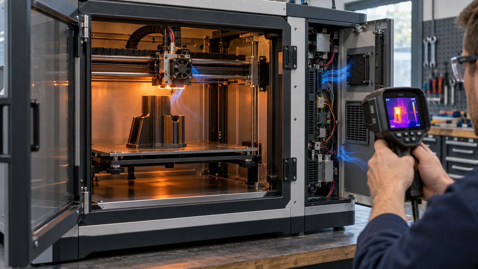
The Printer Did Not Have One Cooling Problem
A heated-chamber printer can have a hotend clog, a warped part and an overheated controller at the same time, even though all three symptoms are described as a fan problem.
The hotend heats the melt zone, the part-cooling duct shapes air around the newly deposited layer, and the electronics bay protects the controller, drivers, power supply and sensors. These loads live in different physical locations and often need different air temperatures, pressure, noise limits and control signals. Treating them as one fan selection problem is a common reason a printer behaves well with PLA but fails during long ABS, ASA, nylon or polycarbonate jobs.
This guide separates the three loops and shows how to validate them on the real printer. The goal is not to publish one universal CFM number. It is to make the air path, pressure drop, thermal state and control behavior measurable before the fan or duct is frozen for production.
The examples below are engineering estimates for explaining the method. They are not limits for a particular filament, hotend, printer or controller. The printer maker remains responsible for heater safety, motion safety, material qualification and regulatory approval.
Loop One: Protect the Hotend Cold Zone From Heat Creep
The hotend heat-sink fan protects the cold side; it is not the same function as the fan that cools the printed part.
Heat creep occurs when heat moves upward from the heater block into the heat break and cold zone. Filament can soften before it reaches the intended melt area, increasing drag, causing under-extrusion and eventually producing a mid-print clog. A fan may still spin while the cold zone receives insufficient useful air because of a blocked guard, poor shroud clearance, recirculated chamber air or an incorrect pressure-flow choice.
The important variables are cold-zone temperature, heat-sink inlet temperature, fan command, voltage, current, feedback, hotend heater state, filament type and print flow. For a heated chamber, the air entering the hotend fan may already be warm. A fan that passed a room-temperature bench test can lose thermal margin when its inlet is 45 to 60°C, so the test should reproduce the chamber state.
As a planning example, if the hotend cold zone must reject 18 W with an allowable air rise of 15 K, the ideal flow from Qv = P/(rho x cp x deltaT) is about 0.001 m3/s, or 2.1 CFM. The required fan is not automatically a 2.1 CFM catalogue part: the heat-sink fin resistance, shroud, guard and warm inlet determine the installed pressure and temperature result.
| Input | Why it matters | Record |
|---|---|---|
| Chamber inlet temperature | Warm air reduces the cold-zone temperature margin | air at fan inlet and cold-zone sensor |
| Heat-sink and shroud | Small gaps can short-circuit or recirculate air | clearance and installed pressure |
| Print flow and retraction | Heat generation changes with material and speed | material, nozzle, flow and retraction |
| Fan startup and minimum duty | A low command may not start reliably when warm | voltage, PWM, current and FG |
| Dust and filament debris | Deposits change balance, clearance and resistance | service state and inspection interval |
Loop Two: Part Cooling Is a Flow-Distribution Problem
A large part-fan number does not guarantee even cooling around bridges, overhangs or thin walls.
The part fan usually needs a duct or manifold to distribute air around the nozzle. The duct adds resistance and may have unequal branches, sharp turns, leakage or an opening that cools one side more than the other. The result can be a strong jet near the inlet and weak flow at the far side, even when the fan reaches its commanded RPM.
For PLA and similar materials, stronger and more symmetric layer cooling can improve bridges and overhangs. For ABS, ASA, nylon and other warping-sensitive materials, excessive or uneven part cooling can increase thermal gradients and reduce layer adhesion. The correct control curve is therefore material- and geometry-dependent; it cannot be copied from the hotend fan curve.
An illustrative 50 mm x 50 mm x 2 mm duct outlet has a 0.001 m2 opening. At an average exit velocity of 8 m/s, the ideal volumetric flow is about 0.008 m3/s, or 17 CFM. Real leakage, contraction and branch losses make the required fan duty higher, while the printer's motion and nozzle shroud can disturb the jet. Measure the installed duct or use a validated flow proxy instead of treating outlet area times velocity as delivered part cooling.
Loop Three: Electronics Cooling Must Not Borrow Hot Chamber Air
The controller bay, motor drivers and power electronics often need a different thermal boundary from the print chamber.
Moving electronics into a heated enclosure can shorten component life and reduce control margin. A side or rear electronics bay may need its own filtered inlet and exhaust path, with the fan selected for the grille, filter, cable openings and heat sinks in that path. If the fan pulls from the chamber, its inlet temperature and the electronics temperature can rise together while the printer appears to have plenty of airflow.
For a simple estimate, suppose the electronics bay dissipates 80 W and the design allows a 10 K air rise. The ideal airflow is about 13.8 CFM. If a filter and grille add 100 Pa and the internal path adds another 60 Pa, the selection point is roughly 14 CFM at 160 Pa before service margin. A free-air rating of 14 CFM does not prove that the controller bay receives 14 CFM at this pressure.
The electronics loop should be checked during heater warm-up, steady heated-chamber printing, motion peaks and power-supply load. Measure the controller hot spot, driver heat sink, power supply inlet, fan inlet, fan current, command and feedback. If the fan reaches its maximum command while the controller still approaches its limit, correct the air path before simply increasing the nominal fan size.
Interactive: Watch the Three Loops Respond to a Heated-Chamber State
The animation shows why one fan command cannot represent hotend protection, part cooling and electronics cooling at the same time.
Use the model to create the test plan. In a cool chamber, the electronics loop may have low duty while the part fan changes rapidly with layer geometry. In a heated chamber, the hotend cold-zone fan may need a higher minimum duty, while part cooling may need to remain limited to protect layer adhesion. The electronics bay may require a separate filtered path rather than more chamber circulation.
A production controller can combine chamber temperature, hotend state, material profile, heater power, electronics temperature and fan feedback. The fan supplier cannot choose that complete algorithm without the printer's system data, but the sample should provide repeatable command response, startup margin, feedback behavior and pressure-flow evidence for the controller team.

High-Temperature Materials Change the Fan Selection
The same printer can require different airflow priorities for PLA, ABS, ASA, nylon, PC and high-flow engineering materials.
PLA commonly benefits from strong, well-distributed part cooling, while enclosed high-temperature materials often need a warm and stable chamber with limited part cooling. The hotend cold zone still needs protection, but its inlet air may be hot and the filament flow may be higher. Electronics may need to be isolated from the chamber regardless of the material profile.
Do not turn a material rule into a fan specification without checking the physical duty. A 30% command on one fan and a 30% command on another do not represent the same airflow, pressure or acoustic output. Fan frame, blade, motor, bearing, duct, voltage and control interface all matter.
For a first sample, compare at least two operating points: a room-temperature PLA-style profile and a heated-chamber engineering-material profile. Keep the same measurement points and log material, nozzle temperature, chamber temperature, print speed, extrusion flow, fan command, voltage, current, FG or tach and the resulting print-quality observation.
Noise, Vibration and Print Quality Are Coupled
The quietest fan on a bench may not be the quietest fan once its duct, guard and printer panel are installed.
Part-cooling blowers can create tonal noise when their blade-passing frequency interacts with a duct or grille. A hotend fan mounted on a moving toolhead adds mass and can transfer vibration into the carriage. An electronics fan can excite a sheet-metal panel or become louder as a filter loads. Measure at the operator position and near the toolhead, not only at a fixed bench point.
The validation should include idle, heater warm-up, steady print, bridge or overhang event, high-flow motion and fan fault response. Correlate sound with RPM or PWM, current, temperature and print result. If a tone appears at one command, a different blade design, PWM frequency, mounting isolation or duct transition may solve it more effectively than simply reducing RPM.
For replacement projects, compare the installed sound spectrum and vibration behavior, not only the dB-A headline. A cost-competitive fan is useful when it preserves the thermal working point, feedback behavior, service life and acoustic acceptance of the printer.
A Repeatable Three-Loop Acceptance Matrix
The best fan selection report makes each loop accountable to a thermal requirement and a measurable state.
For the hotend loop, record cold-zone temperature, heat-sink inlet temperature, fan command, start voltage, current, feedback and clog or extrusion observations. For the part loop, record duct condition, material, print speed, layer temperature behavior, bridge or overhang result, command and acoustic output. For the electronics loop, record controller and driver hot spots, fan inlet temperature, filter state, pressure, current and recovery after a heater or motion step.
Use clean and service states where a filter or grille exists. Repeat warm restart after a long heated-chamber dwell. If the fan stops or FG/RD is lost, document the alarm latency, thermal rise and safe machine response. A fan that passes a cool, clean, no-motion test has not yet proven production readiness.
Separate measured results from planning estimates. A calculated 14 CFM requirement, an illustrative 160 Pa pressure budget and a catalogue maximum are inputs to the experiment, not a substitute for the printer's actual validation.
Where MEGA Tech Fits In
We help 3D-printer teams develop the fan around the real hotend, duct, chamber and electronics envelope.
MEGA Tech can review custom axial fans, compact centrifugal blowers and fan modules for hotend heat sinks, part-cooling ducts, heated-chamber exhaust, filtration and electronics bays. The review can include frame and thickness, pressure-flow behavior, airflow direction, PWM or voltage control, FG/RD feedback, connector and cable exit, bearing selection, temperature range, vibration, noise and small-batch sampling.
For a first review, provide the printer sample or section drawing, hotend and chamber temperatures, material profiles, print flow, electronics heat load, fan envelope, duct and grille, filter condition, voltage and control interface, noise point, service interval and expected quantity. A failed print, thermal image or long-print log is useful evidence for separating heat creep from part-cooling and electronics problems.
We can also evaluate cost-competitive replacements for Sanyo Denki, SUNON, Delta, NMB or ebm-papst fans when the replacement is compared at the same installed pressure, control interface and thermal state. Small first builds are acceptable when the design needs several parameter revisions before production.
Engineer FAQ: 3D Printer Cooling Fan Selection
These questions keep hotend, part and electronics cooling from being mixed into one misleading CFM requirement.
Q: Can the hotend fan also cool the printed part? A: It should not be assumed. The hotend cold zone, part surface and electronics bay have different temperature and airflow requirements.
Q: Why can a printer clog even when the hotend fan is spinning? A: Warm inlet air, poor heat-sink clearance, low pressure at the installed duct, contamination or inadequate cold-zone airflow can all reduce the thermal margin while the rotor still turns.
Q: Is a stronger part fan always better? A: No. Uneven or excessive cooling can change layer adhesion, warping and material behavior. Validate the duct distribution at the material and print speed that matter.
Q: Should electronics cooling draw air from the heated chamber? A: Only after the thermal path is demonstrated. A separate filtered path often gives a clearer electronics temperature margin.
Q: What should be recorded for a replacement fan? A: Installed airflow or proxy, pressure, voltage, current, command, feedback, inlet temperature, hot spots, noise and warm restart behavior.
Q: Can MEGA Tech support small sample quantities? A: Yes. We can start from a printer sample, adjust the fan and interface parameters, build samples and support the validation before production quantities are fixed.
High-Temperature 3D Printer Fan Review Checklist
Use this checklist before changing a fan, duct or electronics-bay cooling strategy.
- Which cooling loop is failing: hotend, part or electronics?
- What chamber, inlet and heat-sink temperatures define the worst state?
- What airflow is required at the installed pressure and duct condition?
- Does the fan start at the minimum declared voltage and warm temperature?
- Were PWM, FG/RD, current and temperature recorded together?
- Is the part-cooling duct distribution symmetric at the actual print speed?
- Does electronics cooling use a protected air source separate from the heated chamber?
- Were clean filter, loaded filter, warm restart and long-print states tested?
- Where is noise measured and does the installed panel or duct create a tone?
- Which values are measured, estimated or owned by the printer safety and material teams?