A Charger Can Pass Rated Power and Still Derate in the Field
The nameplate charging power is not the heat load that the cabinet fan must remove.
An EV fast charger rarely operates at one constant electrical condition. The power stage may ramp quickly when a vehicle connects, hold a high output for part of the session, reduce power as the battery approaches its requested voltage, and then repeat with another vehicle. Ambient temperature, grid voltage, cable cooling, module efficiency, fan control and vehicle demand all change the thermal state. A fan selected from a single maximum-CFM value can therefore look acceptable on a bench and still allow a power module to reach its derating threshold during a repeated charging sequence.
The thermal design must also separate the vehicle-side battery thermal system from the charger cabinet. The vehicle may reduce current because of battery temperature, state of charge or software limits. The charger may reduce output because its rectifier, DC/DC stage, busbar, connector or power-module heat sink is hot. These are different diagnoses. The fan supplier needs the charger cabinet heat source, installed air path and limiting temperature, not only the charger’s output rating.
This article gives a repeatable method to validate the fan working point across a charging power cycle. It covers loss-based heat input, the difference between clean and loaded filters, PWM and tachometer behavior, hotspot measurement, acoustic and energy trade-offs, and a release test that can distinguish charger derating from a vehicle-side limit. A custom fan is valuable when the original catalogue unit cannot meet the required pressure, noise, voltage or service envelope at the real operating point.
Convert Electrical Losses into a Cabinet Heat Budget
Start with the watts that become heat inside the air path, not with the kW delivered to the vehicle.
Create a loss table for the rectifier, PFC stage, isolated or non-isolated DC/DC stage, contactors, busbars, control power supply, fan motors and any internal heater. Use efficiency data at several power levels rather than applying the full charger output as heat. For a 30 kW module at 96.5% efficiency, the conversion loss is approximately 1.09 kW. At 15 kW and a different efficiency point, the loss may not be half of the maximum-load loss. The heat-source distribution also matters because a concentrated power-module heat sink can limit before the cabinet average becomes high.
A screening example illustrates the difference. Assume a 60 kW charger has 96% total conversion efficiency at the design point. The loss is 60 × (1 - 0.96) = 2.4 kW. If 0.3 kW is outside the protected cabinet or transferred through a liquid loop, the air-side fan may need to remove roughly 2.1 kW, plus internal fan and control losses. With a 10 K air rise, rho = 1.2 kg/m³ and cp = 1,005 J/(kg·K), the ideal airflow is about 627 m³/h. This is an engineering estimate, not a product specification; the installed pressure and temperature distribution still determine whether the heat sinks are adequately cooled.
Run the heat budget for multiple states: startup, 25%, 50%, 75% and rated output; repeated sessions; high ambient; low-voltage supply; fan degradation; loaded filter; and a failed redundant fan. Include the thermal mass and time constant of the power module. A short peak may be handled by heat-sink mass while a long moderate session may create the actual limiting temperature. The acceptance test should use the power profile that produces the worst repeatable thermal result, not whichever point is easiest to run.
Animated Model: Power Ramps Move the Fan Duty Point
The fan command should follow heat and pressure evidence, not only a fixed nameplate power threshold.
During a charging session, power-module loss rises and falls with output power and efficiency. The fan controller may respond to heat-sink temperature, inlet temperature, module NTC, cabinet exhaust temperature or a combination of signals. A simple temperature-only loop can react too slowly to a known power step, while a command-only loop may run loudly when the cabinet has little heat to reject. Feed-forward from charger power can be useful, but it must be validated against the actual thermal response and sensor location.
The dynamic diagram is qualitative. It does not represent a particular charger, fan curve or derating limit. Use it to structure the test: log requested and delivered charging power, module temperature, fan PWM or analogue command, FG/RD feedback, inlet and exhaust temperature, filter pressure and ambient conditions. The key question is whether the fan delivers the required air at the pressure created by the final heat sinks, shrouds, filters and cable paths during each state.
If the fan holds RPM while a filter loads, the working point can move to a lower airflow. If the fan is oversized but runs at full speed for every power step, the charger may meet temperature but lose acoustic and auxiliary-power performance. A custom control curve should be based on the thermal time constant, minimum stable speed, alarm behavior, power budget and the required recovery after a high-load session.

Measure the Installed P-Q Point at the Power Module
The fan specification becomes meaningful only after the cabinet resistance is known.
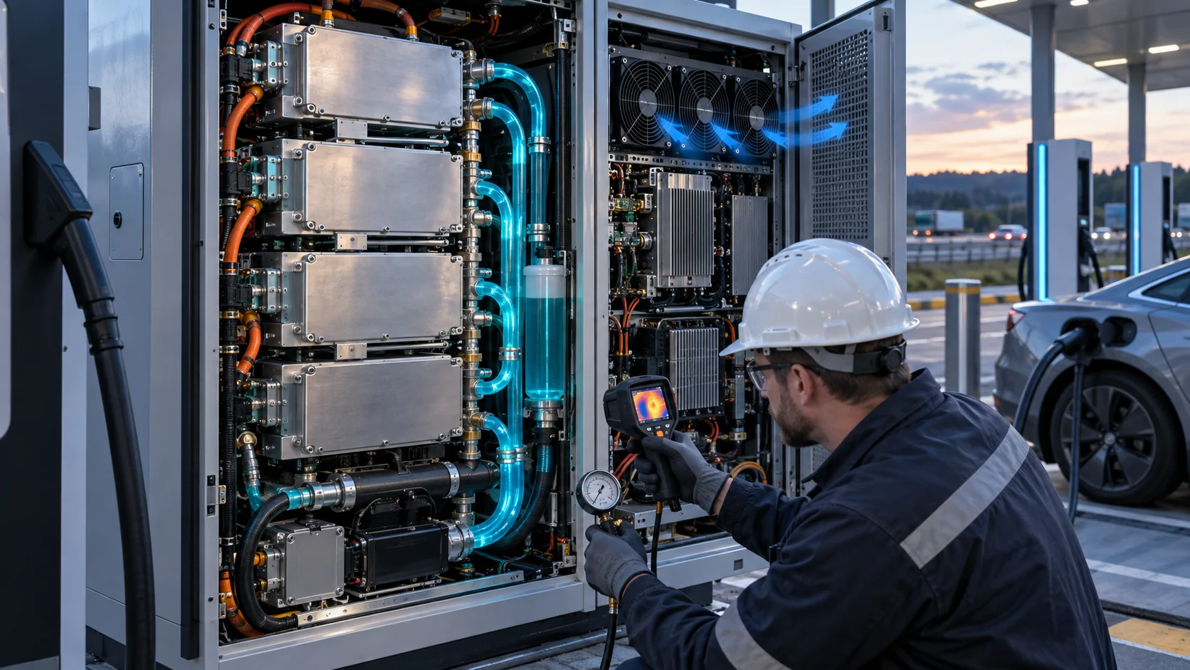
Map the complete flow path from intake to exhaust. Include the filter, weather louvre, guard, heat-sink fin pack, shroud, cable bundles, module spacing, door panel and any liquid-cooling radiator that shares the air path. Look for bypass from the fan directly to the exhaust and for recirculation from a hot module back to the intake. A high free-air number cannot reveal these installation effects.
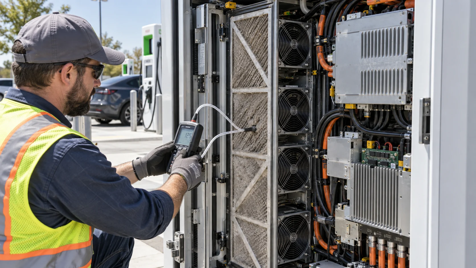
Measure airflow at more than one convenient location. A single exhaust reading can be misleading when part of the flow short-circuits around the heat sink. Use a calibrated flow hood, anemometer grid or another appropriate method, and correlate it with differential pressure across the filter and heat sink. Record fan voltage, command, RPM, current and direction. If the charger uses multiple fans, test fan-to-fan mismatch and the effect of one stopped rotor on the remaining units.
The working point should be checked at clean filter, service-limit filter, high ambient and minimum permitted voltage. If the design uses positive pressure, verify that the exhaust path maintains the intended pressure without opening uncontrolled leakage paths. If the cabinet is sealed, evaluate the internal circulation loop separately from the external heat-rejection loop. An internal fan can improve heat-sink distribution but cannot remove heat without a valid boundary path.
| Validation state | What changes | What to record |
|---|---|---|
| Clean filter / low power | Low resistance and low heat generation | Airflow, pressure, command, RPM, noise and minimum stable speed |
| Rated power / clean filter | Maximum or near-maximum loss | Module inlet and heat-sink temperatures, delivered power and fan energy |
| Rated power / loaded filter | Higher resistance and the same heat source | Filter pressure, airflow loss, derating margin and alarm timing |
| Repeated sessions / high ambient | Thermal mass and ambient reduce margin | Temperature recovery, fan ramp, cycle-to-cycle drift and limiting component |
| One fan failed | Flow distribution and pressure change | Remaining airflow, hot spots, alarm, safe power limit and service interval |
Power-Module Hotspots Are More Important than Cabinet Average
The limiting semiconductor or heat sink can exceed its safe temperature before the cabinet air sensor moves significantly.
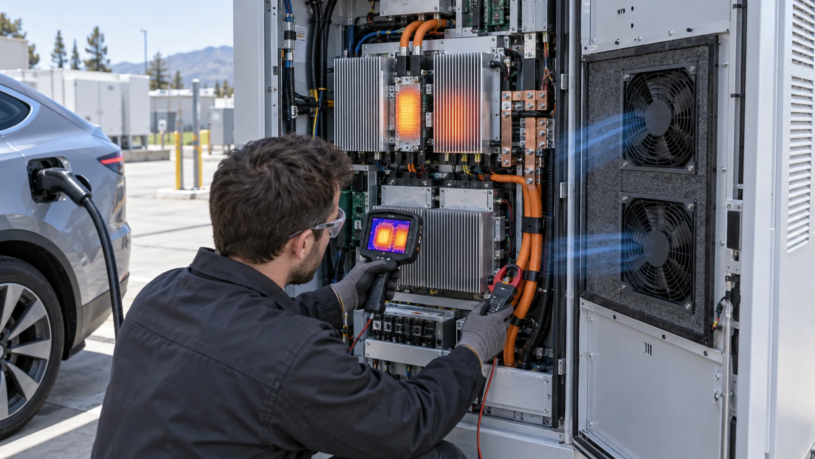
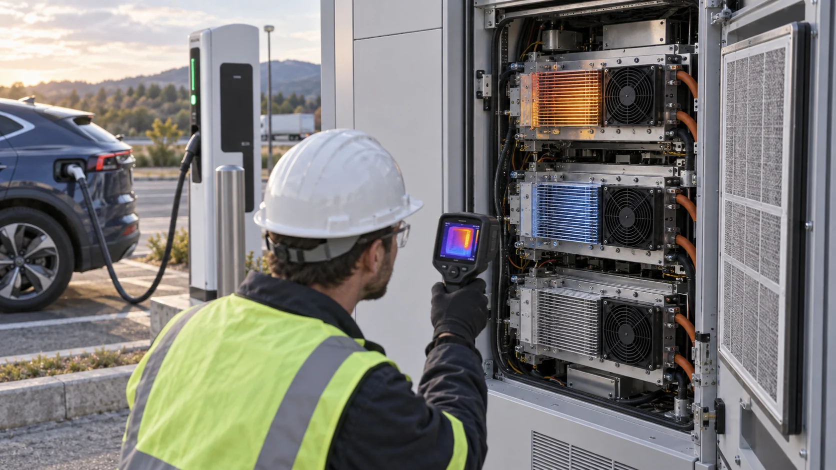
Place sensors near the actual thermal bottleneck: power-module baseplate or heat sink, rectifier inlet, busbar region, capacitor bank, control board and cabinet exhaust. Avoid placing the only sensor directly in the fan jet or at a cool cabinet corner. A fan can create a low local reading while a downstream heat sink receives distorted or insufficient flow. Infrared measurements should account for emissivity and line of sight; thermocouples or embedded sensors may be needed for correlation.
The test should distinguish a thermal protection event from a control or vehicle event. Record the charger’s requested output, delivered output, module temperature, fault code, vehicle demand if available, coolant state for liquid-cooled cable systems, and the time at which power changes. A useful validation plot overlays power, fan command and the limiting temperature. If output falls before the module approaches its limit, investigate software or vehicle constraints rather than increasing fan speed blindly.
Thermal margin is not only the difference between an average temperature and a maximum temperature. It includes measurement uncertainty, manufacturing variation, filter fouling, ambient tolerance, supply voltage, airflow imbalance and the time needed to detect a fan fault. Define the margin at the protected component and state the exact test condition.
Dust, Salt Fog and Filter Maintenance Change the Economics
A charger at a coastal road or dusty fleet depot sees a different fan problem from a clean indoor prototype lab.
Opening the cabinet for air exchange changes the environmental boundary. The filter must control the intended contamination without consuming so much pressure margin that the power module loses airflow. Salt aerosol, conductive dust, oil mist, insects and moisture can affect the filter, fan motor, connectors and heat-sink surfaces. The correct protection level depends on the completed cabinet, not the fan component marking alone.
Define the maintenance state with a measurable pressure threshold or a validated exposure interval. A filter that looks acceptable may have a pressure rise that moves the fan away from its design point. Conversely, a filter may be clean but poorly seated, allowing bypass contamination into the electronics. Include filter replacement access, gasket compression, orientation, service records and what the charger does when the filter alarm is ignored.
When comparing a higher-pressure fan with a lower-power fan, compare the full service cost. A fan that runs faster may recover airflow but increase sound, auxiliary power and bearing stress. A larger fan at moderate speed may have more margin, but only if the enclosure has room and the installed pressure curve supports it. MEGA Tech can help compare these alternatives with the actual filter and heat-sink path.
PWM, FG and RD Must Be Validated During Charging Transients
Control signals are part of the thermal safety chain, not just a convenience interface.
A charger controller may command fans through PWM, analogue voltage, discrete steps or a dedicated motor driver. Confirm the minimum duty that reliably starts the fan, the behavior at low temperature, the response to a sudden power step and the maximum permitted command. Some fans can stall or oscillate at an unsuitable low duty, while a fan with a wider control range can reduce sound and energy during standby.
FG or tachometer feedback should be checked for pulse integrity during switching-noise events and low-speed operation. RD or alarm output should distinguish locked rotor, missing supply and an implausible signal. Test cable routing near high-current switching nodes, connector retention during vibration, restart after a brownout and behavior when one fan is disconnected. The charger should not continue at full power when cooling feedback is invalid unless the system has a demonstrated safe fallback.
For redundant fan arrays, test the failure states the controller can actually detect. A rotor that spins slowly, a fan with blocked intake, a disconnected tach line and a shorted control line may produce different electrical signals. The protection response should be based on useful airflow or temperature evidence where possible, not on one optimistic feedback signal.
Release Test: Reproduce the Charging Session, Not a Static Bench
A credible charger-fan release uses a repeatable power profile, installed resistance and environmental states.
Freeze the charger configuration: power modules, heat sinks, shrouds, filters, fans, cable routing, firmware, sensors, cabinet panels and service clearances. Establish a baseline with clean filters and record the installed pressure and airflow at several fan commands. Then run a power profile that includes startup, ramp, sustained high power, reduced power and a second session before the cabinet returns to ambient.
Repeat the profile at the highest specified ambient and minimum permitted fan supply voltage. Add a service-limit filter or calibrated restriction. Test fan stop, tach loss, alarm response, one-fan failure, restart and power recovery. If the charger is installed outdoors, include the intended rain, dust, salt, solar and humidity boundary or state clearly which environmental tests belong to the enclosure certification team.
The release report should include delivered airflow, static pressure, filter pressure, fan voltage, command, RPM, current, power-module temperature, inlet and exhaust temperature, ambient, acoustic result, derating threshold, alarm delay and recovery time. The report should also identify what was not tested. This makes later replacement or cost-reduction work auditable instead of relying on the statement that the charger was tested once at rated power.
How MEGA Tech Supports a Custom EV-Charger Fan
We help charger manufacturers turn power-module loss and enclosure resistance into a testable fan sample.
MEGA Tech supplies custom DC axial fans, compact blowers and high-static-pressure fan assemblies for EV charging cabinets and power-conversion equipment. We review the power-loss map, heat-sink geometry, filter and grille pressure, fan envelope, voltage range, PWM or analogue control, FG/RD feedback, acoustic target, vibration, environmental exposure, redundancy and service interval. Our goal is to support a meaningful sample at the installed working point, not simply quote a maximum-airflow number.
For an initial review, send charger power and efficiency by operating state, limiting component temperature, charging-session profile, cabinet drawing or photographs, required airflow and pressure, filter data, minimum and maximum supply voltage, control interface, quantity, noise limit and environmental condition. For a replacement, include the original fan part number, measured command, installed pressure if available, and the derating symptom. This information allows a practical comparison with established industrial fan brands while keeping the performance boundary honest.
We can support prototype adjustment, sample matching, P-Q characterization and production transition. The charger integrator remains responsible for high-voltage safety, enclosure certification, grounding, EMC approval, battery and cable thermal management, and the final derating logic. A lower-cost replacement should be accepted only after pressure, airflow, control, reliability and environmental evidence are matched to the application.
Engineer FAQ: EV Charger Cooling Fans
Short answers for a power-cabinet and thermal-derating review.
Q: Can charger output kW be used as fan airflow directly? A: No. Convert the power-module losses that become cabinet heat, then calculate and measure the airflow at installed pressure.
Q: Why can a charger derate when the fan RPM looks normal? A: A loaded filter, heat-sink restriction, bypass path or airflow imbalance can reduce useful flow without a proportional RPM change.
Q: Should fan speed follow charger output power? A: Power feed-forward can improve response, but it must be combined with temperature or other evidence and validated across the thermal time constant.
Q: Does an outdoor fan make the charger weatherproof? A: No. The complete fan, filter, louvre, gasket, drain and cabinet opening must be evaluated by the responsible enclosure and certification teams.
Q: What is the most useful data for a custom fan sample? A: Power loss by state, limiting temperature, charging profile, airflow and pressure, filter condition, voltage, control, feedback, envelope, noise and environment.
EV-Charger Fan Design-Review Checklist
Use these questions before approving a fan, replacement or cost-reduction sample.
- Are charger output power and internal conversion losses separated in the heat budget?
- Which power module, heat sink or connector defines the limiting temperature?
- Does the validation use the actual charging-session power profile and repeated sessions?
- What is the fan working point with the clean and service-limit filter?
- Have bypass, recirculation, cable congestion and fan-to-fan mismatch been measured?
- Does the fan start, control and report FG/RD correctly across the supply-voltage range?
- What happens when one fan stops, tach feedback is lost or the filter alarm is ignored?
- Are dust, salt, humidity, rain, noise, vibration and service access included in the final boundary?
- Does the replacement fan match the installed performance envelope rather than only frame size and rated voltage?