A Cabinet Can Pass Alone and Fail in a Row
The air entering a battery enclosure is a site-level condition, not only a cabinet datasheet condition.
Many battery energy storage system thermal tests begin with one cabinet or one container operating in a controlled environment. That is a necessary component of validation, but it does not reproduce every site condition. When several enclosures reject heat toward the same aisle, the next cabinet may inhale warmer air than the isolated test assumed. The cooling system then starts with less temperature margin before the battery modules, inverter or power electronics reach their operating limit.
This site heat-island effect can be amplified by wind direction, sun exposure, wall spacing, exhaust orientation, acoustic screens, fencing, gravel temperature and the duty cycle of neighboring units. A fan selected from the ambient-weather design point may still be under-sized if the actual intake air is already several degrees warmer because the exhaust path recirculates.
This guide focuses on the fan and air-side evidence: intake temperature, filter and grille pressure, exhaust recirculation, high-ambient margin, control response and maintenance state. Fire protection, gas detection and thermal-runaway procedures must remain under the applicable code, listing, AHJ and system-supplier requirements. A cooling fan is not a substitute for a safety system.
Separate Outdoor Ambient From Cabinet Intake Air
The weather-station temperature is not necessarily the temperature the fan sees.
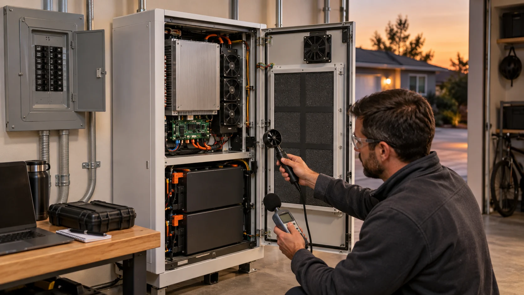
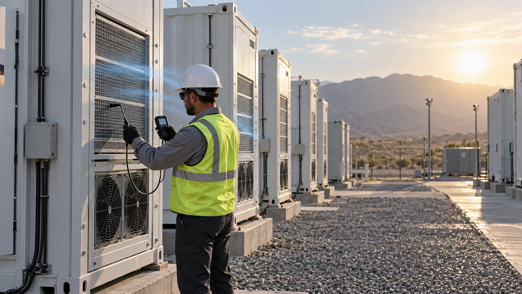
Install or temporarily place sensors at the cabinet intake, exhaust and representative neighboring locations. Record solar condition, wind direction and speed, container operating state, HVAC or fan command, battery charge/discharge power and the spacing between units. A single outdoor sensor at the perimeter can miss the hot plume that enters a cabinet from the adjacent row.
Map both the hot and cold operating scenarios. During low wind, the exhaust plume may remain near the equipment. During crosswind, one row may feed a warmer plume into another row while a different side stays clear. A site can therefore have a lower average temperature and a worse local inlet condition at the same time.
For an illustrative example, the weather sensor reads 38°C, while the first cabinet intake reads 40°C, the middle-row intake 44°C and the downwind intake 47°C during simultaneous discharge. The difference between the nominal ambient and the worst inlet is 9°C. A fan and HVAC test performed only at 38°C would not demonstrate the same thermal margin. These values are an example of the method, not a universal BESS limit.
| Point | Measure | Engineering question |
|---|---|---|
| Weather reference | shade-protected outdoor temperature | what is the nominal design ambient? |
| Cabinet intake | air temperature and RH before filter | what does the fan actually receive? |
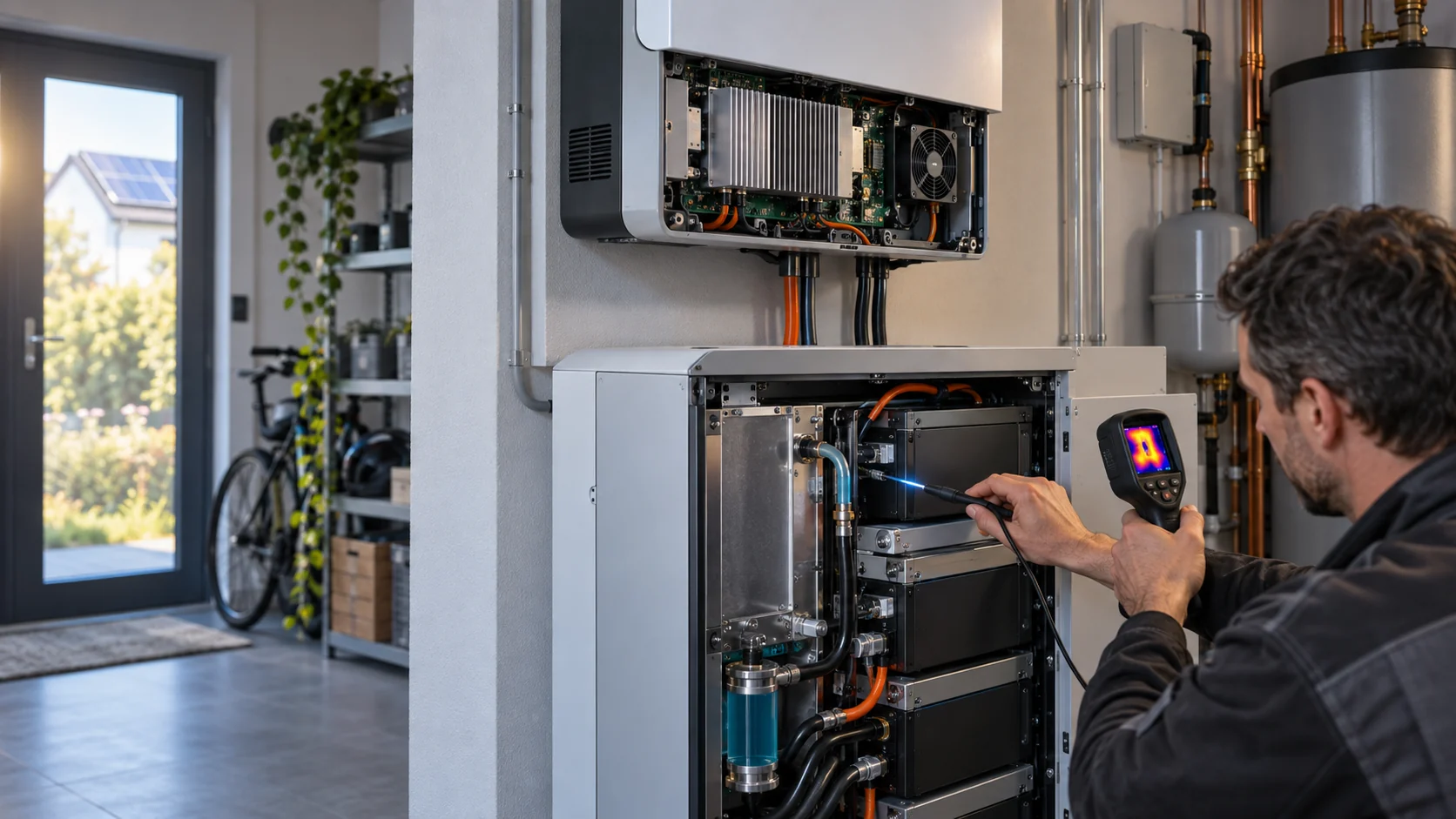
| Filter downstream | temperature and differential pressure | how much margin is lost across the filter? |
| Cabinet exhaust | temperature, flow direction and plume | where does rejected heat go? |
| Neighboring intake | same points on upwind/downwind units | does the site layout create recirculation? |
The Fan Must Carry the Worst Installed Pressure
High ambient does not remove the need to calculate the air path through filter, grille, heat exchanger and enclosure resistance.
List the intake grille, washable or replaceable filter, louvre, coil, heat sink, battery module passage, duct or baffle and exhaust opening. Build a clean-state and service-state pressure budget. The fan operating point is where its P-Q curve intersects the combined system curve. If the filter loads, the system curve moves upward and the useful airflow falls even if the motor still reports normal RPM.
For a worked estimate, suppose an enclosure requires 2,400 m3/h at 180 Pa in the clean state. The intake grille consumes 25 Pa, filter 45 Pa, coil 55 Pa, internal baffles 30 Pa and exhaust louvre 25 Pa. If dust loading raises the filter loss to 90 Pa, the total becomes approximately 225 Pa. The fan must be compared at both 2,400 m3/h and 180 Pa clean, and the required service-state flow at roughly 225 Pa, not at free delivery.
Do not assume that a high-pressure fan automatically solves a hot cabinet. A fan can generate pressure but still create a poor internal distribution, bypass a battery bank or send the hottest air back into the neighboring intake. Pressure, flow direction and temperature mapping must be validated together.
Interactive: Watch Exhaust Recirculation Move the Duty Point
The schematic shows why the same fan command can produce different battery cooling when the site exhaust path changes.
Use the visual as a commissioning prompt. Compare a single cabinet, a full row and the downwind row under the same charge or discharge condition. Record intake temperature, exhaust temperature, differential pressure, fan command, current, battery module temperatures and HVAC state. If the worst cabinet sees warmer air but the control signal uses only the perimeter weather sensor, the control loop is blind to the site effect.
Then test a layout or deflector change without changing the fan. If the intake temperature drops and the fan current remains similar, the improvement came from the air path rather than from motor capacity. If the deflector adds pressure, re-check the P-Q point because the thermal gain may be offset by lost airflow.
The animation is a qualitative model, not a CFD result, fire analysis or universal pressure multiplier. Its purpose is to make the site-level question visible before the team freezes the enclosure layout.

High-Ambient Margin Is More Than a Maximum Temperature Number
A useful margin includes intake temperature, component heat, fan control headroom and service degradation.
Define the high-ambient state using the actual cabinet intake, not only the climate-zone design temperature. Then identify the limiting component: battery cell or module, inverter, power conversion electronics, contactor compartment, controller or HVAC compressor. The fan may protect only part of the heat path, while the refrigeration system or liquid loop protects another part.
For an illustrative thermal balance, a cabinet rejects 7.5 kW through an air path and the measured air mass flow is 0.62 kg/s. Using air specific heat near 1,005 J/(kg·K), the air-side temperature rise is approximately 7,500/(0.62 × 1,005) = 12.0°C. If the intake rises from 40°C to 46°C, the estimated leaving air rises by the same amount before accounting for changes in density, leakage and heat distribution. The battery and electronics do not experience the weather-station number; they experience the installed path.
Leave control headroom for filter loading, fan tolerance, voltage variation, high altitude and a failed or derated unit where the design requires it. A test at maximum PWM with no remaining margin is not a robust high-ambient design, even if the measured temperature passes for a short run.
Filter Loading Changes Cooling and Maintenance Risk
A clean filter is a commissioning baseline; a service-state filter is part of the product requirement.
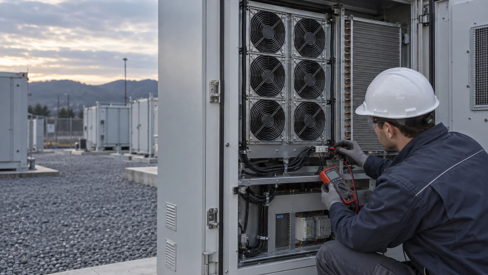
Dust, pollen, salt, insects and construction debris can raise filter pressure over time. The fan may continue to spin at the commanded RPM while airflow through the battery passage falls. If the controller uses only RPM, it may not detect the loss. Add differential pressure, airflow or temperature-spread evidence so the maintenance action is connected to the actual thermal risk.
Set the service threshold from the enclosure's pressure and thermal test, not from a generic HVAC number. For a first estimate, if a clean filter measures 45 Pa and the service limit is 90 Pa, the controller or maintenance team should know whether the fan can still meet the required flow at 90 Pa. If it cannot, the system needs an alarm and replacement interval rather than a promise that the motor will simply run faster.
Test filter removal and replacement access, gasket compression, bypass leakage and the sensor location. A filter differential-pressure tube installed upstream and downstream of the wrong frame can report an attractive number while air bypasses the filter through a gap. Validate the physical measurement path during commissioning.
Cooling Control Must Respect Safety and Shutdown Logic
Thermal management, ventilation and emergency response may have different control priorities.
A BESS fan controller should not be treated as an independent authority during a safety event. The final sequence depends on the battery chemistry, enclosure listing, gas detection, fire protection, thermal-runaway strategy, local code, AHJ decision and system supplier instructions. Normal cooling control may request airflow, while a safety sequence may change or stop equipment, activate exhaust or require a defined isolation state.
NFPA 855 and related ESS guidance cover installation, commissioning, operation, maintenance and hazard-management topics. The engineering team should confirm which fan, damper and exhaust functions are part of the listed system and which are ordinary thermal-management functions. Do not add a fan or change a shutdown sequence without reviewing the complete safety case.
For normal-operation validation, test the handoff between thermal control and the approved safety logic using the system supplier's procedure. Record fan command, alarm state, gas or smoke detection state where applicable, damper position and the operator indication. This protects both thermal performance and the credibility of the safety documentation.
An Anonymous Customer Example: The Downwind Cabinet Became the Limiting Unit
A utility-scale operator found that the isolated cabinet test did not represent the intake temperature of the downwind row during simultaneous discharge.
The customer had several outdoor enclosures arranged in parallel rows. Each cabinet passed its own thermal test, but one downwind group showed a higher battery-module temperature during a hot afternoon. The initial response was to increase the fan command on every cabinet. That increased noise and auxiliary power, while the downwind group still had a smaller temperature margin than the upwind group.
MEGA Tech reviewed intake and exhaust locations, row spacing, filter and grille pressure, fan P-Q data, current, PWM range and the proposed temperature-sensor positions. The team compared a higher-pressure fan sample with a revised exhaust-deflector arrangement and added measurements at the worst downwind intake. The test used the same charge/discharge profile for single-cabinet and multi-cabinet operation.
The validation showed that the downwind intake condition, not the nominal outdoor sensor, was setting the thermal margin. The revised air path reduced direct exhaust capture, while the fan sample preserved useful flow at the loaded filter pressure. The customer then defined a site-level alarm and maintenance check instead of applying maximum fan speed continuously.
This is an anonymized engineering scenario, not a published customer performance claim. The transferable lesson is to measure the air entering the worst cabinet when neighboring units operate. A fan replacement alone cannot compensate for a site layout that feeds hot exhaust back into the intake.
| Test state | Measurements | Decision |
|---|---|---|
| One cabinet | intake/exhaust temperature, pressure, fan duty | establish isolated baseline |
| Full row | same data plus wind and neighboring states | identify row-level heat accumulation |
| Downwind operation | worst intake, battery temperature and filter DP | set high-ambient margin |
| Loaded filter | pressure, flow, current and thermal spread | define service threshold |
| Approved safety handoff | fan, damper, alarm and operator state | confirm normal-to-safety sequence |
Where MEGA Tech Fits In
We help BESS teams match custom fan modules to the real enclosure pressure, ambient condition, filter state and control interface.
MEGA Tech can review custom axial fans, compact blowers and fan modules for battery cabinets, PCS compartments, dry coolers, liquid-to-air heat exchangers and control enclosures. The review can include P-Q behavior, PWM or voltage control, FG/RD feedback, high-ambient operation, filter loading, IP and corrosion requirements, connector and cable exit, noise, vibration, bearing life and small-batch sampling.
For a first review, send the cabinet drawing, intake and exhaust layout, battery or electronics heat load, outdoor temperature and RH range, neighboring-unit arrangement, filter and grille data, required airflow, pressure target, voltage, control signal, alarm interface, maintenance interval and expected quantity. A site photo showing the downwind or hot zone is valuable because it reveals conditions a component datasheet cannot.
We also support cost-competitive replacements for Sanyo Denki, SUNON, Delta, NMB or ebm-papst fans when the replacement is tested at the same installed pressure, environmental condition, electrical interface and service state. The decision should be based on measured thermal margin and operating cost, not on a free-air headline number.
Engineer FAQ: BESS Site Heat and Fan Selection
These questions connect enclosure fan selection to the multi-cabinet site condition.
Q: Why is outdoor ambient temperature not enough for fan selection? A: Neighboring cabinets, sun, wind and exhaust orientation can make the actual intake warmer than the weather-station value.
Q: Can a higher-RPM fan solve a downwind hot cabinet? A: It may add capacity, but it cannot remove a site-level exhaust recirculation path. Measure and correct the air path first.
Q: Should the fan be selected at clean-filter pressure? A: No. Compare clean and service-state filter pressure and define the alarm or maintenance action when the required flow can no longer be maintained.
Q: Does normal fan control replace BESS safety ventilation? A: No. Emergency ventilation, fire protection and thermal-runaway actions follow the listed system, OEM, AHJ and applicable code requirements.
Q: What should be measured at the cabinet? A: Intake and exhaust temperature, filter differential pressure, fan command/current/feedback, battery or electronics temperature and the neighboring-unit operating state.
Q: Can MEGA Tech support small BESS fan samples? A: Yes. We can adjust fan parameters and interfaces, build samples and support pressure, thermal, noise and environmental validation before production.
BESS Site-Level Fan Review Checklist
Use this checklist before freezing a cabinet fan, site layout or maintenance threshold.
- Was the worst cabinet intake measured while neighboring units operated?
- Were outdoor reference, intake, downstream-filter and exhaust temperatures recorded?
- Were wind direction, sun exposure, row spacing and exhaust orientation included?
- Was the fan compared at clean and loaded filter pressure?
- Were grille, louvre, coil, baffle and internal battery-path losses included?
- Were PWM/EC minimum duty, FG/RD feedback and restart behavior checked?
- Was high-ambient operation tested at the actual intake temperature?
- Was the downwind or recirculation case included in the acceptance plan?
- Were safety and normal thermal-control sequences reviewed separately?
- Are measured values, estimates, OEM limits and code requirements clearly separated?