A BESS Noise Limit Is Not a Single Fan dBA Number
The listener at the project boundary hears the whole site in its worst nighttime mode, and the number that decides compliance is an average, not a datasheet claim.
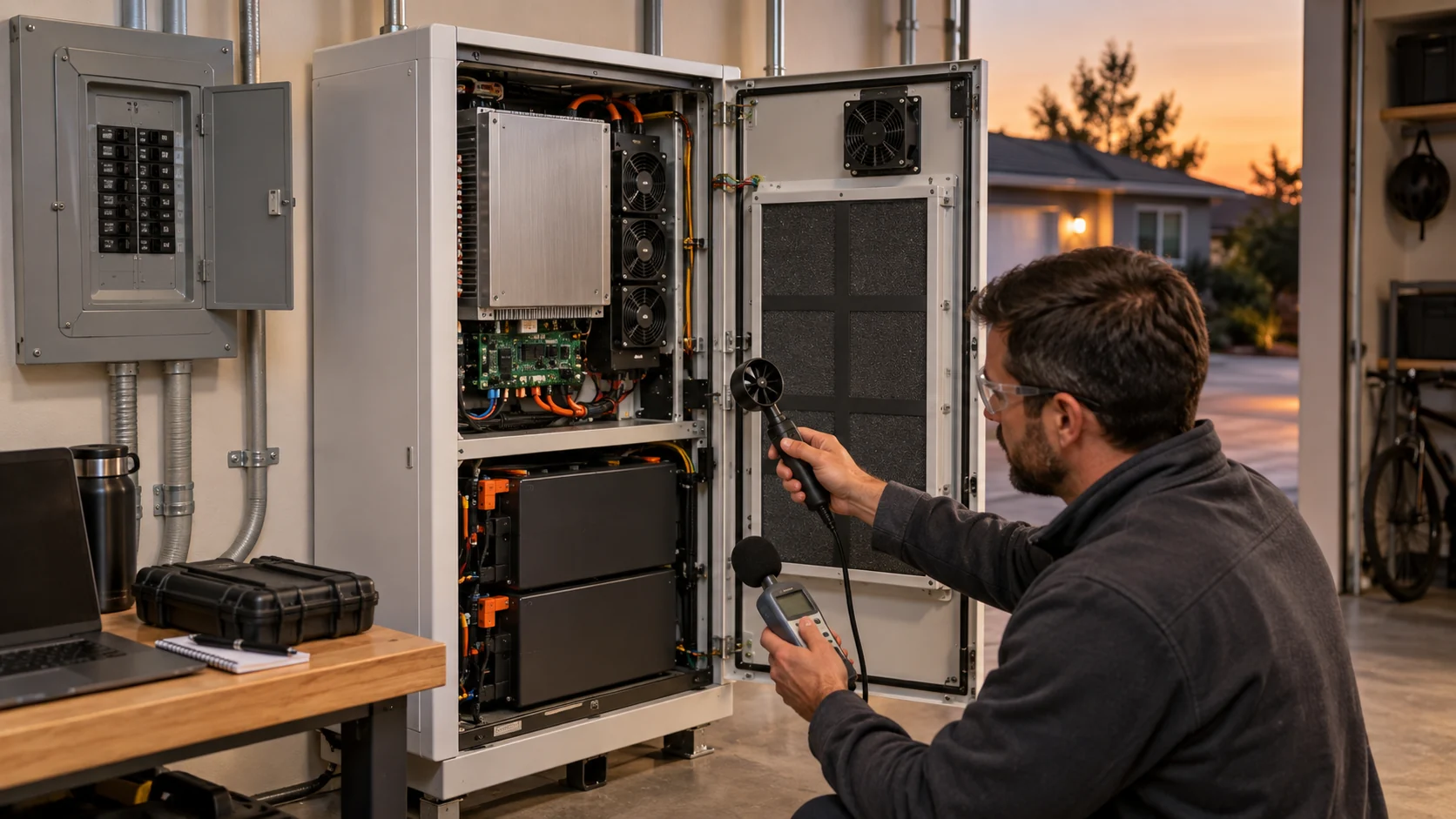
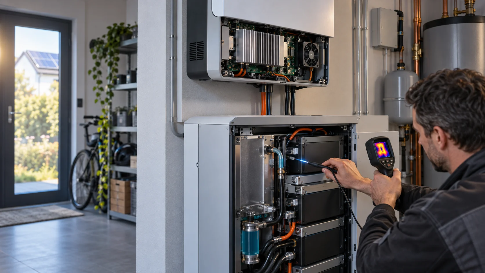
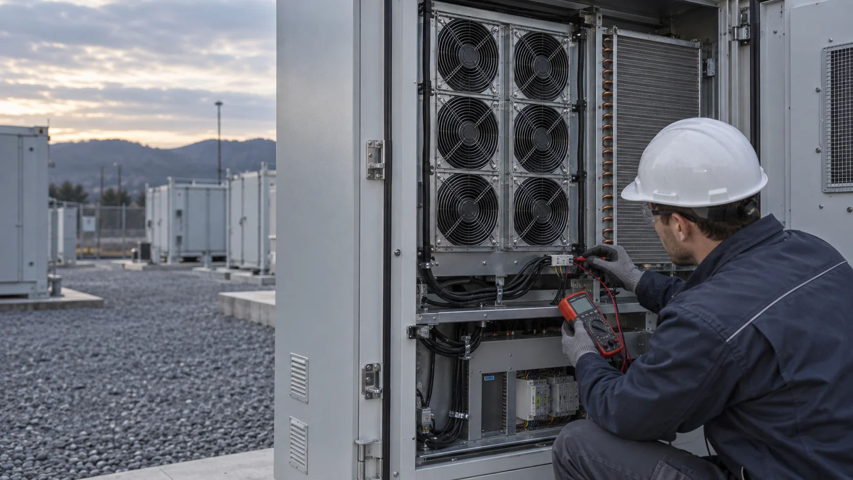
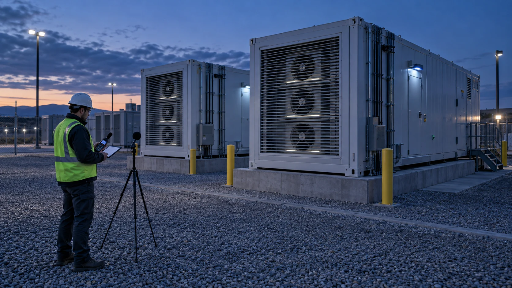
Outdoor BESS noise can come from battery and PCS cooling fans, HVAC equipment, inverters, transformers and structure borne paths. At the project boundary, the listener hears the combined site, its operating mode, its airflow path and the surrounding ground reflection together. A fan datasheet value describes one fan in a test duct; it cannot predict what six cabinets, a wall and a reflective pad do to the sound at the fence line.
Acoustic guidance for BESS planning repeatedly highlights the same missing information: when fans start, whether cooling runs at night, which mode the site sits in during the evening, and whether the control system has a night state at all. Those are controls questions, and they belong to the same engineers who own the thermal envelope.
This article separates the two kinds of loud that a fan produces, quantifies what the speed lever buys and what it spends, and gives a night control plan you can hand to a commissioning engineer with test points attached.
The Night Limit and What the Meter Must Measure
Health based night guidance is an annual average outside the bedroom window, and compliance is decided at the receptor, not at the cabinet.
The WHO night noise guideline for Europe sets the health based target at an annual average night level of 40 decibels outside, measured as Lnight,outside, with 55 decibels as an interim target where the guideline cannot be met at once. The guideline is about sleep protection at the receptor. A BESS project usually receives its number through local permitting, but the structure of the limit is the same: an average over the night at a defined receiver position, most often the nearest residence or the property line, with the site in its operating condition.
Two conversion traps waste commissioning time. First, sound power and sound pressure are different quantities: a fan datasheet may quote sound power in decibels or sound pressure at one meter, and comparing the two directly is the most common fan selection mistake in acoustic reviews. Second, distance matters in a predictable way: for a source that radiates freely, sound pressure drops about 6 decibels per doubling of distance, so a measurement position 30 meters from the fence is not the compliance position unless the permit says so.
Write the compliance position, the averaging window and the site mode into the night plan before arguing about decibel values. Those three definitions decide whether a measurement means anything.
Two Kinds of Loud: Broadband Airflow and Tonal Whine
A fan makes a whoosh and a whistle. The whoosh responds to speed; the whistle responds to geometry and electronics, and regulations punish it extra.
Broadband airflow noise rises and falls with airflow and speed. Tonal noise concentrates at specific frequencies: the blade passing tone sits at the blade count times revolutions per minute divided by 60, so a six blade impeller at 2,400 rpm puts a tone near 240 hertz; motor electronics can add a whine tied to the switching of the drive; and structure borne paths can carry pump, transformer or cabinet panel resonances into the night. A weighted meters compress what the ear hears, and a tone that looks small in a wideband number can dominate a complaint.
Assessment frameworks handle the whistle with a penalty. Under ISO 1996-2, if the level in a one third octave band exceeds both neighboring bands by a criterion that depends on frequency, the source is judged tonal and a correction, commonly 5 to 6 decibels, is added to the measured level for compliance. The practical consequence for a BESS site is sharp: a tonal fan can fail a 45 decibel limit while measuring lower than a broadband neighbor that passes.
This is why the night plan must treat the tone as its own design item. Lowering speed moves the blade passing tone down in frequency and usually shrinks it, but the tone lives at the boundary between geometry and control, and its evidence is a spectrum, not a single meter reading.
| Frequency range | Band must exceed both neighbors by | Typical correction |
|---|---|---|
| 25 to 125 Hz | 15 dB | about 5 to 6 dB added for compliance |
| 160 to 400 Hz | 8 dB | about 5 to 6 dB added for compliance |
| 500 to 10,000 Hz | 5 dB | about 5 to 6 dB added for compliance |
The Speed Lever and Its Two Currencies
Speed reduction buys decibels and spends thermal margin, and both sides of that trade have exact numbers.
For one fan in a fixed system, sound follows an approximate law: the change in sound power is about 50 times the logarithm of the speed ratio. Slow a fan to 90 percent and sound drops about 2.3 decibels; 80 percent buys 4.8; 70 percent buys 7.7; 50 percent buys about 15. The same fan laws set the price: airflow falls in direct proportion to speed, pressure falls with its square, and electrical power falls with its cube. That is why the slow setting is nearly free in energy and never free in cooling.
The quiet state therefore has a floor. It is the lowest verified fan state that still holds the agreed thermal and pressure margin for its operating mode, and the high ambient margin guide shows how to reserve that margin explicitly. A night state chosen because the number looked slow, with no measurement behind it, is a thermal incident scheduled for the first warm night of the year.
Speed is the biggest lever, but not the only one. Blade tip speed drives fan noise, which is why a larger impeller running slower at the same airflow is usually quieter than a small one running fast, and fan vendors document selections several decibels apart for identical duty. Inlet condition comes next: a clean approach into the impeller, without struts or sharp obstructions in front of the blades, removes turbulence that the ear hears as extra broadband sound. Both levers are geometry decisions made at selection time, which is exactly why the fan supplier belongs in the acoustic conversation before the frame size is frozen.
Treat the two currencies separately in the control table: for each mode, record boundary decibels, delivered airflow or pressure evidence, and component temperature headroom. The predictive maintenance signals guide lists the channels to log so the trade stays visible in operation, not only in commissioning.
| Speed | Sound change (50 log rule) | Airflow | Electrical power |
|---|---|---|---|
| 90 percent | minus 2.3 dB | 90 percent | 73 percent |
| 80 percent | minus 4.8 dB | 80 percent | 51 percent |
| 70 percent | minus 7.7 dB | 70 percent | 34 percent |
| 50 percent | minus 15 dB | 50 percent | 12.5 percent |
One Fan, Two Modes
The same fan at the same site: full speed by day, a verified quiet state at night, and both numbers on the record.
Read the two panels as a controls decision, not as two fans. At full speed the site is thermally comfortable and acoustically exposed: the blade tone crosses the penalty line, which costs 5 to 6 extra decibels in assessment. At 70 percent speed the broadband level drops, the tone shrinks below the criterion, and the margin to alarm is smaller but measured. The night state is defensible because both sides of the trade carry numbers.

Resonance Bands and Jump Settings
Some speeds are structurally loud for reasons no fan law predicts, and the control system should step over them instead of through them.
Every cabinet has structural and acoustic resonances: panel modes, louver reeds, duct organ tones. A fan speed that excites one of them can be louder than speeds above and below it, and the sound at those speeds is often more annoying because it is tonal or modulated. ASHRAE guidance on variable speed systems recommends critical frequency jump bands: the controller skips the speed range that excites the resonance and transitions through it without dwelling.
Finding the jump bands is a commissioning task, not a desk exercise. Sweep the fan speed across its range at night with a spectrum at the boundary, mark the speeds where a tone or a rumble appears, and write the excluded band into the control table with the evidence attached. The wiring and PWM validation guide covers how to prove the commanded speed equals the delivered speed, which this sweep depends on.
Add hysteresis and a response delay so a noisy sensor does not repeatedly sweep fan speed through an objectionable band during the evening. A control that hunts between two states turns a compliant site into a modulating one, and modulation attracts complaints that a steady tone would not.
Resist the reflex to fix every acoustic finding with an attenuator. A lined section or acoustic louver inserts loss, but it also inserts pressure drop at the same airflow, and that pressure drop pushes the fan back up its curve toward the speed you were trying to leave. A broadband attenuator is often strong in mid and high frequencies and weaker exactly where a blade tone sits, so it can miss the mechanism that triggered the complaint. Set the geometry and the speed plan first, measure again, and treat attenuation as the last lever with its pressure cost written next to it.
Interactive: Keep the Noise Plan Inside the Thermal Envelope
This qualitative interactive is not an acoustic prediction or a BESS safety model.
Switch between night, high load and resonance risk states to see why the speed plan needs pressure and temperature evidence beside it. The acoustic number and the thermal number move together, and the plan is the pair of them. The outdoor air path guide adds the filter loading effect: as the filter loads over months, the fan at the same command moves toward more sound at the same delivered airflow, which is why the night state needs a periodic re-verification.
Build a Night Control Plan Engineers Can Validate
Three defined states, one sweep for resonance, and a measurement at the compliance position make the plan checkable by a stranger.
Define at least three states. A cool night, light load state: the quiet setting, with its measured boundary level and its verified thermal margin. A representative operating state: the normal evening condition, which for many BESS sites is still a charging schedule, not silence. And the project worst noise case: maximum cooling demand coinciding with the acoustic compliance window, which is exactly the combination most plans forget to measure.
For each state, write three numbers: fan command or speed, boundary sound with the spectrum attached, and thermal evidence, meaning component temperatures against their limits at that state. The quiet setting is defined as the lowest verified fan state, and verification means a test, at night, cabinet closed, at the compliance position. A statement that the fans slow down at night is not a plan; a table with the numbers is.
Close with governance. Who re-verifies the quiet state after a filter change, a fan replacement or a firmware update? Which log proves the site actually ran the night state? The night plan is a control document, and it lives or dies by whether its numbers can be re-measured by someone who was not in the room when it was written.
What MEGA Tech Does for Quiet Night Operation
We build the fan around the acoustic constraint, and we give you the data to defend the quiet state.
We can do: custom DC and EC axial and backward curved centrifugal fans selected for the installed operating point at the quiet state, not just the full speed corner; blade count and speed combinations chosen so the blade passing tone falls where your spectrum can absorb it; PWM control behavior validated on the bench and on your harness, including the jump band and hysteresis logic your controller will run; and samples you can test in the real cabinet at night before volume.
We need from you: the compliance position and night limit, the operating modes with their cooling duty, the allowed quiet state speed or airflow floor with its thermal margin, the spectrum at the boundary if a prior measurement exists, voltage and control interface details, space and connector constraints, noise targets, and the lifetime assumption.
We do not supply: the acoustic assessment, the enclosure or attenuators, the controller, or the site permit. We make the fan a measured, predictable part of the night plan, and we hand you the evidence that the quiet state still cools.
Noise Problems and Their Control Levers
Match the sound you hear to the lever that moves it, and to the evidence that proves the lever worked.
The worst night in a BESS acoustic review usually has one dominant mechanism, and spending on the wrong lever wastes both money and thermal margin. Identify the mechanism first, with a spectrum rather than an opinion, and then apply the single lever that addresses it.
| Mechanism | Sound signature | Primary lever | Evidence it worked |
|---|---|---|---|
| Broadband airflow | Whoosh, tracks speed across the spectrum | Lower the quiet state speed within the thermal floor | Boundary level drop near the 50 log prediction |
| Blade passing tone | Narrow spike at blade count times rpm over 60 | Blade count or speed change that moves the tone; inlet obstructions removed | Spike below the ISO 1996-2 band criterion |
| Electronics whine | High frequency tone tracking the drive | Drive switching strategy, filtering, or a fan variant with sealed electronics | High band tone below criterion at the boundary |
| Structure borne | Rumble or panel buzz at specific speeds | Jump band around the resonance speed; stiffness or damping at the panel | Sweep shows no tone inside the operating range |
Engineer FAQ: Outdoor BESS Fan Noise
Short answers to the questions this plan raises most often.
Q: Can a fan datasheet dBA value prove a BESS boundary noise result? A: No. The installed air path, the number of sources, the operating mode and the site geometry decide the boundary level. A datasheet quotes one fan in one test configuration, and sound power versus sound pressure confusion makes the comparison worse.
Q: Does lower PWM always solve night time BESS noise? A: No. It may reduce fan speed, but it can reduce pressure and airflow out of the safe region, it can push the operating point into a resonance, and it does nothing for a transformer hum. Measure the spectrum and the thermal margin before adopting the slow setting.
Q: What night limit should the plan target? A: The number in the permit, expressed the same way. WHO guidance sets a health based target of 40 dB annual average Lnight,outside, but the compliance value and its averaging window come from the local authorization.
Q: Why did the site get louder after months of operation at the same command? A: Filter loading moves the fan toward higher pressure at the same airflow and can raise sound while cooling quietly degrades. Re-verify the night state after service, and log filter differential pressure next to sound.
Q: What is a jump band and why should the controller have one? A: A speed range that excites a structural or acoustic resonance. The controller transitions through it without dwelling, which prevents tones and rattles that no average level limit catches.
Q: How do we keep the quiet state honest over the project life? A: Re-measure it after any fan, filter or firmware change, and keep the three numbers per state on record: command, boundary level with spectrum, and thermal margin.
Questions for a Design Review
Ask these before the first warm night tests the quiet state for you.
- What is the compliance position, the averaging window, and the limit expressed the same way as the permit?
- Which site mode runs during the compliance window, and has that exact mode been measured at the boundary?
- Where is the blade passing tone of the selected fan, and does it clear the ISO 1996-2 band criterion in the quiet state?
- What are the resonance jump bands, and who proved them with a night sweep?
- What is the thermal margin of the quiet state, measured, in kelvin, against which component limit?
- What re-verifies the quiet state after a filter change, a fan swap or a firmware update?
- Does the control have hysteresis and a response delay so it cannot hunt between modes all evening?