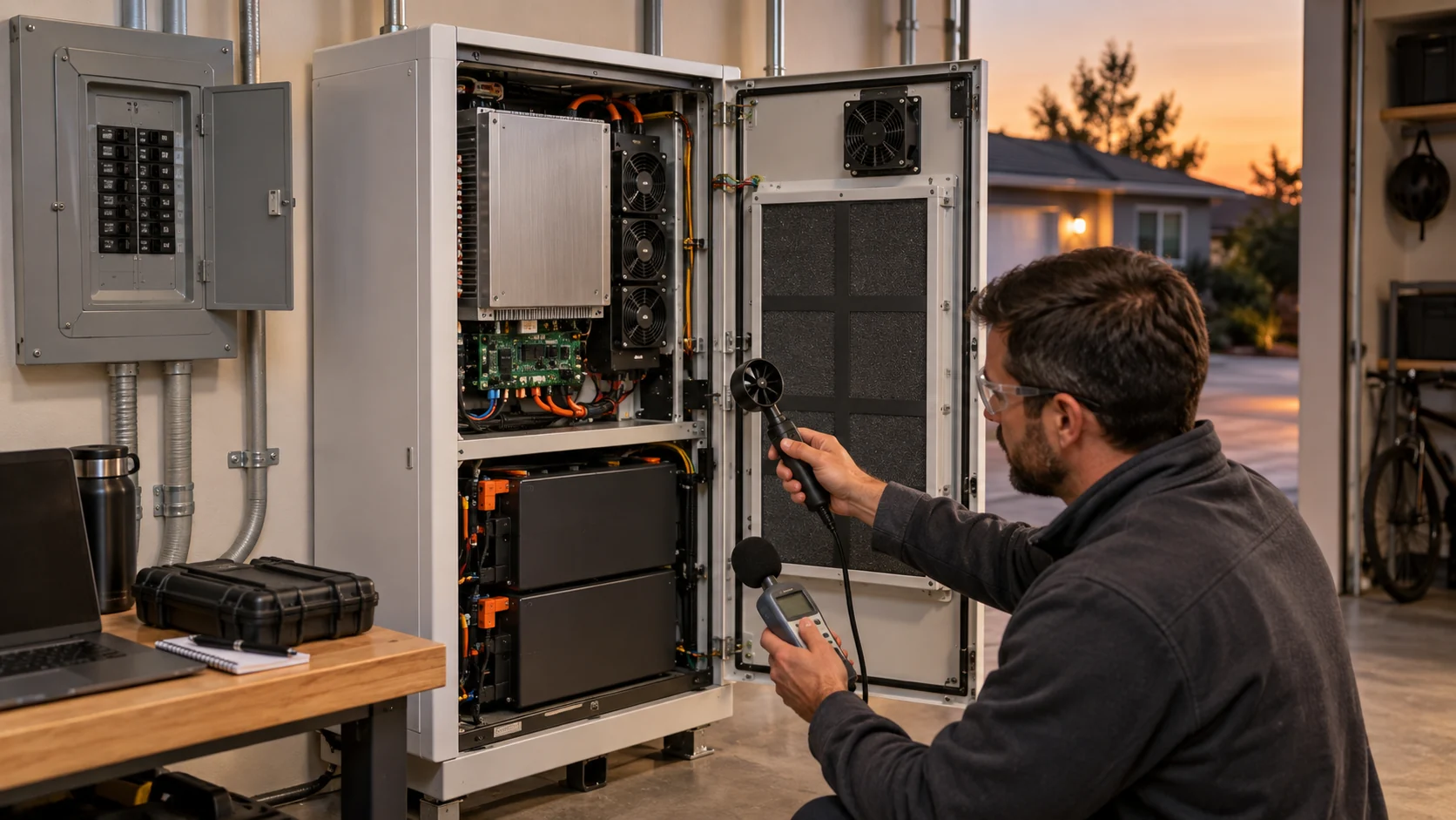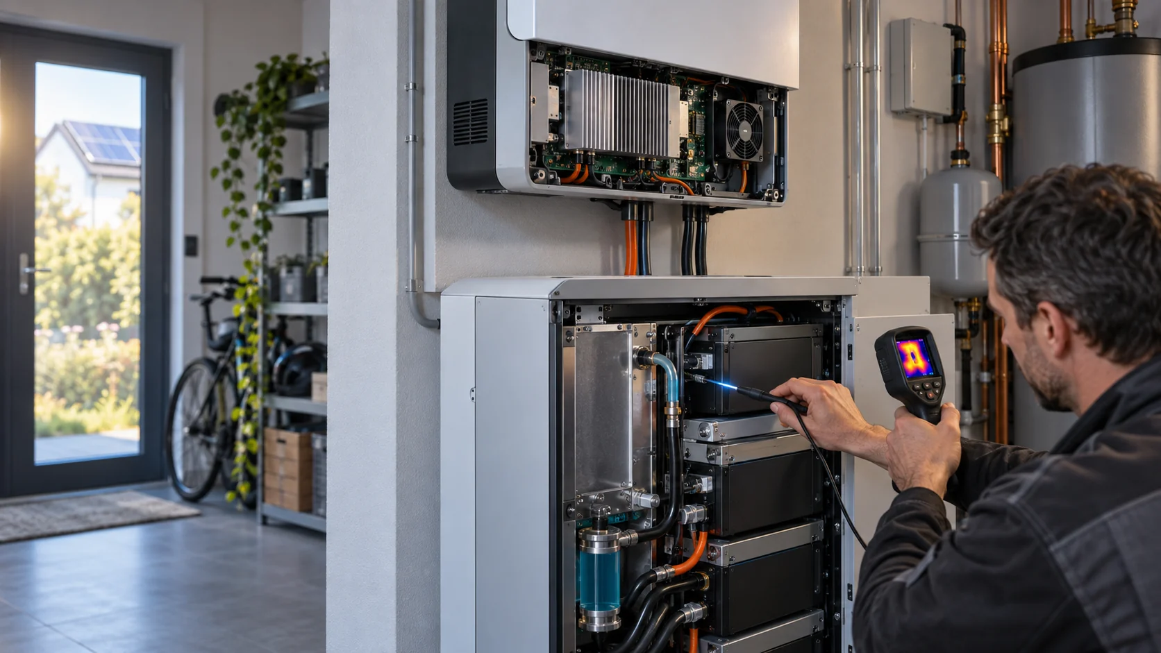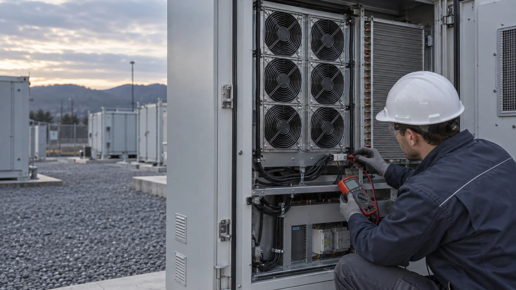
A Stable Temperature Reading Does Not Prove BESS Cooling Is Ready
At steady state, a fan, coil and controller can look healthy while the system has never faced the load change it was purchased for.
The U.S. Department of Energy describes commissioning as verifying that installed systems operate against documented requirements, not merely that they run. For a battery energy storage enclosure, that distinction lands on one question: when the power electronics step from a light load to a heavy one, does the cooling system hold the cell temperatures and the cell temperature spread inside the acceptance limits, and can it prove it on a recorded trend? A single settled reading at one load state cannot answer it, because the step itself is the event the system must survive.
This article walks the test that answers it: define acceptance before touching an instrument, run one representative power step with the air path in its service condition, capture thermal, air path and fan control evidence on one shared time base, and turn anything the step exposes into a written requirement - for the controller sequence, the air path, or the fan itself.

Write the Acceptance Test Before Selecting the Instrument
The acceptance numbers come from the project documents, and every later judgment is measured against them.
ASHRAE Handbook Chapter 44 frames the whole activity around owner project requirements: commissioning verifies and documents that performance meets defined objectives and criteria. For the cooling loop of a BESS enclosure, the criteria that matter at a power step are concrete and writable today: a maximum cell or module temperature, a maximum temperature spread across cells, a maximum filter pressure drop, a sound level at the boundary, and a behavior required from each alarm.
Across BESS projects, a commonly specified target for the cell to cell temperature spread is 5 degrees C or less within a rack, because cells at different temperatures age at different rates, and capacity follows temperature: published research on storage systems reports roughly a 1 percent capacity difference per 1 degree C between cells. Ask the cell or system supplier for their specific number, and write the measured spread into the acceptance record next to the average temperature. The average can pass while the spread quietly fails, and the spread is the number that predicts divergence.
A useful log joins thermal, air path and fan control evidence in the same time base: load current, inlet and outlet air temperatures, hottest and coldest cell readings, fan command, fan speed feedback, fan current, and filter pressure drop. When every channel is timestamped together, one event explains itself; when they live in separate exports, the commissioning argument rests on averages and memory.
| Criterion | Typical source | What the step adds beyond a steady reading |
|---|---|---|
| Hottest cell temperature | Cell supplier limit plus project margin | Shows whether the step settles below the limit or keeps climbing toward it |
| Cell to cell spread | Commonly 5 C or less within a rack | Reveals whether added load concentrates heat in the same cells |
| Filter pressure drop | Filter document, clean versus loaded states | Separates a clean-path baseline from the service state the step runs in |
| Boundary sound level | Project or permit requirement | Catches noise that only appears at the higher fan command |
| Alarm behavior | Control narrative | Proves each alarm activates on the physical event, not only in the factory test |
Interactive: Follow a BESS Cooling Power Step
Step through the states a commissioning record should cover, from the settled start to the acceptance decision.
This is a qualitative commissioning model, not a thermal prediction, control recipe or safety procedure. Use it to plan which channels to log and when.
Switch states to see why the trend matters more than a one-time fan RPM reading.
Commission the Installed Air Path, Including Its Service State
A test with the door open, the louver propped or the filter removed validates a machine that will never run on site.
Use the intended louver, guard, filter, coil, duct transition and discharge configuration. AMCA Publication 201 relates fan performance to system effect: the installed surroundings change what the fan actually delivers, so the acceptance test must run against the real path, not a bench approximation of it. A panel-open test can hide the restriction that the equipment will face in service.
Run the sequence in two passes. First record a clean baseline at a documented ambient and load state: filter fresh, louvers cycling freely, fan speeds at their default command. Then set the service state the site will actually live in - the filter at its change-out loading, the louvers under control - and execute the defined power step. The pair of records separates two different findings: a step that fails in the clean pass points at fan or control capacity, while a step that passes clean and fails loaded points at the path, and sends the investigation to the filter schedule rather than the fan.
For the pressure side of that judgment, the filter differential pressure guide gives the alarm thresholds and logging intervals that pair with this test.
Design the Step So the Response Has Time to Speak
A load change held too briefly measures nothing but the sensors.
Every thermal mass in the cabinet - cells, rack metal, coil, walls - answers a power step like a first order system: the temperature moves fast at first, then approaches the new settled value with a time constant, conventionally read at t63, the moment 63.2 percent of the total change has happened. Sensor engineering documents such as the Minco time constant paper and Ametherm application notes define t63 exactly this way, and add a rule that transfers to cabinets: let the system settle for about five time constants before calling the state stable. If the project step is held for less than a couple of time constants, the record shows only the start of the curve, and nobody can say where it would have settled.
So write the hold time into the test plan before the test: a representative load magnitude drawn from the site duty - for example the step from the overnight state to the peak charge or discharge state the interconnection study expects - held long enough to show at least the first two time constants on every logged channel, with the sampling interval short enough to catch the rise. ASHRAE Handbook Chapter 44 makes the same demand in building language: functional performance testing validates performance under varying load conditions, and trend data provides the evidence.
One more rule keeps the record honest: freeze the fan control at its normal mode during the step. The commissioning question is what the installed controller does on its own, and a technician overriding commands mid-test turns the record into a story about the technician.
What the Trend Must Contain, Channel by Channel
The evidence lives in the shape of the curves, not in their endpoints.
Read the step record for four things. First, the settling shape: each temperature channel should show the exponential approach with a believable time constant; a curve that keeps drifting past five time constants says the hold was too short or something inside the cabinet is still redistributing heat. Second, the spread: plot hottest and coldest cell temperatures on the same axis and read the gap at the settled end of the step, when the thermal field has stopped moving, because mid-step the gap exaggerates.
Third, the fan control evidence: command, speed feedback and current should track each other with no long flat spots, and the fan control logic guide lists the signal behaviors that count as healthy. Fourth, the alarm record: each alarm should carry a timestamp that matches the physical event it answers. An alarm that fires early, late or never is a finding even when every temperature stayed inside its limit.
Keep the two passes comparable: same ambient window where possible, same sampling, same channel list. The comparison is the finding engine - a filter that loaded faster than expected, a fan that lost speed between passes, a spread that grew with the seasons.
| Channel | Why it is on the same axis |
|---|---|
| Load current | Defines the moment of the step and the magnitude of the thermal event |
| Inlet and outlet air temperature | Gives the heat the air path actually removed during the step |
| Hottest and coldest cell | Yields the spread at the settled end, the number that predicts aging |
| Fan command and speed feedback | Shows whether the controller followed the step or hesitated |
| Filter pressure drop | Ties the thermal result to the service state of the path |
| Alarm log | Anchors each protection action to the physical event that caused it |
The Spread Is the Prevention Number, Not the Average
Two racks can post the same average temperature and age at completely different rates.
Cooling capacity and temperature uniformity are two separate achievements, and a cabinet can own one without the other. Total cooling answers how much heat leaves the enclosure; the spread answers whether it leaves every cell at the same rate. At a power step the spread grows first: air warms as it travels through the rack, so cells near the exhaust see warmer cooling air than cells near the inlet, and the cells buried in the middle of the rack lose heat more slowly than the ones near the walls.
Industry references for air cooled racks put typical achievable spreads an order apart: well tuned liquid cooled systems hold roughly 3 to 5 degrees C, while air cooled systems commonly land between 8 and 15 degrees C without flow guidance. Against the commonly specified 5 degree ceiling, that gap is the difference between passing and failing - and it explains why the step test measures the spread at several rack positions instead of trusting one sensor near the inlet.
When the settled spread exceeds the limit, the fix ladder starts at the cheapest rung: verify the fan speed command actually reached the value the record claims, then check for recirculation shortcuts and missing baffles, and only then consider more fan. The air bypass and dead zone guide maps the recirculation patterns that a passing average temperature can hide.
Validate Fan Redundancy as Part of the Same Test
The step is the one moment the loss of a fan is realistic, so the loss belongs inside the test window.
A power step with the array at full command is the closest the test bench ever comes to a hot afternoon at full dispatch. Schedule the redundant fan check inside that window: with the step settled, stop one fan and watch what the record shows - remaining fans accelerating, airflow holding, hottest cell drifting at a rate the log makes arguable. The fan array failure validation guide walks the full evidence set for that scenario.
Two results matter. If the remaining fans hold the temperature and the spread inside limits for the required dwell, the N plus one claim leaves the datasheet and becomes a recorded fact. If they do not, the finding has a precise address: the step magnitude, the dwell time, the fan state, and the channels that drifted first. That record is exactly what a control change or a fan change proposal needs to quote.
Do Not Skip the Moisture Sequences
Cooling is half the HVAC duty; the step test should also prove the cabinet stays dry while temperatures swing.
Every large temperature swing moves the coldest surfaces in the cabinet across the dew point of the air inside it. Coil faces, the inlet plenum and metal rails can collect condensate during or after a step, especially in humid seasons or after a cool night follows a warm day. The moisture sequence therefore belongs in the same commissioning window: run the step, then verify that the dehumidification or heating sequence recovers the surface temperatures above the dew point within the time the project allows, and that no drip path crosses electrical compartments. The condensation and dew point control guide details the sensor placement and the control logic this sequence exercises.
Record the recovery the same way as the thermal step: one time base, dew point and coldest surface on the same axis, recovery time measured to the project criterion. A cabinet that cools well but dries slowly fails its environment on a schedule nobody sees until the first corrosion findings.
What MEGA Tech Does With the Step Record
A commissioning finding becomes a fan requirement only when it is written in airflow, pressure and control terms.
MEGA Tech builds custom DC and EC cooling fans - axial and backward curved centrifugal - for enclosures like this one, and the power step record is the document our engineers work from. Bring us the trend and we translate it into a fan requirement at the operating point: airflow at the static pressure the installed path imposes, the voltage window the harness actually delivers, the control interface the cabinet uses, and the acoustic ceiling the site permits. We select by operating condition rather than by frame size, and samples are validated on the customer's real machine - the same power step, the same channels, a before and after pair of records.
To quote and build the sample we need from you: the airflow and static pressure at that airflow from the step record, the temperature and altitude reference for the site, supply voltage and its tolerance at the fan connector, the control and feedback interface including connector type, the space claim, the noise target at the boundary, and the life assumption in years or hours. We do not supply coils, liquid cooling loops, controllers, enclosure safety design or emergency ventilation - those stay with the system integrator, and our fans must prove themselves inside your architecture, not around it.
The same record rules out a false economy. Two fans with the same outline are not equivalent when one holds the settled spread at the step and the other cannot; the trend document is the evidence that keeps the replacement decision honest.
Engineer FAQ: BESS HVAC Commissioning and Power Steps
Short answers to the questions this test raises most often.
Q: Why is a steady-state BESS HVAC test not enough? A: It confirms one settled condition. It cannot show whether the system settles inside limits after a load change, how long settling takes, or whether the spread across cells stays acceptable while the load is high.
Q: Does normal fan RPM prove the required airflow? A: No. RPM confirms rotor speed, not airflow through the installed filter, coil and louvers. Pair speed feedback with pressure drop and air temperature rise on the same record.
Q: How long should the load step be held? A: Long enough to show at least the first two time constants on every channel - the settling rule of thumb is about five time constants to a stable state - and the hold time belongs in the test plan, not in the field improvisation.
Q: The average cell temperature passed. Is the test done? A: No. Read the spread between hottest and coldest cells at the settled end of the step. A 5 degree C target is common for a rack, and a passing average with a failing spread still predicts uneven aging.
Q: Should the test run with a fresh filter or a loaded one? A: Both, in two passes. The clean pass characterizes the fan and control; the loaded pass characterizes the service state. The difference between them is the filter maintenance argument.
Q: Can the alarm test wait for operations? A: No. Alarm behavior under a real power step is commissioning evidence. Every protection action should carry a timestamp that matches the physical event it answers.
Questions for a Design Review
Bring these to the meeting where the commissioning plan is approved.
1. Which document states the acceptance limits - hottest cell, spread, sound, filter pressure drop - and who signed it?
2. What load magnitude does the step use, and which study says that magnitude is representative of the site duty?
3. How long is the step held, and does that duration cover two time constants on the slowest channel?
4. Will the air path be in its service condition - filter loading, louver control, guards in place - during the step?
5. Which channels share the record time base, and at what sampling interval?
6. Where in the test window does the fan redundancy check run, and what dwell proves it?
7. What is the moisture acceptance: recovery time, dew point margin, and who owns the sequence that delivers it?