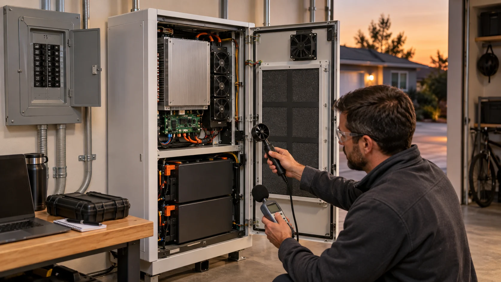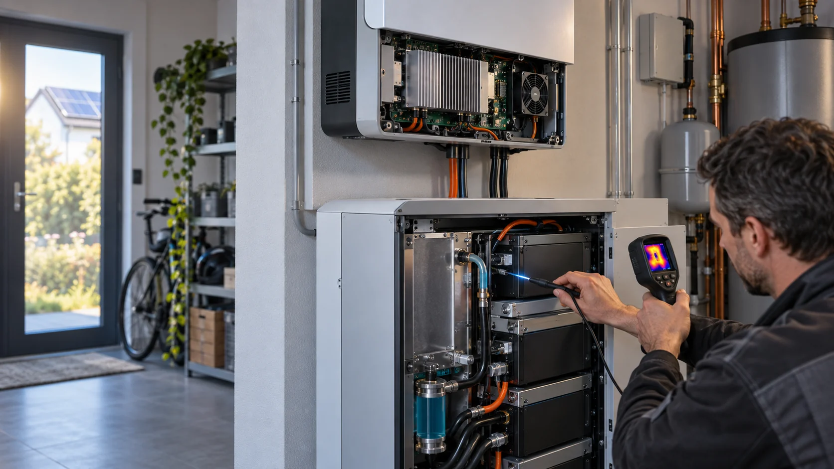
A Normal RPM Reading Does Not Prove a Healthy BESS Cooling Path
A battery cabinet can report a plausible fan speed while the command, tachometer, alarm line and delivered airflow are all being interpreted incorrectly.
BESS cooling fans are often treated as simple actuators: apply DC power, send a PWM command, read a tachometer signal and raise an alarm if the number looks wrong. In a real cabinet, the electrical interface is part of the thermal system. A wrong PWM polarity can hold the fan at a fallback speed. A wrong FG pulse-per-revolution assumption can create a false low-speed alarm. A shared ground can inject switching noise into the tachometer input. A filter or coil can then restrict airflow while the controller still reports a normal RPM.
The correct validation question is not only whether the rotor turns. It is whether the controller's command produces the intended operating point in the installed air path, whether FG and RD are decoded with the fan's actual electrical behavior, and whether those signals remain valid during converter switching, power transients and high ambient operation.
This article gives a practical commissioning sequence for normal BESS thermal cooling. It is not a universal pinout or a substitute for the exact fan specification. Four-wire PWM conventions are common, but voltage levels, pull-ups, active-low behavior, minimum speed and alarm output construction must be confirmed for the selected fan.
Separate the Four Electrical Functions Before Testing
Power, ground, speed command and feedback are not interchangeable wires.
A typical four-wire fan has a supply, a return, a tachometer or FG output and a PWM command input. The supply powers the internal motor electronics. The return is the reference for the fan and often carries the motor switching current. FG is commonly an open-collector or open-drain pulse output that needs a pull-up in the host controller. PWM is a logic-level command interpreted by the fan electronics; it is not necessarily the same as chopping the fan's supply.
The distinction between a four-wire input and a low-side switched three-wire fan matters. When the controller repeatedly interrupts the supply of a three-wire fan, the tach signal may disappear during the off portion. Analog Devices describes this as a source of erroneous readings because the tach output can float when the fan electronics are unpowered. A four-wire fan can keep its supply present while the command controls the motor drive, but that does not remove the need to verify the actual fan interface.
Create a pin table before connecting the prototype. Record pin number, wire name, reference voltage, expected logic level, pull-up location, active state and measurement point. If the fan supplier provides a drawing with a different connector orientation, preserve the supplier's pin numbering rather than copying a familiar PC color code. A connector that fits mechanically can still reverse power and signal functions.
| Function | What to confirm | How to verify |
|---|---|---|
| Supply and return | Voltage range, startup current, ripple and return-current path | Measure at the fan connector during startup and speed changes |
| PWM command | Frequency, amplitude, polarity, pull-up or open-drain requirement and minimum duty | Oscilloscope at the fan pin, not only at the controller output |
| FG / tachometer | Pulse-per-revolution definition, output type, pull-up voltage and valid low level | Measure waveform, frequency and duty at minimum and maximum speed |
| RD / alarm | Active state, open-drain behavior, reset condition and fault latency | Force the defined fault and log controller response |
| Connector and shield | Keying, pin order, cable length, shield termination and drain path | Continuity check plus EMC test with final harness |
PWM Frequency and Minimum Duty Are Fan-Specific Requirements
A controller's default PWM setting is not proof that the fan is receiving a valid command.
The PWM frequency is part of the interface contract. A common four-wire fan practice uses a high-frequency command so the control tone is moved above the audible range, and Analog Devices notes that frequencies above 20 kHz are often preferred for four-wire fan drive. Intel reference material includes a 25 kHz design target for a particular platform. Neither statement authorizes copying 25 kHz into every industrial BESS fan. The selected fan's specification controls.
Minimum duty is just as important. Some fans run at a defined minimum RPM whenever the command is non-zero below the minimum duty. Some stop at zero duty. Others have a startup boost, then settle at a lower command. If the BMS assumes 10% duty equals 10% speed, the cabinet can oscillate between a command and a stall-restart cycle. The result may be acoustic hunting, false RD alarms, unnecessary bearing stress and unstable cabinet temperature.
The first bench test should sweep the command slowly and record duty, frequency, supply current, FG frequency, RPM and airflow. Repeat the sweep while the fan is connected to the final filter, coil or guard. Mark the start threshold, stable minimum, linear region and saturation region. These points become the control limits; they should not be guessed from a generic PWM library.
Animated Signal Model: Command, Feedback and Airflow Must Agree
The moving particles show the control chain qualitatively; they are not a waveform or airflow measurement.
The signal chain has four checks. First, the PWM waveform at the fan pin must have the expected frequency, amplitude and active polarity. Second, the FG signal must have a stable frequency and valid logic level at the controller input. Third, the RD state must transition when the fan actually enters the defined fault condition, not merely when the command changes. Fourth, the fan must deliver the required airflow at the installed pressure.
A useful commissioning screen therefore shows command duty, PWM frequency, supply voltage, current, FG RPM, RD state, differential pressure and one or more thermal values on the same time axis. If only RPM is displayed, the controller can miss a blocked filter, a disconnected duct or a tach line that is pulled high by a failed input.

FG Tachometer: Count Pulses at the Right Place
The tachometer is a measurement signal, not a guarantee that the air path is open.
FG frequency is commonly converted to RPM using RPM = 60 x frequency / pulses per revolution. If a fan produces two pulses per revolution and the controller measures 80 Hz, the calculated speed is 2,400 RPM. If the controller assumes one pulse per revolution, it will report 4,800 RPM and may mask a real fault. If it assumes two pulses while the replacement fan provides a different output, the alarm threshold moves in the opposite direction.
Measure the signal at the fan connector first, then at the controller input. A difference between the two locations points to cable capacitance, pull-up selection, common-mode noise, connector resistance or a ground reference problem. Check the low-level voltage, high-level voltage, rise time and duty ratio at minimum and maximum speed. A frequency counter alone can show a plausible number while the waveform has slow edges that fail the controller's input threshold during a noisy converter state.
The installed fan array also changes the interpretation. If several fans share one tach line, confirm whether the signal is isolated, multiplexed or intentionally combined. Never parallel open-collector outputs without checking the resulting pull-up current and fault behavior. For N+1 designs, the controller must identify which module stopped; one combined pulse train can hide a missing fan.
RD Alarm: Define the Fault and the Response Time
An RD line is only useful when the project defines what failure it detects and what the BMS must do next.
RD may represent rotor lock, fan fault, low-speed condition or an internal protection state depending on the product. It is not safe to assume that every alarm output means the same thing across suppliers. Ask whether RD asserts during startup, during a deliberately commanded stop, after a thermal protection event, or only after the motor fails to commutate. Record the active level and the reset condition.
The BMS response should be written as a state transition. For example: if RD remains active for a defined debounce interval while the fan command is above its startup threshold, log a fan fault, switch to the redundancy state and raise the service alarm. The exact interval is a system decision; the test must show that it is longer than normal startup but shorter than the allowed thermal response time.
Test the response with a controlled fault. Disconnect the command, interrupt the supply in a safe test fixture, block the rotor only if the supplier permits that method, or use the fan's defined diagnostic interface. Do not create an uncontrolled overcurrent or mechanical hazard inside a live battery cabinet. The evidence should include fault injection time, RD transition time, BMS decision, surviving fan command and component temperature.
| Test case | Expected observation | Evidence to save |
|---|---|---|
| PWM wire open | Fan follows the specified fallback or safe state | Fan pin waveform, RPM, current and BMS alarm |
| FG wire open | Controller detects missing feedback without confusing it with a stopped fan | Fan-side FG, controller-side FG and alarm latency |
| RD active at startup | Startup grace period prevents a false trip, then the defined alarm appears if the fault persists | Time-stamped command, RD and BMS state |
| Filter pressure high | Fan may remain at normal RPM while airflow falls; pressure and thermal channels reveal the restriction | Pressure, airflow and temperature trend |
| Fan module power loss | Surviving array and controller follow the documented redundancy response | Module identity, remaining airflow and thermal response |
EMC and Grounding: The Control Harness Is Part of the Cooling Design
Many so-called fan faults are signal-integrity faults created by the shared DC bus, cable routing or return-current impedance.
A brushless fan commutates current internally, and a converter cabinet adds its own switching edges. Those currents can couple into PWM and FG lines through common impedance, capacitive coupling or radiated fields. The symptom can be a PWM duty that looks unstable, an FG pulse with extra edges, a false RD transition or a controller reset when the power stage changes state.
Start with the return path. Keep the high-current fan return from sharing a narrow PCB trace with a sensitive tachometer reference when the architecture permits a cleaner star or controlled return. Route PWM and FG as signal conductors with a defined reference. Keep the harness away from high dV/dt switching nodes and busbar edges. If a shield is used, specify where it is terminated and verify that the shield does not become an unintended motor-current return.
Use the final cable length, connector and cabinet routing in EMC validation. A short bench jumper can pass while the production harness fails. Capture the PWM and FG waveforms during inverter switching, contactor operation, fan startup and a rapid load step. The acceptance criterion should be stated as a valid logic waveform and correct BMS state, not merely that the cabinet remains powered.
A BESS Commissioning Example: The Fan Was Not the First Fault
A useful case does not end with replacing the fan; it proves which part of the control chain failed.
Consider an anonymized outdoor BESS cabinet using 24 V fans with PWM command and FG feedback. During converter power steps, the controller logged short low-RPM events and occasionally switched to a backup command. The fan passed a bench test at steady state. The first assumption was a weak replacement fan, but the installed pressure and the fan-side speed were both within the expected range.
The team then measured the four signals at the fan connector and at the BMS input. The PWM frequency was correct, but the FG waveform at the controller had extra edges during the converter transition. The cable shared a return path with a high-current switching branch, and the pull-up was placed on a controller board several meters away. After the harness return and signal reference were revised, the controller's calculated RPM became stable. A separate filter-pressure test then showed a genuine airflow reduction at the service threshold, which was handled by the pressure alarm rather than by changing the tachometer threshold.
The lesson is not that one grounding arrangement is universal. The lesson is that fan selection, signal integrity and installed pressure must be tested as separate hypotheses. A new fan can hide an interface problem for a short time, but it cannot correct a controller that is counting the wrong edges.
A Repeatable EMC and Control Acceptance Sequence
The fastest way to find a control fault is to test one interface boundary at a time, then repeat the same checks under the real power-stage disturbance.
Start with the fan disconnected from the battery cabinet but connected to the intended controller and harness. Verify the supply at the fan connector during startup, steady speed and command changes. Check for overshoot, dip and ripple rather than recording only the nominal 24 V or 48 V label. A fan that starts on a laboratory supply can fail on a long cabinet harness when the supply impedance and contactor path are different.
Next, probe the PWM pin relative to the fan signal reference. Record frequency, high and low levels, polarity, duty command and the actual waveform at the lowest stable speed, the rated operating point and full command. Then measure FG at the same reference. If the waveform is clean at the fan but distorted at the BMS, the fan is not the first component to replace; investigate the harness, pull-up, return path and input protection.
Repeat the test while the converter changes state. Use a defined step such as 25% to 75% fan command, a representative inverter load step, contactor close and the maximum normal PWM command. Save a synchronized trace of PWM, FG, RD, supply voltage and current. The engineering pass criterion should state the maximum acceptable false edge, alarm latency and recovery behavior, not simply that the operator did not see an alarm.
Finally, connect the installed air path and measure pressure and airflow at the same control states. A signal test without air-path validation can approve a fan that is electrically perfect but thermally undersized. Conversely, an airflow test without signal validation can approve a system that will create a false alarm when the power converter starts. The two tests belong in one commissioning record but remain separate acceptance lines.
For production release, freeze the interface details in the BOM and drawing: fan part number or approved family, pinout, connector key, cable length, PWM source impedance, pull-up value, FG pulse definition, RD active state, minimum command, startup timer and the replacement test method. When these fields are missing, a later cost-down replacement can appear mechanically compatible while silently changing the feedback protocol or EMC behavior.
Keep the oscilloscope screenshots with the thermal report. A future engineer can then compare a suspicious alarm with the original waveform instead of relying on a verbal description such as the fan sometimes drops RPM. This record also makes supplier communication faster: the supplier can see whether the fault begins at the fan pin, travels along the harness, or appears only after the controller interprets the signal. Label every trace with the voltage reference, probe location, time scale, ambient condition and fan state; otherwise a technically correct screenshot may be impossible to reproduce. Include the serial or sample revision so a later replacement is compared against the same electrical construction. Retain the tested sample revision and harness length with the release record, because a pin-compatible change can still alter edge shape, startup current or feedback behavior today at final release. A signed acceptance record is especially valuable when the project later compares a lower-cost replacement; it preserves the electrical and thermal baseline together, so the purchasing decision is made against evidence rather than a nominal speed or connector match.
| Step | Measurement boundary | Release evidence |
|---|---|---|
| 1. Power-up | Supply and return at the fan connector | Startup voltage, current peak, settling time and fan start result |
| 2. Command | PWM at controller and fan pins | Frequency, amplitude, polarity, duty and minimum stable command |
| 3. Feedback | FG and RD at fan and BMS inputs | Pulse shape, pulses per revolution, active state and alarm latency |
| 4. Disturbance | Converter load step, contactor and harness in final routing | No false alarm, reset or invalid tach count |
| 5. Thermal duty | Installed filter, coil or heat sink at clean and service states | Airflow, pressure, temperatures and control-state trace |
| 6. Production repeat | Approved connector, cable and replacement sample | BOM, drawing, test limits and retained waveform record |
What MEGA Tech Can Validate With You
We help convert the electrical interface and installed air path into a sample that the BMS team can qualify.
We can provide custom DC axial fans, compact blowers and backward-curved centrifugal fans with the voltage, connector, PWM, FG and RD behavior defined for the application. We can review the required operating point behind the filter, louver, heat sink or coil; check startup and minimum-speed behavior; support harness and signal checks; and provide samples for validation in the customer's BESS cabinet. Replacement review is based on the required operating condition, not on outline size or a familiar part number alone.
Send the fan model or drawing, supply voltage and tolerance, PWM frequency and polarity, minimum and maximum duty, FG pulses per revolution, RD active state, pull-up voltage, connector, cable length, grounding arrangement, required airflow and static pressure, clean and loaded filter conditions, ambient and altitude, noise limit, quantity and life assumption. If the fan is in an array, show whether tach signals are individual or combined.
We do not supply the BMS safety logic, the inverter EMC compliance program, the cabinet, filter, liquid loop or emergency ventilation strategy unless a separate verified scope says otherwise. Our role is to make the fan interface and normal cooling duty concrete, measurable and sample-testable.
Engineer FAQ: BESS Fan PWM, FG, RD and EMC
Short answers for the electrical, thermal and procurement review.
Q: Can I use 25 kHz PWM for every BESS fan? A: No. It is a reference value used by some platforms. Confirm the selected fan's allowed frequency, amplitude, polarity and input circuit.
Q: Does normal FG prove normal airflow? A: No. FG proves a rotor-related signal. A blocked filter, bypass path or disconnected duct can reduce delivered airflow while RPM remains plausible.
Q: Why is the tachometer wrong only during inverter switching? A: Common return impedance, signal coupling, poor pull-up placement or cable routing can add edges or distort the logic level. Measure at both ends of the final harness.
Q: Are RD and locked-rotor outputs identical? A: Not necessarily. Confirm the fan's fault definition, active level, debounce behavior and reset condition.
Q: Should I parallel several FG outputs? A: Only if the output construction and pull-up current are explicitly designed for it. Individual fan identity is preferable for redundancy diagnostics.
Q: What should be measured during a fan sample test? A: PWM at the fan, supply voltage, current, FG waveform and calculated RPM, RD state, installed pressure, airflow and component temperature across clean, loaded and high-ambient states.
Questions for a Design Review
Use these questions before releasing the BESS fan harness and controller interface.
- What are the exact PWM frequency, amplitude, polarity and minimum-duty rules for the selected fan?
- How many FG pulses per revolution does the fan produce, and is the output open collector or another interface?
- What does RD detect, what is its active state, and how long may the BMS wait before escalating?
- Where is the pull-up for FG and RD, and what voltage and current does the fan output see?
- Are PWM, FG and RD measured at the fan connector as well as at the controller input?
- Does the final harness pass converter switching, contactor operation and load-step tests without false edges?
- What pressure, airflow and thermal evidence proves the fan is doing useful work in the installed cabinet?
- What exact information will be sent to the supplier for a custom sample: voltage, control, connector, cable, operating point, environment, noise, quantity and life?