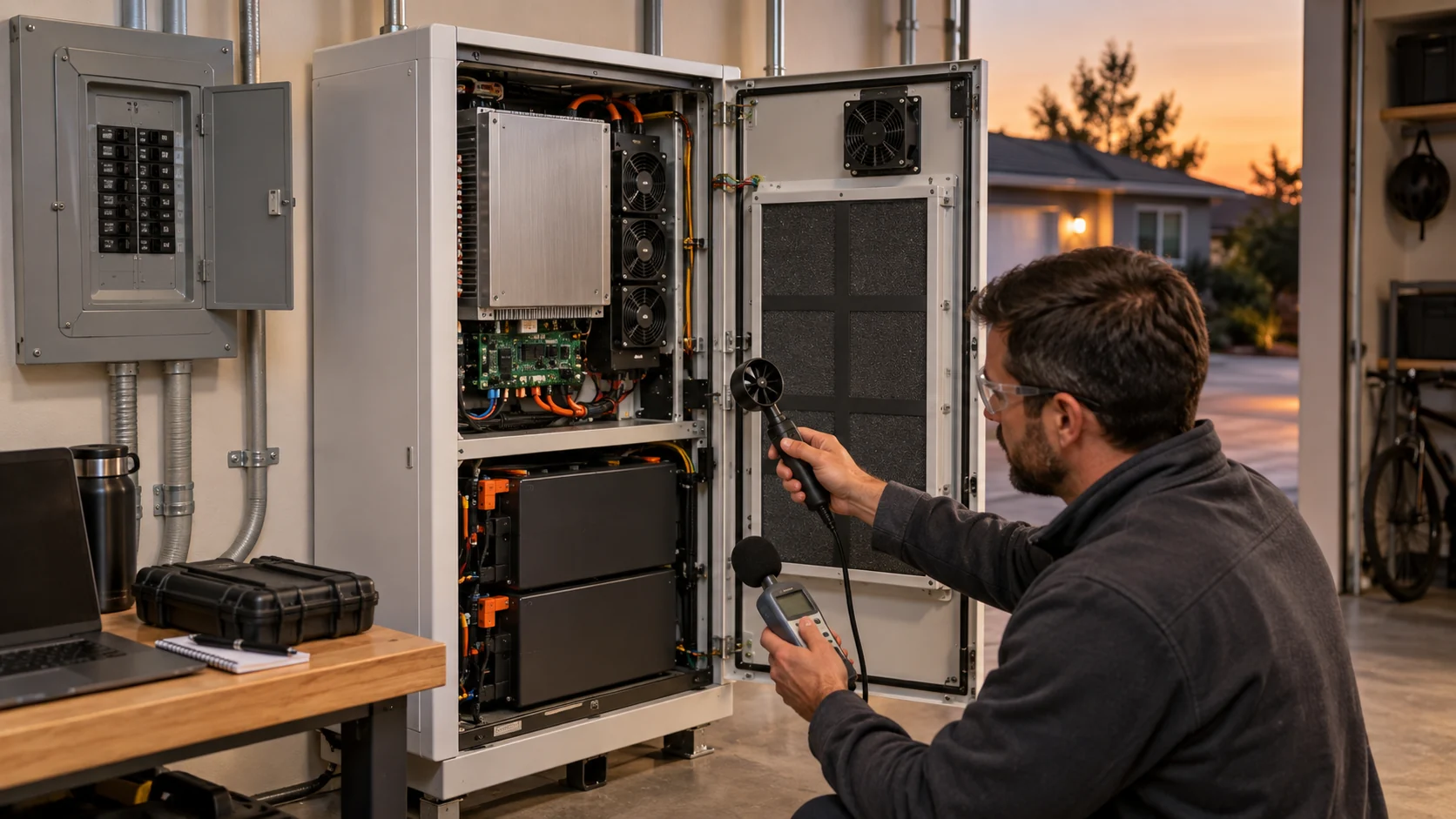
Do Not Treat a Lower PWM Command as a BESS Energy Result
A slower fan spends fewer watts on its own branch, but the auxiliary-power claim lives or dies at the meter boundary and at the hottest cell.
Auxiliary systems in a battery energy storage project include the thermal management package, controls and communications, lighting, and other balance of system loads. Auxiliary load levels vary widely by design and climate; one widely cited industry reference puts them between roughly 0.5 and 5 percent of rated system power, and market rules differ on how they are metered and settled - in ERCOT the auxiliary load is metered separately from battery charging and billed at retail, while in CAISO only the idle share follows that rule. A percentage quoted without its boundary is not a number an engineer can use.
So the engineering question is not whether a PWM command can be reduced. It is whether the installed cooling path still holds the agreed temperature and spread across the loads, ambients and filter states the site will actually see - and whether the watts saved are measured where everyone agrees the measurement lives. This article walks both halves: define the meter boundary and the operating states first, then use fan laws as a screening estimate, then prove the control setting on the installed system with the same trend discipline a power step test demands.

Define the Meter Boundary Before You Claim a Saving
Three records, three boundaries - and no number leaves its own boundary.
Create separate records for the fan branch, the thermal management package and any project level auxiliary meter. The fan branch record covers fan current, voltage, command and speed feedback; the package record adds coils, pumps, heaters and their controls; the project meter adds lighting, communications and safety systems. A saving found on the fan branch does not automatically appear on the package meter, because the controller may spend the saving elsewhere - heaters recovering from a cold night, for example - and a project meter can swallow a fan saving entirely.
For a screening calculation, energy is power multiplied by time. If a measured fan branch changes from 180 W to 120 W for the eight hours a day the economy state is active, the screening saving is 60 W times 8 h, or about 0.48 kWh per cabinet day. That number becomes contract language only when the record states which loads it includes, which states produced it, and how many hours each state holds. One number without a boundary invites two readings and a dispute.
Buyer guides for commercial storage make the same demand from the commercial side: request measured consumption by subsystem, under a stated duty cycle and boundary, rather than accepting a universal percentage - because suppliers quote ideal conditions while high ambient sites and real duty cycles can push the auxiliary share far higher than the datasheet suggests.
| Record | Loads inside | What a saving there proves |
|---|---|---|
| Fan branch | Cooling fans only: current, command, speed feedback | The fan spends fewer watts at the tested states |
| Thermal package | Fans plus coils, pumps, heaters and their controller | The cooling function spends fewer watts while holding temperature |
| Project auxiliary meter | Everything auxiliary: thermal package, lighting, controls, safety | The site buys less energy per cycle than before |
Interactive: Check the Auxiliary-Energy and Thermal-Margin Trade
Step through operating states and watch the two numbers move against each other.
This qualitative aid does not calculate battery temperature, HVAC efficiency or an exact fan curve. It structures the conversation between the energy target and the thermal margin.
Switch operating states to see why a low command under clean conditions cannot be approved as a universal energy setting.
Use Fan Laws as a Screening Tool, Not a Whole-System Promise
The cube law is real, but it applies to the fan under stated similarity conditions - not automatically to the meter.
AMCA fan law material relates airflow, pressure and power to speed when similarity holds: airflow follows speed, pressure follows speed squared, and power follows speed cubed for the same fan at the same density. At 70 percent speed the cube law gives about 34 percent of the reference power - on a 180 W branch, roughly 62 W. That arithmetic is the screening estimate that decides whether an economy state is worth testing at all.
The installed result can differ for three recorded reasons. First, the operating point moves along the system curve, not along the fan curve alone, so the pressure the fan sees changes with flow. Second, motor and drive losses do not scale with the cube; an EC fan document such as an ebm-papst 48 V unit states efficiency and input power at each operating point, and those tables beat any scaling law. Third, the control system may respond to the slower fan by running other equipment - heaters, a second stage - that spends the saving back.
So write the projection as a range with the law named: a screening estimate from the cube law, to be confirmed on the fan branch meter across the tested states. When the confirmed number differs from the screening number, the difference itself is a finding about the installed system.
Tune the Control Against the Installed Service Range
An economy state is an operating point, and an operating point has to survive the states the site lives in.
Build the tuning plan around representative states: the relevant charge or discharge loads, the local intake temperature range, and both filter states - fresh and near change out. Start with a documented baseline at full command, then step the command down in stages, holding each stage long enough to read the settled hottest cell and spread, with the same time base discipline as any acceptance test. DOE commissioning guidance frames this exactly: verify installed performance against documented requirements, with trend data as evidence.
The efficient setting is the lowest verified control state that still meets the agreed duty across those states - not the slowest number that looked safe on a mild spring morning. Where the states interact with sound, the night noise guide shows how a quiet state and an economy state can share one verified setting, and where they must differ.
Close the loop with the controller: command, feedback and current should agree at every stage, per the fan control logic guide. A stage where current drops less than the cube law predicts is a stage where the fan is riding a different operating point than assumed - a loaded filter, a partially blocked intake, or a control loop hunting.
Filter Loading Is the Silent Variable in the Energy Record
The same command buys less airflow as the filter loads, and the energy record must say which state it was taken in.
AMCA Publication 201 relates fan performance to system effect: as the filter loads, the system curve steepens, the operating point climbs to higher pressure and lower flow, and the watts per delivered unit of airflow rise. A fan branch that holds 120 W in the fresh filter state may hold 118 W in the loaded state while delivering meaningfully less airflow - and an energy record that omits the filter state will read that as stability when it is actually drift.
So pair every energy measurement with the filter pressure drop on the same time base. The pair turns the record into a statement the maintenance plan can use: the economy state holds its margin up to a stated pressure drop, beyond which the site either changes the filter or returns to full command. The filter differential pressure guide supplies the thresholds and the logging interval.
This pairing also protects the thermal verdict. A setting proved only on fresh filters borrows margin that belongs to the loaded weeks of the year; the loaded filter pass is what makes the setting honest.
EC Input Tables Beat Scaling Laws at Partial Load
The screening law estimates; the fan document states.
For the fan itself, the honest source at partial load is the manufacturer input table, not the cube. An EC fan document lists input power, speed and airflow at each operating point, because the electronics add a loss floor that does not shrink with the cube: at low commands a growing share of the input goes to the control electronics rather than the air. Reading the table at the candidate states replaces the screening estimate with stated values, and often shows the economy state saving less than the cube promised - still worthwhile, just smaller.
The table also protects the other side of the trade. Two fans with similar full speed ratings can differ sharply at 60 or 70 percent command, which is exactly where an economy state lives. Choosing the fan that holds efficiency across the partial load range is a selection decision the energy record makes visible, and it is one reason a frame size match is not a fan match.
Auxiliary Watts Follow the Site Into an Outage
The same watts that erode the round trip also drain the backup clock.
When the grid connection is lost, part of the auxiliary load may be required to keep running: controls and communications always, and on many projects the thermal management too, either by supplier requirement or by fire code. NFPA 855, as summarized in project design guidance, requires a minimum of two hours of standby power for gas detection and concentration reduction systems, and some suppliers mandate uninterrupted power to thermal management to protect the cells. Every watt the cooling branch spends in that window is a watt that does not reach the facility loads the backup was sized for.
So the economy state has a second audience beyond the energy bill: the backup duration calculation. A verified setting that halves the fan branch watts in the standby state extends what the same battery can support, and the record should capture fan watts in the standby state explicitly, because that state has its own duration requirement and its own meter reading. Buyer guides make the same point commercially: auxiliaries belong in the system power balance, in backup duration, and in the project cost model - not only in the efficiency table.
What the Verified Setting Buys the Project
A proven economy state is bankable; a hopeful one is a thermal incident on a schedule.
When the record shows the fan branch watts, the thermal margin and the filter state on one time base across the tested states, the economy setting becomes contract language: the site can state its auxiliary energy per cycle with a boundary, and the operations team knows the filter pressure drop at which the setting must be revisited. That is the difference between a saving that survives an audit and one that evaporates at the first hot week.
If the verified setting cannot reach the energy target, the record says exactly where it fell short - which stage, which state, which channel drifted first. The high ambient margin guide and the power step commissioning guide carry that evidence into the next fan decision.
What MEGA Tech Does With the Energy Record
A fan requirement written in watts, pressure and control terms is one our engineers can quote and build against.
MEGA Tech builds custom DC and EC cooling fans - axial and backward curved centrifugal - for enclosures like this one, and the auxiliary energy record is the document we work from. Bring us the verified states and we translate them into a fan requirement at the operating point: airflow at the static pressure the installed path imposes in the loaded state, the input power ceiling per state, the voltage window the harness actually delivers, and the control interface the cabinet uses. We select by operating condition rather than by frame size, and samples are validated on the customer's real machine - the same states, the same meter boundary, a before and after pair of records.
To quote and build the sample we need from you: the airflow and static pressure at that airflow from the record, the temperature and altitude reference for the site, supply voltage and its tolerance at the fan connector, the control and feedback interface including connector type, the space claim, the noise target at the boundary, and the life assumption in years or hours. We do not supply coils, liquid cooling loops, controllers, enclosure safety design or emergency ventilation - those stay with the system integrator, and our fans must prove themselves inside your architecture, not around it.
The same record keeps the replacement honest: two fans with the same outline are not equivalent when one delivers the airflow at the stated watts and the other spends the saving back in losses.
Engineer FAQ: BESS Auxiliary Power and Fan Control
Short answers to the questions this record raises most often.
Q: Does a lower PWM duty prove lower BESS auxiliary energy? A: No. It can show a lower command and possibly lower fan branch watts. The saving is proven when the meter boundary, the operating states and the duration are recorded, and the thermal margin still holds at the loaded filter state.
Q: Can I apply the cube law directly to measured HVAC energy? A: No. Fan laws are a screening relationship for the fan under stated similarity conditions. Motor losses, the moving operating point and other equipment in the package all break the scaling.
Q: Which number goes into the project financial model? A: The project auxiliary meter number, per cycle, with its boundary and duty cycle stated. Fan branch numbers support it; they do not replace it.
Q: How often must the economy setting be re-verified? A: Whenever the path changes in a way the record tracks: after filter changes at minimum, and after any control or hardware change. The filter pressure drop threshold in the record triggers the check in operation.
Q: Do EC fans remove the need for this testing? A: No. An EC fan gives you accurate input power tables per operating point, which makes the screening better. The installed verification still decides.
Q: Can the same setting serve the night noise target and the energy target? A: Sometimes. Both are control states that must hold their own acceptance criteria - sound at the boundary, temperature and spread in the rack. When one state satisfies both records, one setting serves both; when it does not, keep two states.
Questions for a Design Review
Bring these to the meeting where the auxiliary energy target is approved.
1. Which meter boundary does each quoted auxiliary number use, and who signs that boundary?
2. What duty cycle and ambient produced the projection, and which study says they represent the site?
3. Which fan states were tested, and does the record include the loaded filter pass?
4. What filter pressure drop ends the economy state, and which channel watches it?
5. Where does the thermal margin sit at the settled end of each tested state, against which limit?
6. Do command, speed feedback and current agree at every stage of the tuning record?
7. Who owns the re-verification trigger in operation, and is it written into the maintenance plan?