Start with the cabinet heat load, not the fan size
A BESS cooling fan is selected against a heat load, an allowable temperature rise and a pressure path. A 120 mm outline is only a mechanical starting point.
The first design question is how much heat the air path must remove during the relevant operating state. Converter loss, battery auxiliary power, contactors, pumps and control electronics can all contribute. The fan selection should use the worst credible sustained state, not only the average daily energy figure. Record whether the value is a cabinet load, a room load or a heat exchanger load before putting it into an airflow calculation.
For a first estimate, use Q = W / (rho x cp x delta-T). W is the heat carried by the air, rho is the air density basis, cp is the specific heat and delta-T is the allowed air temperature rise. As an illustrative calculation, 2,000 W at 1.20 kg/m3, 1,005 J/(kg K) and a 10 K rise requires about 0.166 m3/s, or 352 CFM. This is a heat-balance estimate, not a fan guarantee. Filters, grilles, modules, bends and leakage still move the installed operating point.
Write the assumptions beside the result. A design at 50 °C ambient and 2,000 m altitude has a different density basis from a sea-level room test. If the enclosure is sealed, the fan may be moving air through an internal loop rather than exchanging cabinet air with the room. If a liquid loop or a dry cooler is involved, state exactly which air-side heat the fan is responsible for. That prevents a normal cooling fan from being assigned an emergency or fire-safety function it was never selected to perform.
Build a pressure budget for the complete air path
A BESS cabinet fan has to move the required airflow through the complete path, including the parts that are easy to omit from a spreadsheet.
List every restriction between the fan inlet and outlet: intake grille, filter, louver, battery module gap, heat exchanger, cable obstruction, bend, outlet grille and any backdraft or rain protection. Use the supplier curve for the clean filter and obtain a loaded-filter pressure value from the filter supplier or from a measured test. A pressure budget with only the fan and the battery module is not a pressure budget for the cabinet.
The pressure losses do not always add as independent constant numbers. A filter loss generally rises with velocity and loading; a grille can be sensitive to free area; a narrow module passage can change its loss when the flow distribution shifts. Use the pressure at the required airflow for each item, then sum the losses on the same pressure basis. If the fan is drawing through a filter, make sure the pressure sign and measurement locations are defined consistently.
The system curve and fan curve meet at the installed operating point. A catalogue maximum airflow is the zero-pressure endpoint and a maximum pressure value is the zero-flow endpoint. Neither number alone proves that the cabinet will receive the required airflow. This is why a compact, high-speed fan can be a better starting point than a larger low-pressure fan in one cabinet, while the opposite is true in another.

| Air-path item | Pressure at target airflow | State to record | Validation method |
|---|---|---|---|
| Intake grille | Measure or supplier curve | Clean and wet | Pressure taps across grille |
| Filter | Clean plus loaded value | Dust loading basis | Differential-pressure test |
| Battery module path | Calculate or measure | Worst rack path | Traverse or pressure taps |
| Outlet path | Measure or supplier curve | Louver position | Cabinet airflow test |
| Total system | Sum at target airflow | Design and fault state | Fan/system curve check |
Clean-filter selection is not dirty-filter validation
The filter condition can move the operating point enough to create a thermal problem even when the fan starts normally.
A clean filter is useful for commissioning, but it is not the only condition that matters. As dust accumulates, pressure loss rises and airflow falls along the fan curve. The cabinet may still show a plausible fan speed while the cells or power electronics receive less air. A pressure switch or differential-pressure sensor can provide an early warning, but it must be tied to a defined measurement location and a response threshold.
Use at least two acceptance states: clean filter and the specified loaded-filter condition. At both states, record fan voltage, current, command, speed, inlet pressure, outlet pressure, airflow and the temperature at the protected component. If the cabinet has several parallel paths, also check the worst path rather than relying on the average outlet temperature. A mean temperature can hide a local hotspot behind a blocked or poorly sealed section.
The control strategy should have a clear response. It may increase speed when the filter differential pressure rises, raise an alarm before the thermal limit is reached, or schedule service based on a measured trend. Do not call this emergency ventilation. Normal thermal control, smoke extraction and fire-safety ventilation are separate design functions with separate requirements and owners.
Check airflow distribution across the battery modules
Total cabinet airflow can look healthy while one branch receives too little air.
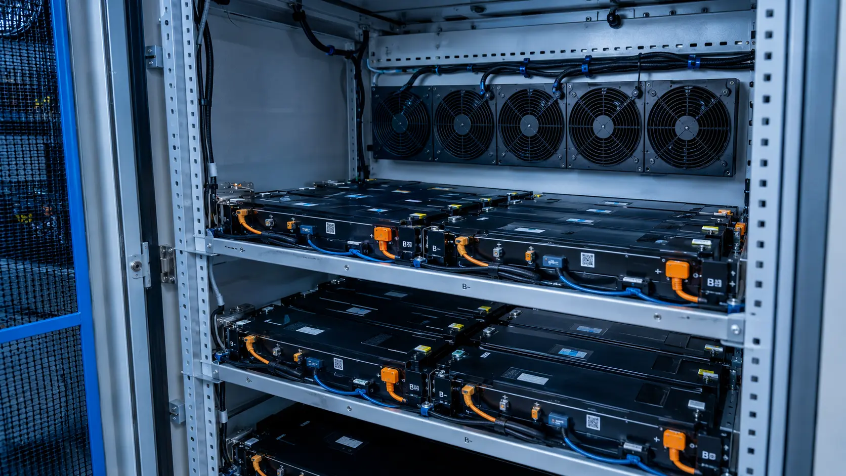
A fan, filter and outlet can pass the total airflow target while the internal arrangement creates bypass, recirculation or a dead zone. Cable trays, busbars and module frames change the local resistance. Sealing gaps around a filter or service panel can also create a low-resistance bypass that steals flow from the cells. The right check is therefore not only total CFM; it is the distribution at the locations that set the thermal limit.
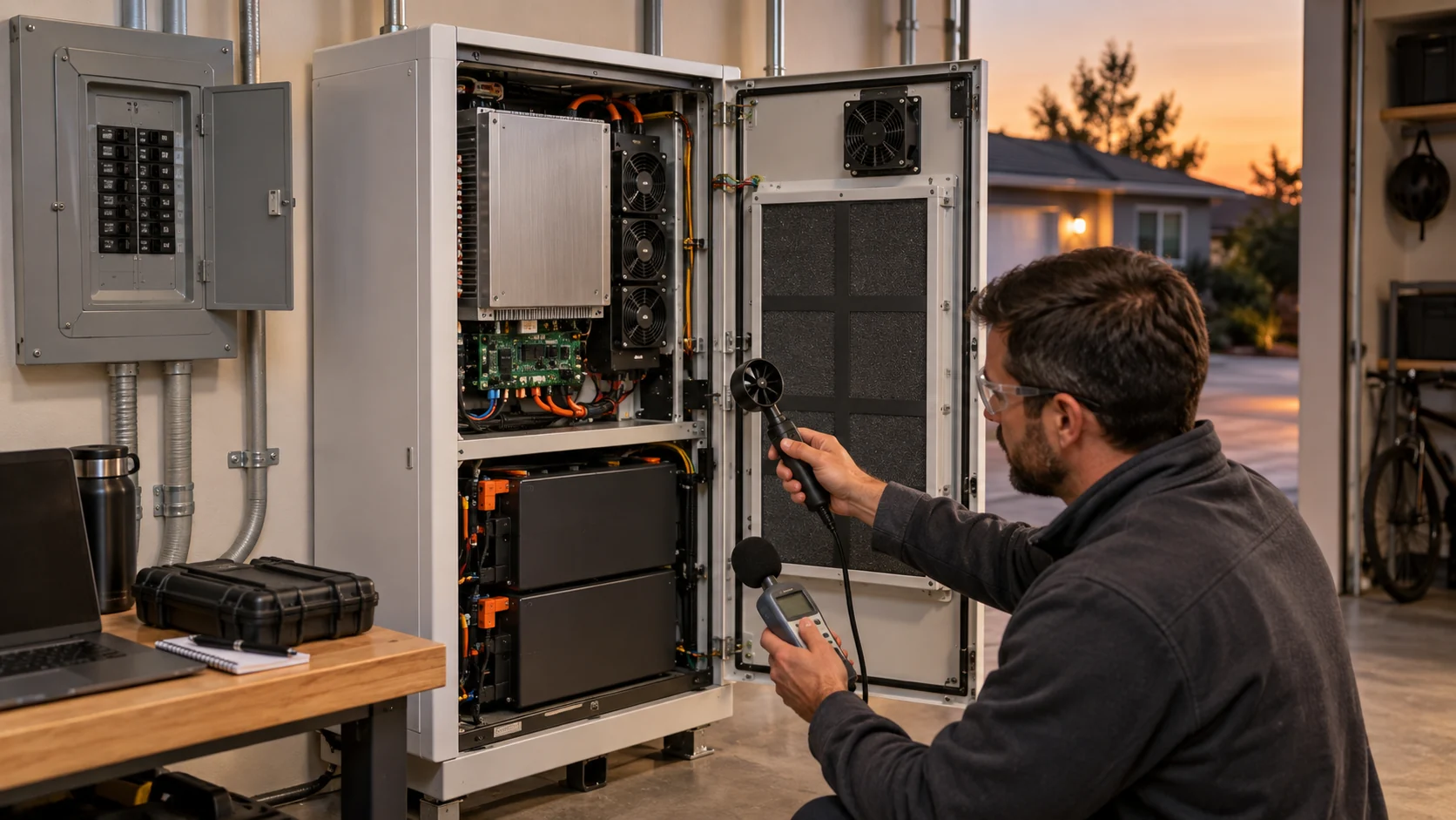
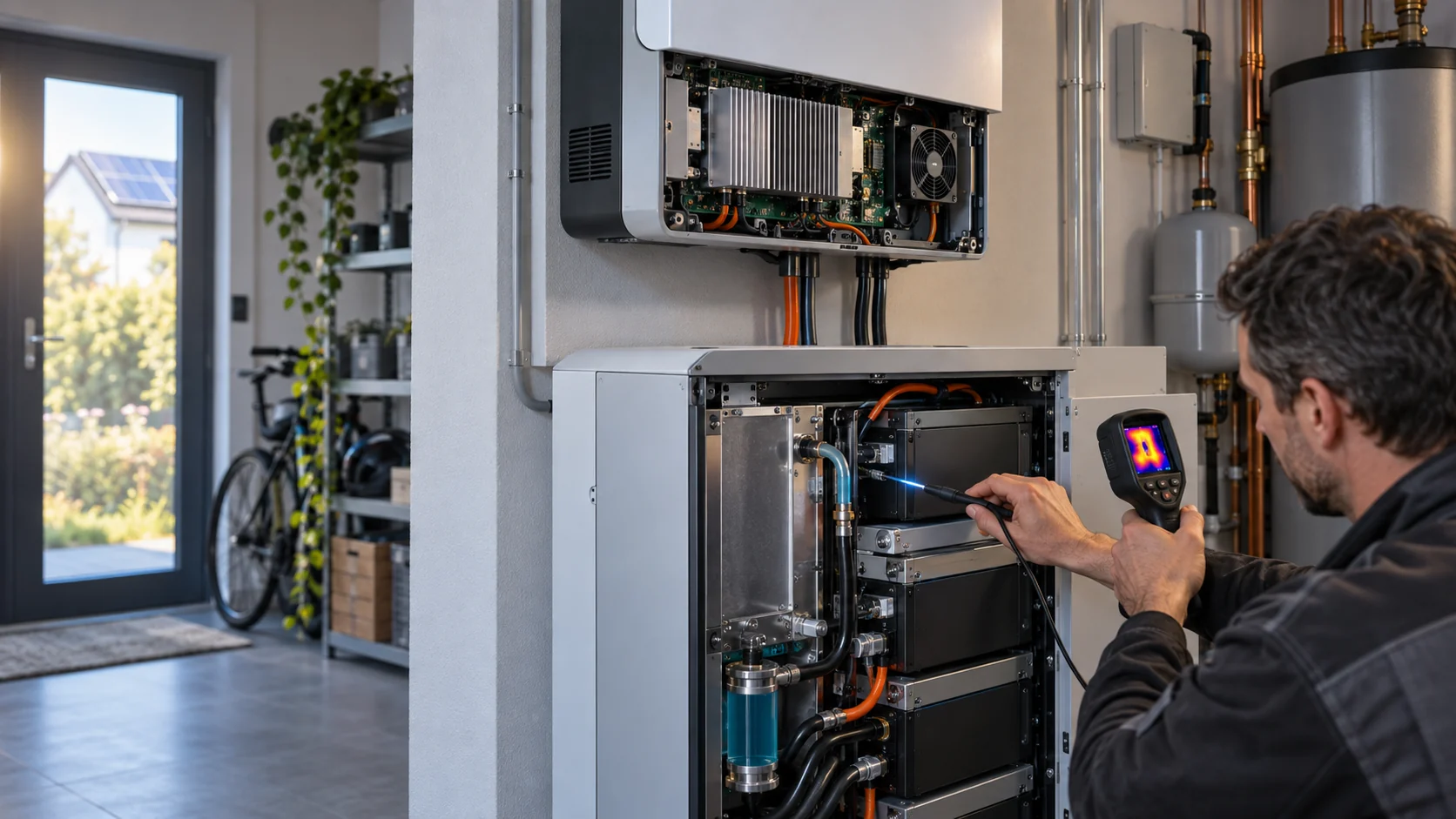
During a prototype test, measure air temperature before and after the critical module rows, and repeat the measurement at low, nominal and peak fan commands. If practical, use a traverse or a temporary flow grid to compare branch airflow. A simple smoke or tuft check can reveal recirculation, but it does not replace a quantitative pressure or temperature measurement. Record the instrument location and uncertainty with the result.
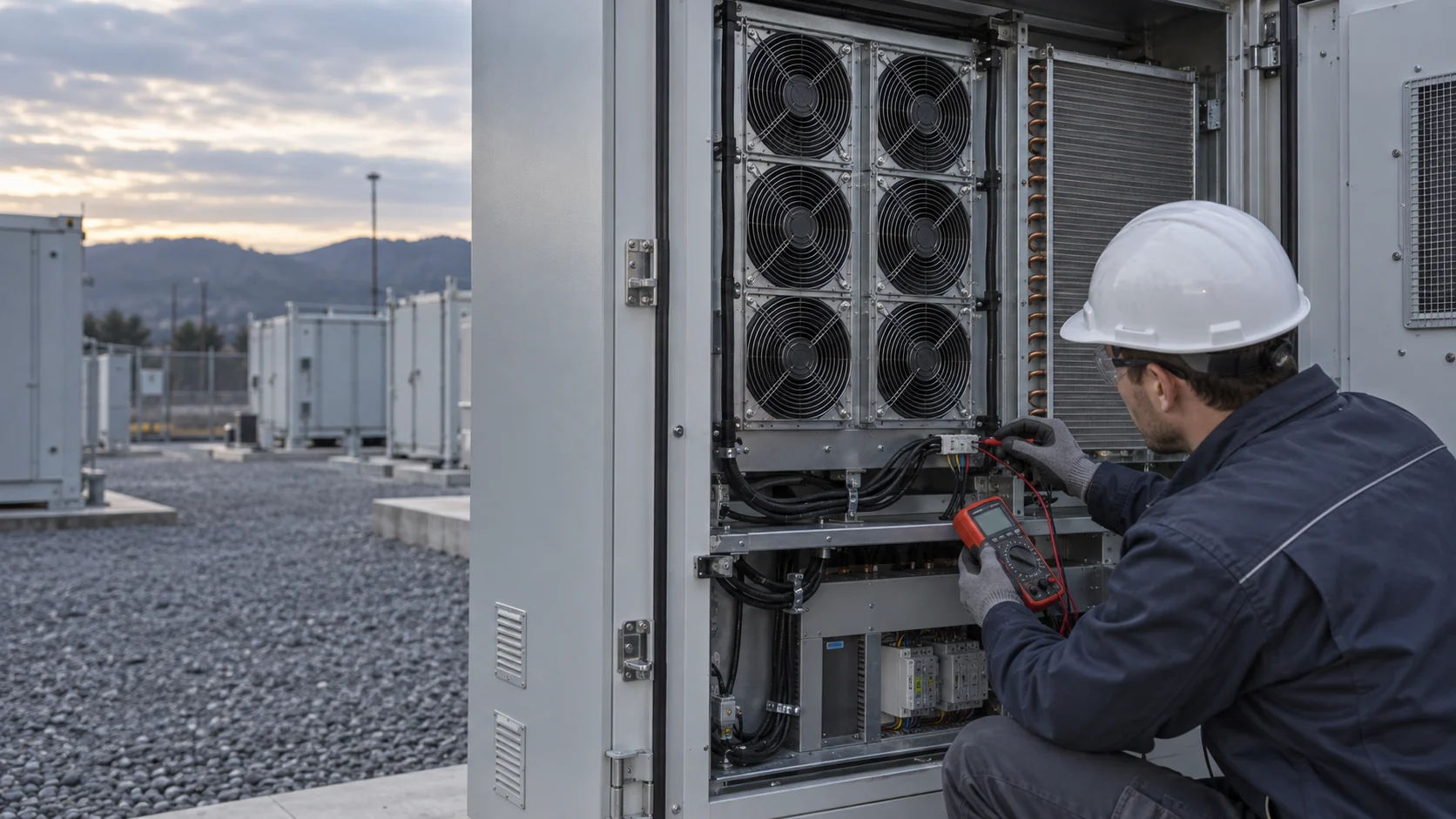
If a fan array is used, check the failed-fan and reverse-flow states as well as the normal state. A stopped fan can become a parallel leakage path, and a neighbouring fan can drive air backward through it. The correct fix may be a damper, a check arrangement, a different fan spacing or a control change. It is not safe to assume that adding one more fan automatically creates useful N+1 capacity.
Choose voltage and control signals with the cabinet controller
The electrical interface is part of the thermal design because a fan that cannot start, report speed or respond to an alarm cannot deliver a validated cooling function.
Record the actual supply range at the fan connector, not only the nominal cabinet bus. Include converter tolerance, wiring drop, startup transients and the voltage during a battery or auxiliary-power transition. Then match the exact fan variant's voltage range and starting behaviour. A 24 V label does not prove that every 24 V variant has the same minimum start voltage, current, connector or protection behaviour.
For PWM control, record the controller voltage reference, frequency, minimum duty, start duty and restart behaviour. For FG or RD, define pulses per revolution, pull-up voltage, alarm state and the input threshold. If the controller uses a tach signal to decide whether to enable the next operating state, test the entire logic during start, stall, locked rotor and power recovery. These details belong in the acceptance procedure, not only in the wiring diagram.
MEGA catalogue records can be used to screen frame size, voltage examples, airflow, pressure, current, power, speed, noise and control options. The final variant still has to be checked against the actual BESS interface and tested in the enclosure. Where the catalogue does not answer a control or environment question, record it as an open item instead of filling the gap with a generic assumption.
Account for ambient, condensation and outdoor exposure
Outdoor BESS cabinets combine thermal load with dust, salt, humidity, rain and rapid temperature changes.
The fan selection needs an environmental basis: minimum and maximum ambient temperature, altitude, humidity, condensation risk, dust or salt exposure, wash-down practice and expected service interval. These conditions affect air density, pressure loss, materials, bearings, electronics and the filter maintenance plan. Do not convert a requested IP rating into a product claim unless the exact fan record and test scope support it.
Condensation deserves a separate state in the test plan. A cabinet can cool below the dew point after a night-time shutdown or a rapid weather change. The control system may need a warm-up or purge strategy, but that decision belongs to the system integrator and the equipment safety requirements. The fan supplier can review the required airflow, temperature and control behaviour; it does not replace the enclosure condensation or battery safety design.
At altitude, use the actual density in the heat-balance calculation and make clear whether the fan curve is corrected or measured at that density. At salt-fog sites, review material and coating requirements with the responsible system owner. Keep these as engineering inputs and validation conditions, not as a promise that every catalogue series is outdoor-ready.
Validate the fan in the real cabinet
A bench run proves that the fan operates. A cabinet validation proves that the cooling design works.
The minimum validation set should include the fan-side voltage, current, command, speed or tach, airflow, static pressure and temperatures at the protected components. Repeat it at clean and loaded-filter states, low and high ambient where practical, and at the intended charge, discharge and standby commands. If the cabinet uses parallel fans, include the planned single-fan fault state and verify the alarm response.
Use a documented fixture and acceptance table. Define the measurement point for pressure, the airflow method, the temperature sensor location, the allowed stabilization time and the uncertainty. A result without those details is hard to compare between a first sample and a production-intent sample. Keep the product data, test data and system assumptions in separate columns so that catalogue values are not mistaken for measured cabinet results.
When replacing a premium reference fan, compare both candidates at the same pressure, airflow, voltage, command and environment. Matching the frame size or free-air CFM is not an equivalence test. If the candidate needs a different connector, control curve or mounting seal, include those changes in the system review before approving it.
A useful sample report also records what was not tested. If the filter was clean only, say so. If the test used a room-temperature bench supply rather than the cabinet converter, say so. If the temperature sensor was outside the hottest module row, show the limitation. Transparent gaps make the next sample more efficient because the engineering team knows whether it needs a better fan, a better air path or simply a better measurement.
Recommended catalogue starting points
These are starting points for an engineering conversation, not automatic BESS selections.
A larger frame may reduce speed for a given airflow, while a thicker or high-pressure variant may be better when the filter and module path dominate. The correct choice depends on the installed duty and the environment. Request a sample recommendation after sharing the heat load, airflow, pressure, voltage, control interface, noise target and environmental conditions.
Engineer FAQ: BESS cabinet fan selection
Use the fan to solve a defined air-side duty; do not use a fan datasheet to define the cabinet safety function.
Q: How much airflow does a BESS cabinet need? A: Start from the air-side heat load, air density, specific heat and allowed temperature rise. Then add the installed pressure requirement and validate the distribution across the modules.
Q: Is the clean-filter airflow enough for approval? A: No. Define a loaded-filter state and repeat the pressure, airflow and component-temperature checks.
Q: Can I select a fan by 120 mm frame size? A: No. Frame size narrows the mechanical search; it does not prove airflow, pressure, control, noise or environmental suitability.
Q: Does MEGA supply BESS cabinets or emergency ventilation? A: No. MEGA develops and manufactures custom cooling fans and supports fan selection, air-path review and sample validation. The cabinet, fire system, liquid loop, controller and emergency ventilation function remain with the responsible system integrator.
Q: What should I send for a sample recommendation? A: Send the heat load, required airflow and static pressure at that airflow, temperature and altitude basis, voltage range, PWM or FG/RD interface, connector, available space, noise target, environment and quantity.
Questions for a design review
Use these questions before releasing a BESS cooling fan package.
- What heat load is the fan responsible for, and which operating state produces it?
- What air density and allowable temperature rise were used in the first airflow estimate?
- Which grille, filter, module path and outlet losses make up the pressure budget?
- What is the defined loaded-filter state, and how will it be detected?
- Where are the pressure taps, airflow measurement points and component temperature sensors?
- What happens when one fan stops, reverses flow or reports an FG/RD alarm?
- Does the supply remain inside the exact fan variant's operating range during startup and transitions?
- Which requirements belong to the system integrator rather than the fan supplier?
From BESS duty point to a validated custom fan sample
MEGA Tech develops and manufactures custom cooling fans — from fan selection, air-path review and sample validation to volume production. For a BESS project, we can review the required frame and thickness, airflow and static pressure at that airflow, voltage, PWM, FG or RD output, connector, noise target and environmental constraints, then define a sample test around the customer's cabinet.
Send the heat load, target airflow, static pressure, temperature and altitude basis, supply range, control interface, connector, available envelope, noise measurement point, environment, quantity and the clean or loaded-filter acceptance condition. We will separate catalogue starting points from values that must be measured in the assembly.
Our scope is the custom cooling fan and its validation in the customer's equipment. We do not supply the battery cabinet, coil, liquid loop, unit controller, cabinet safety design or emergency ventilation function. If you need a sample recommendation, send the operating point and constraints to inquiry@cnmegatech.com or use WhatsApp at +86 135 7056 7086.