The 5°C difference nobody budgets for
A battery pack rarely fails as a whole. It fails at its weakest cell — and uneven cooling is what creates that weak cell.
In a battery energy-storage system (BESS), thousands of cells share one pack. During charge and discharge they all generate heat, but they rarely reject it at the same rate. Cells near an inlet run cool while cells deep in a tier, or inside a middle rack, climb. That spread is the problem, not the average.
The engineering consequence is clear even when the exact percentage is chemistry-specific: a persistent temperature spread drives cells through different aging rates, capacity and resistance, so the BMS must protect the weakest cell in the series string. The familiar 10°C life rule is a useful screening heuristic, not a universal battery law; usable life depends on chemistry, state of charge, current, calendar time and the temperature profile. A 5°C pack-spread limit can therefore be a reasonable project target, but it must be tied to the cell supplier's aging data rather than presented as a guaranteed 10–15% performance penalty.
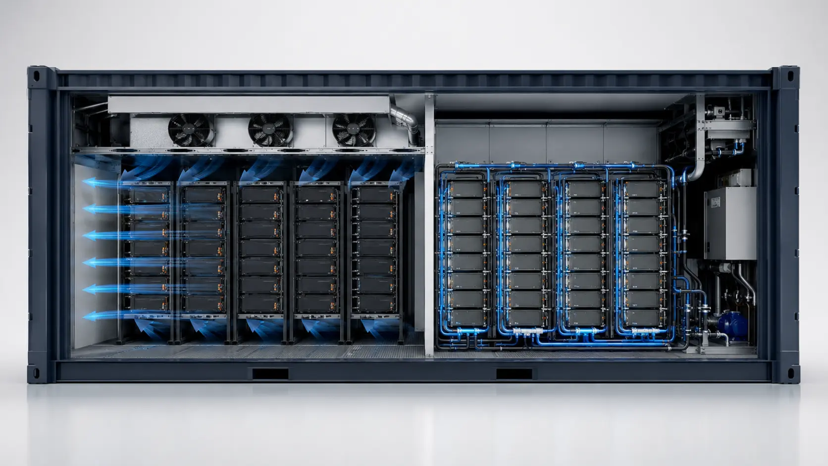
Large air-cooled containers can show larger gradients when the airflow path is not balanced, while liquid-cooled designs can tighten the spread when the cold plates, manifold and flow control are properly matched. Use ±3–5°C for air and ±1–2°C for liquid only as early design targets, not universal product ratings. The container-level measurement is the one that matters because module-level uniformity can hide rack-to-rack or zone-to-zone drift.
The aging penalty is also asymmetric, which is why averages mislead. Lithium-ion cells age faster at high temperature and at high charge states, but a cell that cycles cold in the same series string ends up at a different capacity and internal resistance than its hot neighbour — so the BMS must charge and discharge the whole string to the limits of the weakest cell. The cool cells give away usable capacity to protect the hot ones, and the imbalance compounds every cycle. Uniformity is not a comfort metric; it is the mechanism by which a pack behaves like one battery instead of a thousand competitors.
Air cooling: cheap to buy, costly to balance
Air cooling uses fans to move filtered outside air or recirculated interior air across the battery modules, then exhausts it. Its appeal is simplicity: no coolant loop, no pump skid and maintenance that can often be handled by electrical and HVAC technicians. First cost depends on the enclosure, fire system, filters, climate and control architecture, so a fixed percentage premium or saving should not be reused across projects.
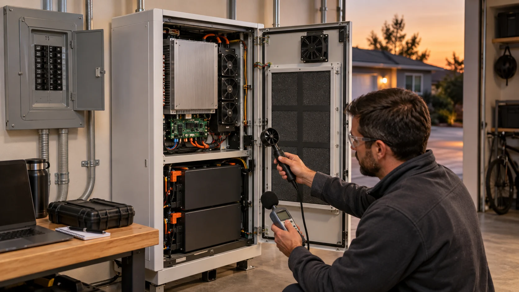
The catch shows up under load. Air has low volumetric heat capacity, so fans must move a lot of it to remove a useful amount of heat. That raises the demand on airflow and, critically, on static pressure: the air must be pushed through filters, ducts and the narrow gaps between tightly packed cells. Auxiliary power and sound pressure are project measurements, not universal constants; use the fan input-power curve, filter condition, operating duty and measurement distance to build the real budget.
The deeper problem is uniformity. Because air takes the path of least resistance, it readily bypasses the cells it was meant to cool. A common airflow-bypass pattern leaves some cells starved while others are over-cooled. Published CFD work on optimized BESS air flow shows the fix: adding guidance and redistributing the flow cut average battery temperature by about 4.6°C and the maximum temperature difference by about 3.7°C, and improved flow-velocity uniformity by roughly five times.
Those gains are real but they come from careful duct and deflector design, done case by case. That is design effort an integrator must budget for — and it is the difference between an air-cooled container that ages evenly and one that quietly bakes its middle racks.
One more air-side reality gets missed in year-one specs: filters load up with dust. A fouled filter raises the system static pressure the fans see, moving the operating point up the P-Q curve toward lower flow exactly when summer ambient is highest. Selecting the fan with margin above the clean-filter duty point — and pairing it with a filter-maintenance schedule tied to measured airflow or fan speed, not the calendar alone — is what keeps the flow design you engineered still valid in year three of a desert site.
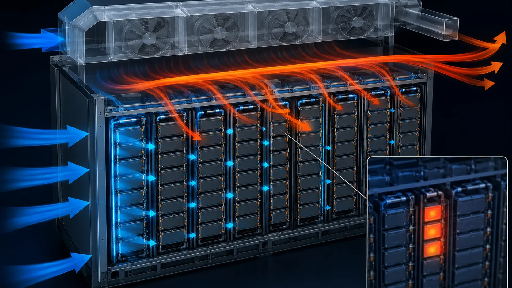
Liquid cooling: uniformity is the real product
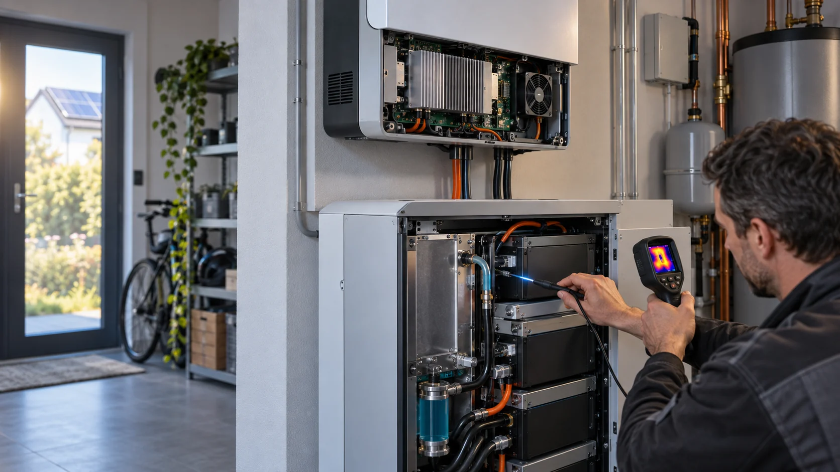
Liquid cooling circulates a specified water-based or dielectric fluid through cold plates or cooling plates coupled to the cells or modules and rejects the heat at a heat exchanger. The fluid, glycol concentration, filtration, pressure drop and materials must follow the battery and coolant supplier's compatibility specification. Water's volumetric heat capacity is roughly 3,500 times that of air at the same temperature rise, so a liquid loop can remove heat at the source without moving the same heat volume as bulk air. The thermal-management unit typically includes pumps, a heat exchanger, expansion volume, filtration and sensors that modulate flow.
That direct coupling can produce tighter cell temperatures, but values such as ±1–2°C for liquid, ±3–5°C for air, 90% round-trip efficiency or 2–3% auxiliary power are indicative design targets, not universal product ratings. Compare both architectures at the same cell chemistry, ambient condition, charge/discharge profile, enclosure, pump/fan duty and measurement boundary. The correct question is the measured temperature map and total auxiliary energy at the required operating point.
The trade-offs are upfront cost, a pressure-tested coolant loop, and a maintenance discipline that must be budgeted from day one. The coolant is consumable: levels get checked and topped up, the water–glycol mixture is replaced every few years as additives degrade, filters get swapped, and corrosion is watched. Leak detection has to be designed in, not bolted on — a slow unseen leak is how a hot spot and a derate start. And on a merchant project, redundancy is not optional: N+1 pumps with automatic changeover, redundant power feeds and automatic leak detection are the difference between a non-event and a forced outage during a summer price spike.
Beyond cold plates, the menu keeps growing: single-phase immersion uses dielectric fluid, phase-change materials can buffer short thermal spikes, and direct-expansion refrigerant can skip an intermediate water loop. Each option changes materials compatibility, service, detection and safety validation. In practice, many projects are hybrids — liquid for the cells, air for the balance of plant — and the selected architecture must be validated against the applicable battery and installation requirements rather than treated as a default.
| Criterion | Air cooling | Liquid cooling |
|---|---|---|
| Cell temperature uniformity | ±3–5°C | ±1–2°C |
| Parasitic load | 3–5% of capacity | 1–2% of capacity |
| System efficiency | 88–92% | 93–97% |
| Hot-climate COP (>35°C) | 1.8–2.2 | 3.0–4.2 |
| Maintenance complexity | Low (fans, filters) | Moderate (pumps, fluid, leaks) |
Where the 5 MWh line actually sits
The industry has not drawn a hard rule, but the pattern is consistent. Below roughly 1–2 MWh — residential and small commercial systems, and cabinets under about 250 kWh — air cooling remains a reasonable, lower-cost choice. From about 1–5 MWh it becomes a genuine either–or decision that depends on climate, duty cycle and service capability.
The line itself has been moving as cell formats and pack layouts change. Public product announcements now span several container energy ratings, but the comparison is not apples-to-apples: usable energy, cell chemistry, enclosure volume, ambient design point and thermal limits all change with the product. Do not turn a 3–5 MWh label into a cooling rule. At higher packing density, the cell pack gives the air path less room to distribute heat, and the fan power, temperature spread and service burden must be compared against a liquid option using the same duty cycle and measurement boundary.
The market is moving toward liquid cooling for some higher-density utility systems, but adoption share, market size and payback vary by region, chemistry, project duty, climate and supplier definition. Do not turn a market forecast into a design rule. Build the business case from measured auxiliary power, expected cycling, cell-life data, coolant and maintenance costs, and the cost of the required fire and control systems.
A rough parasitic account still shows why the comparison matters. If an engineering scenario uses a 2–3 percentage-point auxiliary-energy difference on a 5 MWh container cycling once a day, the annual throughput is about 1,825 MWh and the implied difference is roughly 36.5–54.8 MWh per year. That is an arithmetic scenario, not a measured air-versus-liquid result; replace the percentages with the selected system's input-power data before calculating payback. If the specification keeps climbing in size, compare the liquid option early rather than locking in a thermal ceiling that later requires a retrofit.
Even a liquid-cooled container still needs airflow
Choosing liquid for the cells does not retire the fans — it moves them to the rest of the container.
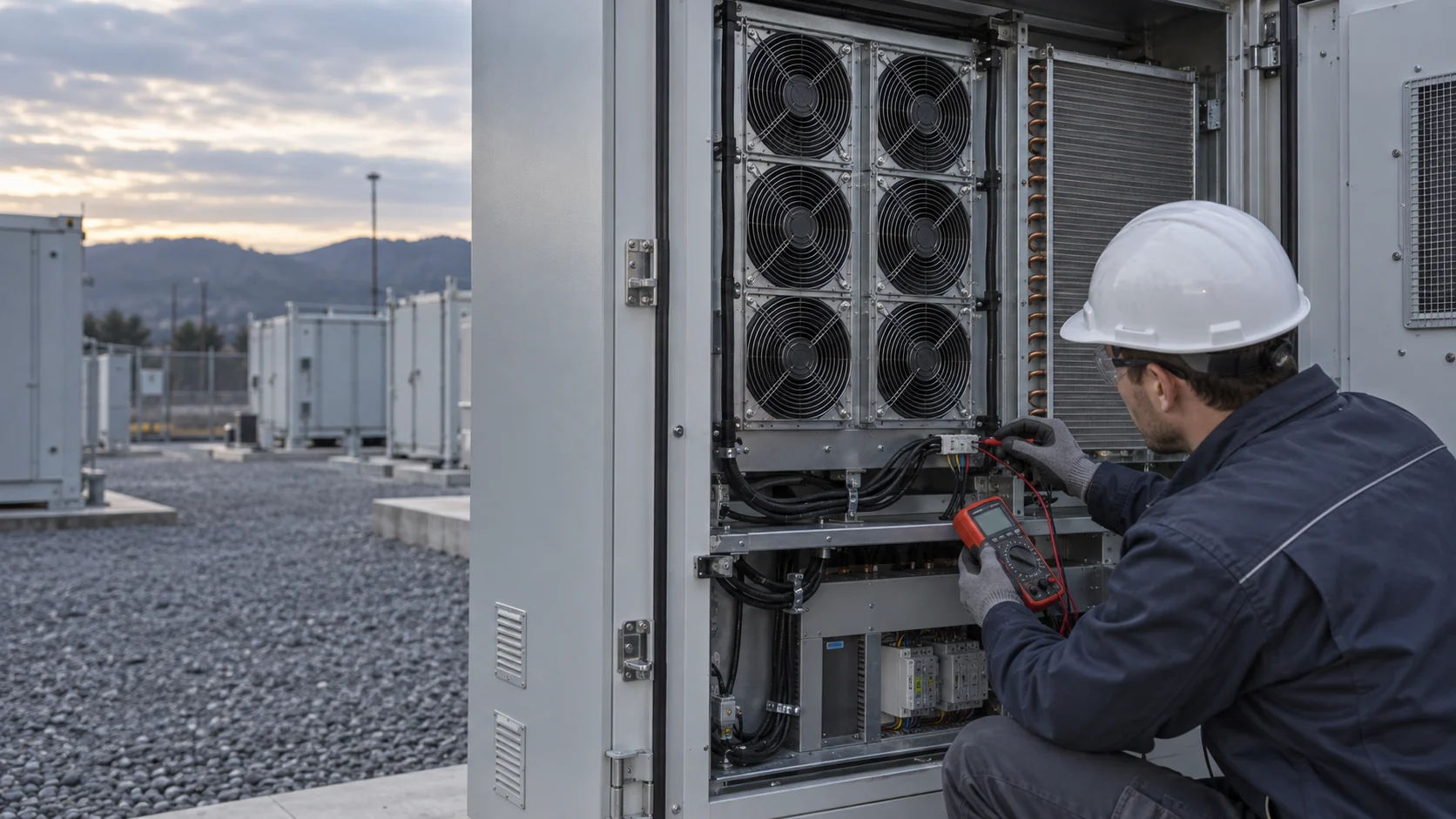
Open the specification of a liquid-cooled container and you may still find a forced-air layer. The chiller or dry-cooler that rejects the loop heat uses condenser fans; the power conversion system (PCS) and transformer compartments may be air-cooled; control cabinets and balance-of-plant electronics still need their own thermal path. The cells may ride on cold plates, but the remaining equipment still breathes air — and those fans have their own static-pressure, ambient and ingress-protection budget.
Two interactions deserve explicit design attention. First, fire and gas management: ventilation, pressure relief, detection, suppression and fan shutdown or purge logic must be coordinated with the applicable project code and test plan. Do not assume a particular extinguishing agent or fan state without the fire-system designer's sequence of operations. Second, noise: liquid-cooled containers may remove some large air handlers, but condenser and cabinet fans remain audible at night-mode sites; PWM speed control tied to load, not a fixed duty, is what keeps the acoustic claim honest.
This is where fan specification stays a live decision in every BESS architecture: condenser and radiator airflow for the heat-rejection skid, cabinet cooling for PCS and control electronics, each with its own airflow path, duty cycle and ingress-protection requirement. MEGA Tech’s DC axial range — with PWM control, FG/RD speed feedback and dual-ball-bearing options — covers these auxiliary roles in both air-cooled and liquid-cooled containers.
If you stay with air: design the flow, then pick the fan
Air-cooled BESS fails on flow distribution before it fails on fan selection. Do the flow design first so the fan can do its job.
State the thermal budget in engineering terms, not a CFM wish: required airflow at the operating point, the static pressure to overcome filters, ducts and cell gaps, the supply voltage and current budget, and the ambient range with margin. Only then choose a fan whose P-Q curve meets that system curve — not a free-air ceiling. A fan chosen from its free-air number stalls in exactly the high-resistance duct a packed container gives it, and the bypass pattern above is the visible symptom.
For container and rack-scale airflow where several fans drive air against ducts and filters, large high-pressure DC axial fans are the practical starting point. MEGA Tech’s catalogue includes 172 mm and 200 mm DC axials built for exactly this kind of ducted, high-resistance path.
Build the control and monitoring layer in at the same time: PWM speed control tracks the pack’s real heat load instead of running fans at full duty all night, FG/RD feedback turns a stalled fan into an alarm instead of a hot-cell surprise, and an N+1 fan arrangement keeps the container derating gracefully rather than tripping when one unit fails. In a system whose warranty depends on temperature evidence, a fan that can report its own health is part of the thermal design, not an accessory.
- Target 200 mm for the highest airflow per fan: the MG20060VHH48X delivers about 645.6 CFM at 22.02 mmH2O, 48 VDC, in a 200×200×60 mm envelope.
- Where the path is more restricted, the 172 mm MG17251HV48X gives higher static pressure — about 45.4 mmH2O with 12 VDC or 48 VDC options.
- Dual ball bearings are available across these series for a 24×7 utility duty cycle; confirm PWM, FG/RD feedback and IP options for the selected model.
- Series that push air in parallel across filter banks include the 172 mm VH and high-speed variants (see catalogue links below).
Do not forget the outside of the container
Whether you cool the packs with air or liquid, the container shell still exchanges heat with its environment. A container sitting in direct sun faces solar gain on top of the battery load. Consider the ambient design temperature with real margin rather than an average-summer figure, and allow repeatable airflow across the container’s own ventilation and any heat-rejection coils — a liquid-cooled container still needs its chiller or radiator airflow engineered, and that is fan territory even when the cells are not.
Fire safety shapes the shell too. Prevention, detection, containment and suppression must be treated as one system. Look for pack-level detection, UL 9540 certification where applicable, and UL 9540A test evidence for the relevant cell, module, unit and installation configuration. Also review containment, ventilation for fault gases and ingress protection that keeps desert dust and coastal salt out of the drive electronics. Those environmental requirements are exactly where an axial fan's bearing and IP specification deserves its own decision, separate from the pack-cooling choice.
Do not treat a cooling change as a shortcut around the safety evidence. UL Solutions describes UL 9540A as a staged method covering cell, module, unit or installation behaviour depending on the product and test path; the applicable edition, test level and representative installation must be agreed with the battery supplier, authority having jurisdiction and fire-safety team. The fan can support ventilation or heat rejection, but it cannot by itself establish thermal-runaway propagation performance.
From BESS requirement to a production-ready fan
A BESS fan is not selected by cabinet size alone. It is developed around the actual air path, duty cycle and environmental requirement.
MEGA Tech can support the fan side of an air-cooled or hybrid BESS design from the first requirement. We review the cabinet or container layout, heat load, target temperature spread, filter and duct resistance, ambient range, noise limit, voltage, control signal and expected duty cycle, then recommend a suitable fan platform or define the adjustments needed.
If the catalogue variant does not fit the product, we can develop a customized sample around the application: airflow and pressure target, fan size and thickness, speed range, PWM or FG/RD feedback, bearing choice, connector, cable length, ingress protection and other integration details. The sample is tested in the intended cabinet or representative airflow path, refined with the product team, and then transferred into controlled volume production.
This sample-first path is especially useful for new storage products and smaller development programs. The team does not need to commit to a large production order before the fan has proved its thermal value; it can validate the cooling design first and scale the approved solution as the product moves toward the market.
- Define the air path and operating point before choosing the fan.
- Build a sample around the real voltage, control, connector and environmental requirements.
- Test airflow, pressure, temperature uniformity, noise and reliability in the target enclosure.
- Scale the approved fan specification into reliable, cost-conscious production.
Engineer FAQ: Air Cooling versus Liquid Cooling in BESS
BESS thermal design is a coupled heat-management and safety problem; the cooling method must be selected with airflow, liquid, controls and protection boundaries together.
Q: Is liquid cooling automatically better than air cooling for every BESS? A: No. Liquid can reduce local thermal gradients and improve heat transfer near cells, but it adds pumps, coolant compatibility, leak control and service complexity. Air cooling can be practical for lower or mixed loads when the airflow path, temperature uniformity, filtration and safety case are validated for the actual enclosure.
Q: When should a BESS team choose air cooling? A: Air is a candidate when the heat load, allowable cell temperature spread, ambient range, enclosure volume and service plan can be met with a measured air path. Build the rack or module system curve including filters, baffles, seals, gaps and exhaust restrictions, then check local cell or module temperatures rather than total CFM alone.
Q: What does liquid cooling solve, and what does it not solve? A: It can move heat from covered cells or modules more effectively, but it does not automatically solve thermal runaway propagation, uncovered components, coolant leaks, control faults or uneven module conditions. The battery safety analysis, monitoring, isolation and fire-protection strategy remain separate system requirements.
Q: Is there a universal temperature spread or airflow target for a battery rack? A: No. The acceptable temperature range and spatial spread depend on chemistry, cell format, module design, operating state, ambient conditions and the applicable product and installation requirements. Define the limit with the battery and safety teams, then validate it at the required charge and discharge states.
Q: How should an air-cooling fan be selected for BESS? A: Start from measured heat load and allowable air temperature rise, then solve the fan P-Q curve against the complete rack impedance. Check clean and loaded filters, bypass paths, inlet temperature, noise, power, control range, fault response and temperature distribution across representative modules.
Q: What must be checked in a liquid-cooling loop? A: Define coolant chemistry and wetted-material compatibility, flow and pressure limits, heat-exchanger approach, pump redundancy, leak detection, isolation, filtration, expansion and the response to loss of flow or communication. Flow and temperature sensors should be validated against the actual thermal load, not used as a substitute for cell-temperature measurement.
Q: Can an N+1 fan arrangement replace thermal-runaway protection? A: No. Fan redundancy can preserve cooling after a defined fan fault, but it does not replace cell monitoring, electrical protection, thermal-runaway detection, isolation, gas management, fire protection or the applicable BESS testing and installation requirements.
Q: What should a customized BESS fan sample prove before production? A: Test the representative enclosure or module path with the real cells or thermal load, filters, seals, baffles, controller and mounting. Record airflow distribution, pressure, cell or module temperatures, inlet temperature, voltage, RPM, current, noise, fault response and clean or loaded-filter behavior, then carry the approved configuration into repeatable production.
- Tie every numerical answer to voltage, speed, temperature, mounting and test condition.
- Separate catalogue maximums, engineering estimates and measured application results.
- Use the FAQ to define the next measurement or sample-validation step.
Final review checklist
A defensible BESS cooling decision is a documented one that survives the move from datasheet to deployment.
The fan subsystem is one part of that boundary. Fan selection and sample validation should confirm airflow, pressure, temperature uniformity, noise, control response and degraded operation. BMS protection, gas detection, suppression, ventilation shutdown and thermal-runaway testing remain separate system responsibilities and should follow the applicable project requirements.
- Is the target pack temperature spread stated (aim ≤4°C for air, ≤2°C for liquid) — and measured at the container level, not just per module?
- Has the size direction been decided — will this stay under 5 MWh, or grow past it?
- For air, is the flow path designed so fan airflow reaches the cells instead of bypassing the pack?
- Is the fan picked against the system curve, not free-air CFM, with dual ball bearings for 24×7 duty?
- For liquid, are N+1 pumps, leak detection, and a coolant replacement and filter schedule in the O&M budget from day one?
- Are ambient, solar and hot-climate margins included, and shell ventilation separated from pack cooling?
- Are fire detection and UL 9540A ventilation requirements integrated with the thermal design rather than bolted on after?