N+1 Is a Test Result, Not a Fan Count
A fan wall is not redundant merely because one extra fan appears on the layout. The surviving array must keep the protected load inside its thermal and pressure limits after the defined failure.
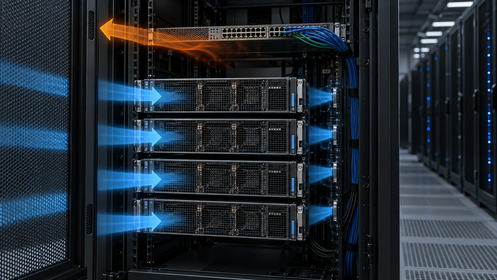
High-density AI racks make fan-wall decisions more sensitive than a simple total-airflow calculation suggests. GPU servers, network switches, storage and power shelves may have different airflow directions and different inlet temperature limits. If one fan module stops, the healthy modules may ramp up, the array operating point may move, and the failed opening may become an unintended bypass path. The result can be a local rack-inlet or component hotspot even while the room average still looks acceptable.
The correct engineering question is not how many fans are installed. It is: at the real system resistance, with one specified module unavailable, does the assembled fan wall deliver the required airflow and pressure to every critical zone, with acceptable noise, power and recovery behavior? That question must be answered with measurements or a validated model tied to the actual plenum, filters, dampers, heat exchangers and rack population.
This guide focuses on fan-wall failure validation, backdraft isolation, operating-point shift, sensor placement and acoustic evidence. It does not replace data-center electrical redundancy, fire protection, controls, commissioning or uptime requirements.
Build the Fan-Wall System Curve Before Selecting N+1
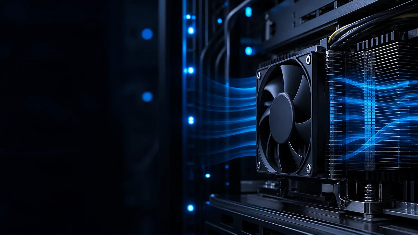
The fan wall, plenum, filter, coil, damper and rack path form one system. The duty point is where the array curve intersects that system curve.
List every pressure-producing element between the fan inlet and the rack outlet: intake screen, filter, coil or rear-door heat exchanger, turning vanes, plenum, supply path, server chassis, cable openings and return path. Use measured pressure where possible. A fan catalog's maximum static pressure is a zero-flow endpoint and does not tell you the delivered airflow in the assembled unit.
For a worked estimate, suppose the clean filter is 55 Pa, the coil is 90 Pa, the plenum and turning path are 75 Pa, the rack and server path are 180 Pa and the return path is 45 Pa. The clean system resistance is approximately 445 Pa. If the filter grows to 95 Pa, the service-state resistance rises to about 485 Pa. The fan wall must be checked at both conditions and at the design airflow, not only at a nominal free-air value.
If pressure is approximated by a quadratic system curve, a 10% increase in airflow can require roughly 21% more pressure because pressure varies approximately with Q squared. That is why a control loop that increases flow after a fan failure can consume headroom quickly. The controller should be tuned from measured pressure and temperature response rather than a guessed multiplier.
| Element | Evidence | Failure impact |
|---|---|---|
| Filter | clean and service-state differential pressure | moves the array duty point and changes power |
| Coil / heat exchanger | pressure at design flow and fouled allowance | reduces available fan margin |
| Plenum | static pressure map and velocity profile | creates uneven module loading or recirculation |
| Rack population | server/chassis pressure and airflow direction | sets the protected inlet requirement |
| Return path | door, aisle and damper pressure | can turn a local fault into room recirculation |
What Happens When One Fan Stops
A fan-stop test should capture airflow, pressure, temperature, control command and the condition of the failed opening at the same time.
When one fan stops, three changes can happen immediately. Total available fan capacity falls. The remaining fans move to a different point on their P-Q curves. The stopped module can allow reverse flow if its opening is not isolated. These effects are coupled: the healthy fans may increase speed while part of their pressure is spent pushing air backward through the idle module instead of through the racks.
Do not use a single room airflow reading as proof of N+1. Measure the fan-wall total flow, pressure upstream and downstream, and rack-inlet temperatures at the critical rows. Add local velocity measurements or a calibrated traverse when the plenum is non-uniform. The test should include the control response: detection time, ramp rate, maximum command, alarm, and the point at which the system limits workload or initiates a controlled action.
A practical pass criterion is application-specific, but it should be written before the test. For example: after one module is disabled, every critical rack inlet remains below its agreed temperature limit, the fan wall maintains the required minimum flow at the defined pressure, no reverse flow is detected through the failed module, and the controls reach a stable state without hunting.
Interactive: Follow Blue Supply Air and Red Reverse Flow
The animation shows why a stopped module can turn a redundancy test into an airflow short circuit unless a damper or other isolation method closes the path.
Use the schematic as a commissioning sequence. First record the normal state with all modules at the design command. Then disable one module and observe whether the backdraft damper closes, whether the remaining fans ramp, and whether the plenum pressure redistributes. Finally, repeat with the rack load and filter at the defined worst case. The visual is useful because the failed opening may not look like a large flow path from the front of the equipment.
Check the damper itself rather than assuming it follows the fan command. A damper can stick, flutter, leak or add more pressure than the fan-wall selection allowed. Measure leakage or reverse velocity where the application requires a quantitative limit, and inspect the mechanical clearances around the blade. If the design uses a blanking plate, automatic shutter or a special fan module, verify its service procedure and fault state.
The animation is not a CFD result and does not replace a plenum traverse. It is a qualitative explanation of why the failure state must be measured as a different airflow network, not treated as the normal network with one fan removed.

Control Logic: Fan Speed, Rack Sensors and Fault Recovery
The control loop should respond to the limiting thermal zone and preserve fault visibility rather than simply commanding every fan to maximum speed.
Use rack-inlet temperature, plenum pressure and fan feedback together. A fan tachometer confirms rotation but cannot confirm that airflow reaches a particular rack. A single sensor near the fan wall can also miss a hot row caused by bypass, poor plenum distribution or an airflow-direction mismatch. Place sensors at representative and limiting rack inlets, and document their relationship to the control zones.
After a module failure, the controller may increase the command of healthy fans. Validate the ramp rate, minimum and maximum speed, current limit, alarm delay and recovery hysteresis. If the healthy fans reach maximum command but a rack inlet continues to rise, the system should make the next protection action explicit: reduce IT power, shift workload, open a bypass path or perform a controlled shutdown according to the facility design.
For an illustrative control estimate, if eight modules each draw 0.8 A at 48 V, the array uses about 307 W at the selected command. After one fails, seven modules may need 0.95 A each to hold the same pressure, increasing fan input to about 319 W before controller losses. The numbers are illustrative only; the actual electrical result depends on the fan efficiency and operating point. The important point is that N+1 can change both airflow and power.
Acoustic Validation: The Failure State Can Be Louder Than Normal
A fan wall can meet an average dBA target and still create a narrow, distracting blade-pass tone after the remaining modules ramp up.
Blade-pass frequency is estimated as BPF = blade count x RPM / 60. A seven-blade fan at 2,400 RPM therefore has a fundamental BPF near 280 Hz. Harmonics, fan-to-fan speed variation, grille interaction, plenum reflections and structural resonance can make the tone more noticeable than a broadband measurement suggests. In a fan wall, several modules can reinforce the same frequency if their speed commands are closely aligned.
Measure normal, one-fan-down and recovery states at the operator or maintenance position. Record A-weighted sound pressure and a narrowband spectrum, and note the fan command and actual RPM. If the failed state raises RPM from 2,000 to 2,500, the BPF of a seven-blade rotor shifts from about 233 Hz to 292 Hz. A resonance or room mode near the new frequency can make the change perceptually significant even if total sound power rises only modestly.
Acoustic changes can also identify an airflow problem. A whistling damper, unstable recirculation or a crowded inlet can create a tonal signature before the rack temperature alarm appears. Treat sound as a diagnostic signal, but confirm it with pressure and airflow measurements before changing the fan selection.
Commissioning Matrix: Prove Thermal and Mechanical Margin Together
The most useful fan-wall test matrix combines airflow, pressure, thermal load, fault state and acoustic evidence in one record.
Start with a clean and stable baseline. Record fan commands, actual RPM, input power, upstream and downstream static pressure, total airflow, rack-inlet temperatures, room conditions and narrowband noise. Repeat after the system reaches thermal steady state, because a short test can miss the heat soak of a dense AI workload or a liquid-to-air heat exchanger.
Then test the defined degraded cases: one module off, one damper unable to open, one damper unable to close, a loaded filter, an obstructed inlet, an airflow-direction mismatch and a sensor or feedback failure. Not every case belongs in the final product requirement, but each should be considered during design review so that the selected fan, damper and controller have an explicit boundary.
Keep the evidence traceable. Record instrument type, calibration status, measurement location, fan firmware or control revision, module serial numbers and workload state. A result without the installed pressure and control condition is difficult to compare with a supplier P-Q curve or to reproduce during maintenance.
| State | Measure | Pass question |
|---|---|---|
| All fans normal | flow, pressure, inlet temperature, power, spectrum | Does the array meet the design point efficiently? |
| One module off | damper position, reverse flow, recovery and hotspot | Does the protected load remain within limits? |
| Loaded filter | filter DP, flow, fan command and power | Is service-state margin preserved? |
| Worst rack load | critical inlet temperatures and pressure map | Are local zones protected, not only the average? |
| Control fault | FG loss, sensor loss, command limit and alarm | Is the protective response defined and testable? |
An Anonymous Customer Example: Fan-Wall Recovery Without a False N+1 Claim
An AI infrastructure integrator had the correct number of fan modules on paper, but the failed-module test showed that pressure was being spent on a bypass path.
The integrator's initial commissioning test ran all fan modules at a moderate command and checked average airflow at the fan-wall outlet. The result looked comfortable. When one module was disabled, however, the remaining fans ramped and the rack-inlet temperature at the end of the row rose faster than the room average suggested. The failed opening showed measurable reverse movement, while the damper did not fully close under the low-pressure condition.
MEGA Tech reviewed the module P-Q data, plenum arrangement, damper geometry, control ramp and rack-inlet sensor locations. A revised fan sample with the required voltage and feedback interface was compared at the assembled pressure. The customer also adjusted the damper inspection point and added a pressure and temperature check to the failure test rather than accepting only the fan alarm.
The final validation separated two claims: the array could continue operating with one module unavailable, and the controls could identify when the remaining thermal margin was no longer sufficient. The customer did not label the design N+1 until the failed state, backflow path and rack-level temperatures were documented.
This is an anonymized engineering scenario, not a published customer performance claim. The transferable lesson is that redundancy is a system behavior. Fan, damper, plenum, sensors and controls must be tested as one assembly.
Where MEGA Tech Fits In
We help data-center and server OEM teams evaluate custom cooling fans against the real plenum pressure, control interface, noise target and failure state.
MEGA Tech can review custom DC or EC axial fans, compact blowers and fan modules for server chassis, fan walls, rear-door air paths and auxiliary cooling sections. The engineering review can include P-Q behavior, pressure margin, PWM or voltage control, FG/RD feedback, startup, module matching, bearing selection, vibration, acoustic spectrum, connector position, environmental protection and small-batch samples validated on the customer's assembly.
For a first review, provide the target airflow at static pressure, plenum and filter layout, fan quantity and failed-module condition, voltage range, control interface, feedback requirement, inlet temperature, altitude, noise limit, service-state pressure, rack load and expected quantity. If a replacement is being considered, send the current fan part number and the measured operating point; outline dimensions alone are not enough to prove equivalence.
We also support cost-competitive replacement fans for Sanyo Denki, SUNON, Delta, NMB and ebm-papst when the replacement is evaluated at the same installed pressure, mounting, voltage, feedback, acoustic and redundancy conditions. We do not supply the data-center cooling plant, server controller or facility safety system; our scope is the fan and air-side engineering interface.
Engineer FAQ: AI Fan-Wall Failure and Noise Validation
These questions turn a fan-wall drawing into a commissioning plan that an engineer can sign off.
Q: Is a fan wall with one extra fan automatically N+1? A: No. N+1 requires the assembled system to meet the defined thermal, airflow and pressure limits after one specified module is unavailable.
Q: Why is reverse flow through a failed fan a problem? A: It can short-circuit pressure from healthy modules and reduce the airflow reaching server or rack heat sinks.
Q: Do I need a backdraft damper on every module? A: The correct isolation method depends on the design, but every idle opening must have a validated leakage and reverse-flow behavior.
Q: Can rack-inlet temperature alone prove fan-wall performance? A: No. Combine rack temperatures with total flow, plenum pressure, module feedback and the actual workload state.
Q: Why can the failed state be noisier? A: Remaining fans may run faster, shifting blade-pass frequency and increasing tonal interaction with the grille, plenum or structure.
Q: What data should I send for a custom fan review? A: Send airflow at pressure, fan size, voltage, PWM or EC interface, FG/RD requirement, inlet temperature, altitude, noise limit, filter condition, quantity and failure strategy.
Q: Can MEGA Tech build small fan-wall samples? A: Yes. We can adjust parameters and interfaces, build samples and support P-Q, thermal, acoustic, feedback and failure-state validation before production.
Fan-Wall N+1 Review Checklist
Use this checklist before approving the fan wall, damper, control curve or replacement module.
- Was the fan wall selected from the assembled system curve rather than free-air CFM?
- Were clean and service-state filter pressures included?
- Was one module disabled at the worst intended AI workload?
- Did the failed opening close or otherwise meet its reverse-flow limit?
- Were plenum pressure and rack-level temperatures measured, not only room average airflow?
- Did surviving modules reach a stable command without hunting or exceeding current limits?
- Were rack-inlet sensors placed at representative and limiting zones?
- Was normal and failure-state acoustic spectrum recorded, including BPF and harmonics?
- Were FG/RD, sensor failure, damper fault and control fallback tested?
- Are measured values, estimates, supplier curve data and facility limits clearly separated?