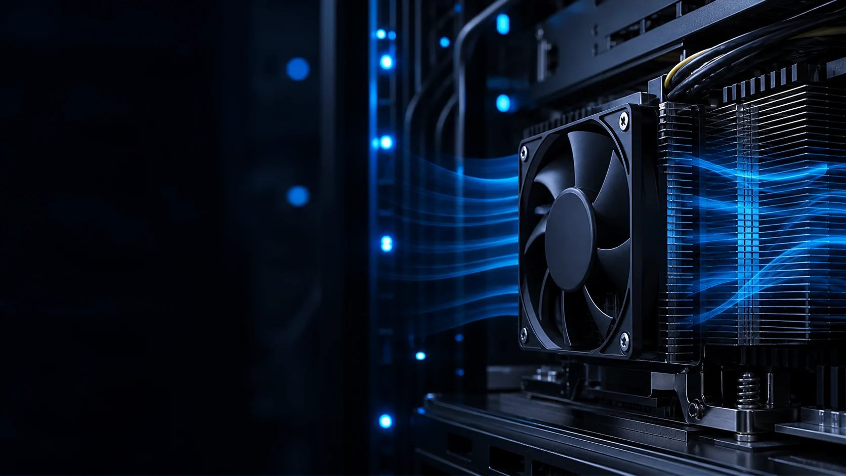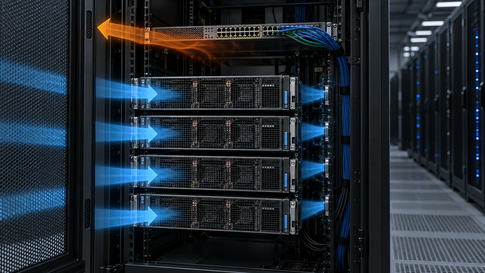
A Room-Average Temperature Can Hide a Rack-Inlet Problem
AI racks do not consume the room average; they consume the air arriving at their own inlets.
High-density GPU and accelerator racks make airflow control more sensitive to sensor placement. A room thermostat or return-air sensor may report a stable value while one row sees warm recirculated air, another row receives excess cold supply, and a third row is protected only because its servers are running a lighter workload. The fan wall may be operating normally while the rack inlet condition is already outside the intended margin.
ASHRAE's AI data-center guidance emphasizes air management, containment, right-sized airflow and granular rack-inlet monitoring. That is not a request to place a temperature sensor everywhere without a control plan. It means the measurement used for control and alarm must represent the air the IT equipment actually draws, while the fan system still respects pressure, redundancy, acoustic and maintenance constraints.
This guide explains how to connect rack-inlet sensors to fan-wall control and commissioning. The numerical examples are engineering estimates to show the method. They are not a universal operating limit for every GPU platform, facility or ASHRAE equipment class.
Place Sensors Where They See the Equipment Air
A sensor is only useful when its reading is representative, repeatable and connected to an action.
Start with the rack front and identify the actual intake plane. A sensor mounted too close to a perforated floor tile can read supply air before it mixes. A sensor mounted above the rack can read room air instead of the inlet. A sensor placed in the centre of a row can miss an end-of-row recirculation pocket. For a dense AI row, use a vertical set of points or a validated representative location rather than assuming one wall sensor represents every rack.
Use the commissioning survey to compare sensor readings with a calibrated probe or temporary data logger. Measure top, middle and lower rack inlet positions, near and far ends of the row, and the hot-aisle or return side. Record containment doors, blanking panels, cable openings and adjacent rack load because these can change the local air path.
For an illustrative sensor-placement check, imagine a row with inlet temperatures of 21.8, 22.4, 23.1, 24.6 and 25.2°C from near to far. The row average is 23.4°C, but the far-end point is 1.8°C above the average and may respond first to a containment leak or fan-wall imbalance. A single middle sensor would not reveal the gradient.
| Location | What it reveals | Common interpretation error |
|---|---|---|
| Rack inlet top | upper-layer recirculation and ceiling effects | assuming the top value equals the whole rack |
| Rack inlet middle | representative equipment intake condition | using it as the only control point |
| Rack inlet bottom | floor supply, tile or under-rack bypass | ignoring cable openings and floor leakage |
| Near/far row ends | distribution imbalance and containment leaks | averaging away the worst rack |
| Hot aisle or return | heat removal and recirculation path | controlling supply fans from return air alone |
The Fan Wall Must Be Selected at the Installed Pressure
Parallel fans increase available flow, but the system still runs at the intersection of the combined fan curve and the room resistance curve.
A fan wall normally includes filters, coil or heat exchanger surfaces, guards, dampers, transitions, containment openings, raised-floor paths or overhead ducts. Each element consumes pressure. The fan selection point should therefore include clean and loaded filter conditions, expected damper position and the actual pressure relationship between the supply and return zones.
For a worked estimate, suppose an AI row requires 48,000 m3/h at a measured external static pressure of 420 Pa. Filter loss is 110 Pa clean and 180 Pa at the service limit, coil loss is 90 Pa, containment and transition losses total 120 Pa, and the remaining distribution path is 100 Pa. The arithmetic makes the installed point visible; the fan wall must be checked at the selected total pressure rather than at free delivery.
If twelve identical fan modules share the flow evenly, the nominal clean-state flow per module is about 4,000 m3/h. That does not prove the real value because uneven inlet conditions, fan-to-fan tolerance, damper position and a failed module can change the distribution. Measure total flow, module command, current and pressure, then compare healthy and fault states.
Avoid using a large arbitrary margin to cover unknown resistance. A better process is to identify which loss is uncertain, measure it during commissioning and reserve control headroom for the failure case. That produces a more defensible fan specification and reduces the risk of paying for permanent oversupply.
Interactive: Watch Sensor Location Change the Control Decision
The schematic shows why a room sensor can look stable while one rack inlet remains warm, and why the control point must be tied to the actual failure zone.
Use this model to define a commissioning matrix. Compare a room-level sensor, a representative rack-inlet sensor and a worst-rack sensor under the same fan command. Then introduce a containment opening or a partial fan-wall fault. If the room sensor barely moves while the worst rack rises, the room sensor is not sufficient as the only control input.
A control loop should not chase a single noisy sensor. Use filtering, voting or a defined worst-case selection rule where appropriate, and validate the loop response at several load levels. The objective is stable rack-inlet conditions with the lowest fan energy that still preserves response margin, not maximum fan speed whenever one probe changes by a fraction of a degree.
The animation is not a CFD result or a thermal limit. It is a visual prompt to ask where the air goes, which sensor sees it and what action the controller takes when one path changes.

Tune Fan PWM to Load Steps, Not Just to a Static Setpoint
AI workload changes can create a thermal response that is faster than a room-level control loop expects.
Fan-wall control should be tested at low, medium and high IT load, plus a realistic power step. Record rack-inlet temperature, supply pressure, fan PWM or EC command, current, tachometer feedback and the response of the cooling coil or valve. If the fan wall ramps too slowly, the rack can cross its transient margin before the control loop reacts. If it ramps too aggressively, noise and fan power rise without improving the measured worst rack.
Use a representative sensor signal for the primary loop and independent high-temperature alarms for local protection. A sensor close to a fan discharge can make the controller reduce flow before the far rack is safe. A return-air sensor can delay the response because the heat has already passed through the IT equipment. The correct location depends on the facility topology, but it must be proven with a load-step test.
For an illustrative step, if a rack row adds 80 kW of IT load and the air-side temperature rise is estimated at 12°C, the required mass flow is approximately 80,000/(1,005 × 12) = 6.6 kg/s before accounting for distribution and control margin. The calculation provides a starting point; the installed system still needs measured airflow, pressure and inlet-temperature response.
N+1 Is Not Complete Until Reverse Flow and Recovery Are Tested
A spare fan module is only useful if the healthy modules can deliver the required duty after one module stops.
In a parallel fan wall, a stopped module can become a low-resistance bypass path. Healthy fans may push air backward through the failed position instead of through the intended cooling path. The result can be lower rack airflow, unstable pressure or a misleading control response even though the remaining fans are running faster.
Test the actual fault state: stop one module, confirm its damper or backdraft protection behavior, record pressure and total flow, and observe the worst rack inlet. Repeat with the fan controller in its normal automatic mode so that the control response is part of the evidence. A static drawing that labels the system N+1 is not a performance test.
For an illustrative comparison, twelve modules at 4,000 m3/h nominally provide 48,000 m3/h. If one module is removed and the eleven healthy modules increase to 4,300 m3/h, their theoretical total is 47,300 m3/h before reverse flow and added pressure are considered. If the failed opening leaks 1,500 m3/h backward, the useful forward flow is only about 45,800 m3/h. The example shows why reverse-flow measurement matters.
Also check restart sequencing, alarm latency, fan feedback, controller limits and the time required to restore the normal state. The rack inlet should remain within the approved transient band or the operating procedure should define the required load reduction.
Containment, Blanking and Bypass Can Dominate the Sensor Result
A fan-wall controller cannot correct air that bypasses the racks or recirculates around the containment boundary.
Before increasing fan speed, inspect blanking panels, rack doors, cable openings, floor tiles, aisle containment curtains and return openings. A gap can create a low-resistance path that satisfies a pressure sensor while reducing the air delivered through the IT equipment. The rack-inlet temperature sensor may then rise, causing the fan wall to use more power without removing the real bypass.
Use smoke or tracer visualization only as a diagnostic aid and confirm it with differential pressure and temperature measurements. Compare the same fan command before and after sealing or redirecting the path. If the inlet temperature improves without an increase in total fan power, the change likely corrected air management rather than adding capacity.
For a simple estimate, if a fan wall supplies 50,000 m3/h and a bypass path carries 8% around the racks, about 4,000 m3/h never performs useful IT cooling. Sealing that path is not equivalent to adding a larger fan, but it can move the system closer to the intended operating point with less noise and power. The actual bypass fraction must be measured for the installation.
A Customer Validation Example: Sensor Relocation Before Fan Replacement
An anonymized European AI-infrastructure integrator initially planned a larger fan wall after seeing one rack row exceed its inlet-temperature target.
The site had stable room return temperature and acceptable average supply pressure, but the far end of a high-density row showed a higher inlet temperature during workload steps. The first proposal was to increase all fan speeds. That changed the room average and acoustic level, but it did not remove the local difference. The commissioning review therefore started with sensor placement and airflow mapping rather than a catalogue replacement.
MEGA Tech reviewed the fan-wall module envelope, voltage, PWM interface, FG feedback, filter condition, containment layout and the temporary measurement points. The team added top/middle/bottom inlet probes at near and far rack positions, checked a cable opening and measured the pressure difference across the containment boundary. One sensor was found to be located in a better-mixed aisle position rather than at the worst rack inlet.
The revised test used a representative sensor for normal control and a separate worst-rack channel for alarm validation. A fan module sample with the required pressure-flow envelope and feedback interface was evaluated at the installed duty, including one-module-off operation and a power step. The resulting design decision combined a small airflow-path correction with a tuned fan response instead of permanently increasing every fan to maximum speed.
The transferable lesson is not that one sensor position or one fan module fits every site. It is that a fan replacement decision should be made after the measurement point, bypass path, installed curve and fault response are understood.
| Test state | Required evidence | Engineering question |
|---|---|---|
| Steady low load | rack inlet map, pressure, fan duty | is control stable without oversupply? |
| Normal AI load | top/middle/bottom inlet temperatures | which rack is actually limiting? |
| Power step | temperature response and recovery time | does the loop react before the margin is lost? |
| One fan stopped | flow, pressure, reverse leakage and alarm | does N+1 protect the worst rack? |
| Loaded filter | pressure, current and inlet condition | does service state consume the control margin? |
Where MEGA Tech Fits In
We help AI data-center teams match custom fan modules to the installed pressure, electrical interface, acoustic requirement and redundancy test.
MEGA Tech can review axial fans, compact blowers and fan-wall modules for server trays, rack-level cooling, rear-door or close-coupled air paths and auxiliary cabinets. The review can include P-Q behavior, fan parallel operation, reverse-flow risk, PWM or voltage control, FG/RD feedback, startup and restart, acoustic output, vibration, bearing life, filter loading and replacement compatibility.
For a first engineering review, provide the rack power or heat load, target inlet condition, fan-wall layout, pressure readings, filter and coil data, module envelope, voltage, control protocol, sensor locations, N+1 requirement, noise limit and expected quantity. A commissioning log or photo of the hot rack is often more useful than a room-average temperature alone.
We also support cost-competitive replacements for Sanyo Denki, SUNON, Delta, NMB or ebm-papst fans when the replacement is evaluated at the same installed pressure, control interface, airflow direction, acoustic condition and fault state. The goal is not to claim that a catalogue number is universally interchangeable; it is to prove the required operating envelope with a sample.
Engineer FAQ: Rack-Inlet Sensors and Fan-Wall Control
These questions turn a fan-wall specification into a testable operating requirement.
Q: Is a room return-air sensor enough to control an AI fan wall? A: Usually not by itself. Compare it with rack-inlet measurements and verify the worst rack during load steps and airflow changes.
Q: Where should rack-inlet sensors be placed? A: At the actual equipment intake plane, with top/middle/bottom and near/far positions validated against a calibrated reference. Avoid placing every sensor in the best-mixed aisle location.
Q: Does N+1 mean one fan can simply be turned off? A: No. Test the stopped module, reverse-flow protection, pressure, useful airflow, alarm latency and worst-rack inlet condition.
Q: Why can higher fan speed fail to solve a hotspot? A: Bypass, containment leakage, a sensor in the wrong location or a poor return path can consume the added flow before it reaches the rack inlet.
Q: Should fan PWM follow supply pressure or rack temperature? A: The control architecture depends on the facility, but both signals should be validated against rack-inlet temperature and airflow. One signal alone can hide a local failure.
Q: What should be checked before replacing a premium fan-wall module? A: Installed P-Q point, voltage, PWM/FG/RD interface, airflow direction, acoustic behavior, bearing life, filter state, reverse flow and the one-module-off condition.
Q: Can MEGA Tech support a small validation build? A: Yes. We can review the installed requirement, modify the fan or module parameters, build samples and support commissioning before production.
AI Data-Center Fan-Wall Acceptance Checklist
Use this checklist before freezing a fan-wall module, sensor map or control sequence.
- Are sensors located at representative rack inlets rather than only in the room or return?
- Were top, middle, bottom, near and far rack positions compared?
- Was the fan wall checked at clean and loaded filter pressure?
- Does the selected fan provide the required flow at the installed pressure?
- Were PWM/EC minimum duty, startup, FG/RD feedback and restart checked?
- Was a realistic AI load step tested for response and recovery?
- Was one fan stopped and reverse leakage measured?
- Were blanking panels, cable openings, containment and bypass paths inspected?
- Were noise, vibration, current and maintenance access checked at the final mount?
- Are measured values, estimates, IT limits and facility limits clearly separated?