Containment Does Not Fix an Unmeasured Air Path
Cold-aisle and hot-aisle containment can reduce mixing, but the barriers also change pressure, leakage and the operating point of every connected fan.
Containment is often introduced as a layout improvement: separate the cold supply from the hot exhaust, stop recirculation and raise cooling efficiency. The principle is sound, but an AI rack row is still a pressure network. Doors, roof panels, curtains, blanking panels, cable openings, floor tiles, rack seals and cooling-unit dampers define where air can move. Once a containment system is installed, the fan wall or CRAH control loop may see a different resistance than it saw before.
DOE guidance describes hot and cold zones as a way to restrict warm exhaust air from mixing with cool supply air. ENERGY STAR also notes that containment can allow lower air-handler fan speed, but the result depends on the installed barriers and the equipment airflow. A sealed aisle with the wrong pressure balance can waste air through cracks, push doors open, or starve the end racks while the average room airflow still looks healthy.
The engineering question is therefore not whether containment exists. It is whether the installed pressure and leakage state deliver the required airflow to every critical rack at the lowest stable fan duty. This article gives a test plan for that question, including a worked example and the boundary between facility airflow and the custom fan inside the rack.
Three Airflow States Must Be Tested
A design review should distinguish useful equipment flow, bypass flow and recirculated hot air instead of reporting one room CFM number.
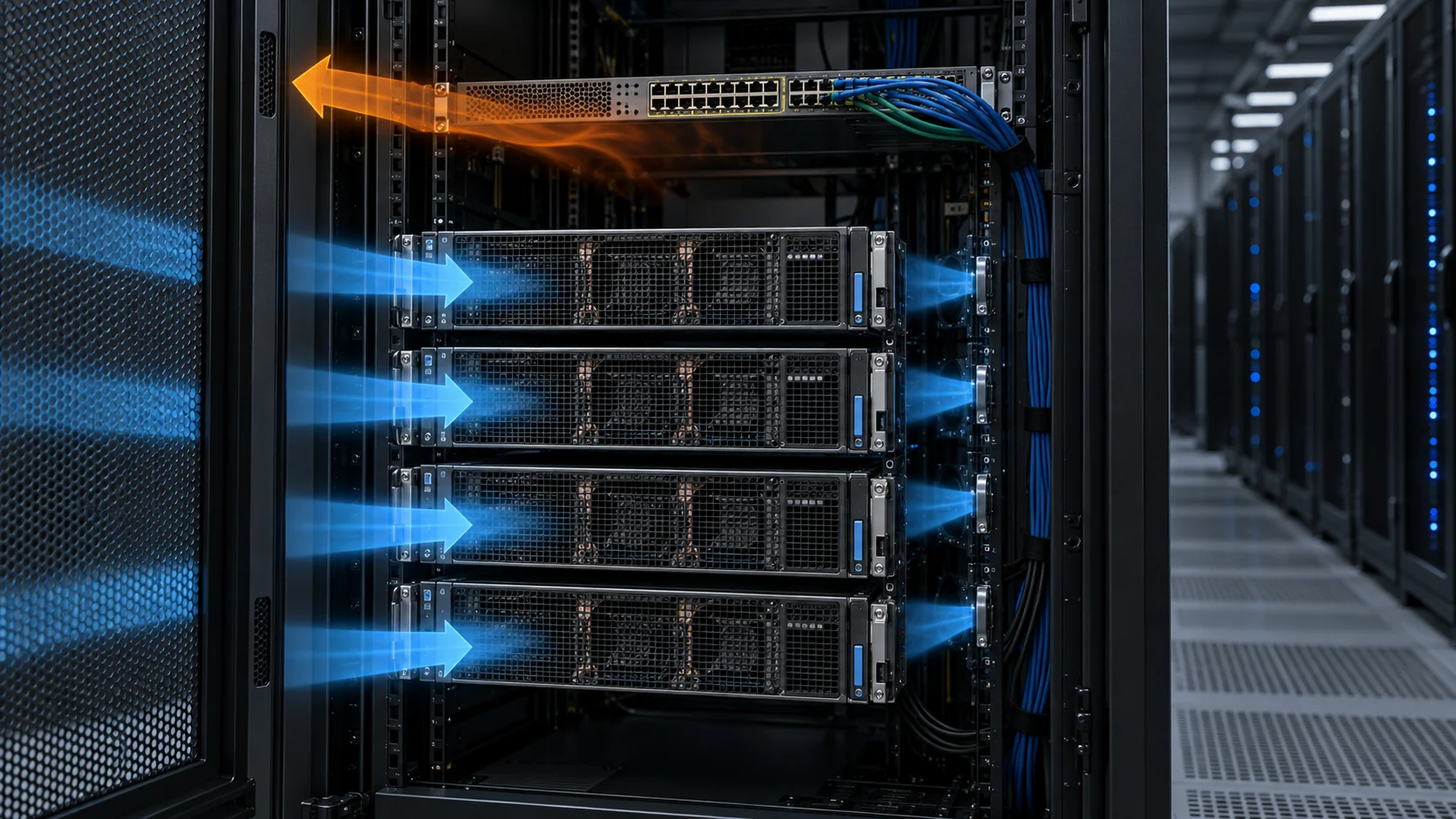
Useful airflow crosses the equipment from inlet to exhaust and removes heat from the intended components. Bypass airflow moves from a supply plenum or cold aisle directly to a return path without crossing the IT load. Recirculation airflow brings hot exhaust back to an equipment inlet. The three flows can coexist, and a total airflow meter upstream of the cooling unit may not distinguish them.
Containment changes the pressure that drives the unwanted paths. If the cold aisle is too positive, air can escape through doors, cable penetrations and rack gaps. If it is too negative, hot air can be drawn through gaps around doors or from the hot aisle. If the hot aisle is over-pressurized, it can force hot air through rack seams and the upper portion of the equipment. The correct direction and pressure band depend on the architecture, but the pressure must be measured rather than assumed.
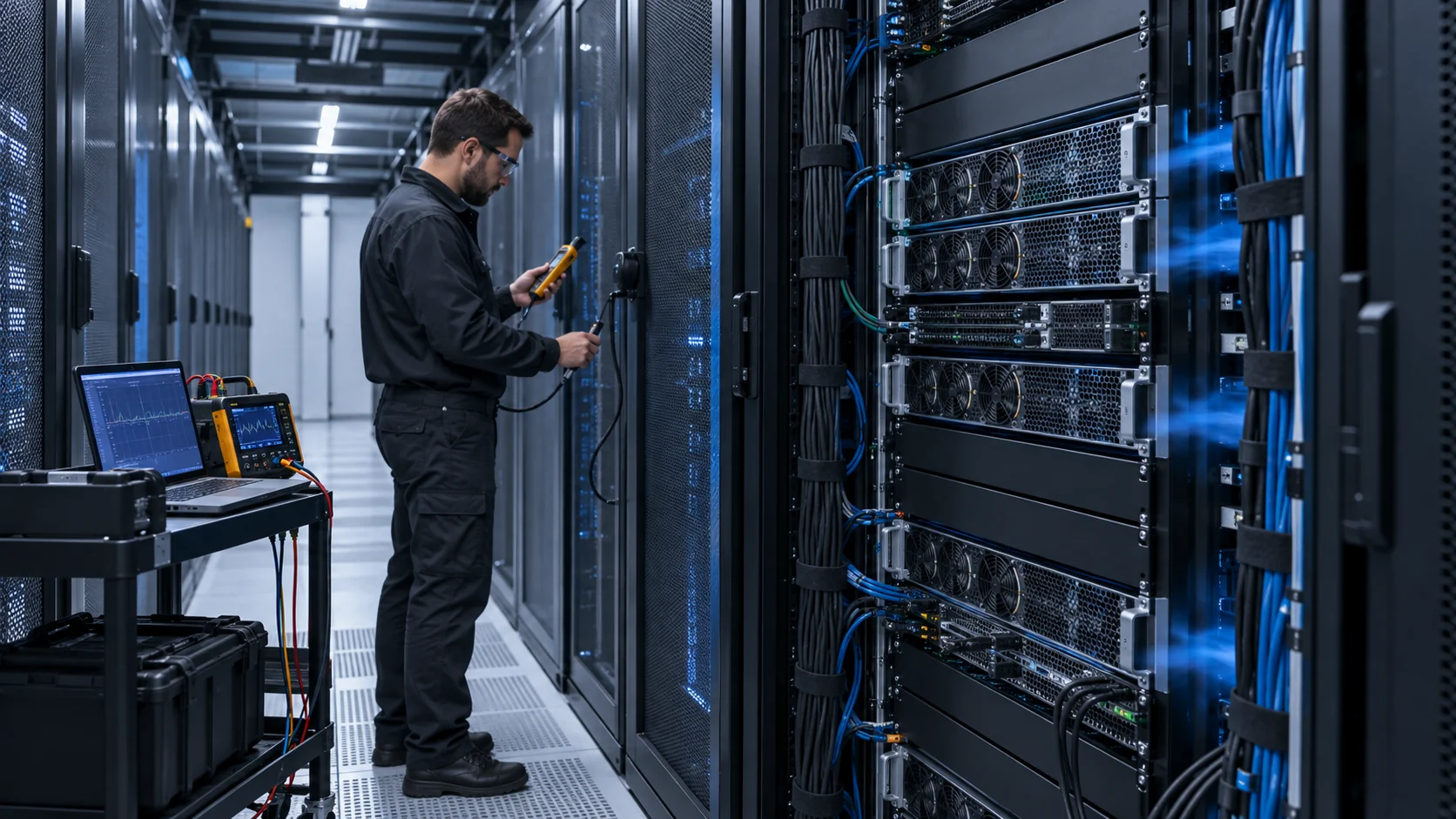
Use a pressure map with points at the first, middle and last rack, plus the containment entrance, return path and representative cabinet inlet. Add smoke visualization or tracer testing where permitted. The objective is not to create a dramatic picture; it is to find whether the same fan command produces a different airflow state at different rack positions.
| State | Where the air goes | Useful measurement |
|---|---|---|
| Useful equipment flow | Through server, GPU or storage airflow path | Rack inlet pressure, flow proxy, component temperature and exhaust temperature |
| Bypass flow | Around racks, through open tiles, gaps, curtains or cable openings | Containment pressure, leakage survey and supply/return temperature balance |
| Recirculation | From hot exhaust back to an equipment inlet | Top/middle/bottom inlet temperature map and smoke or tracer observation |
| Reverse or cross-flow | Through an idle fan, open module or wrong rack orientation | Fan status, direction, pressure differential and failed-module test |
Animated Model: More Fan Pressure Can Create More Leakage
The moving particles show the qualitative relationship between rack pressure, useful flow and bypass leakage; they are not a CFD result.
In the balanced panel, the cold aisle has enough pressure to feed the rack inlets, but leakage remains controlled. In the over-pressurized panel, the same facility fan adds pressure that escapes through a door gap and cable opening. The room fan power rises while the hottest rack does not receive proportional cooling. The visual is deliberately simple: it reminds the reviewer that pressure is a means of delivering airflow, not the airflow itself.
A useful commissioning trace pairs pressure with a flow or thermal proxy. If pressure rises but the far-rack inlet temperature does not improve, investigate bypass, rack seals, missing blanking panels and uneven floor distribution before increasing fan speed again.

Rack Pressure Is a Distribution Variable, Not a Universal Number
A pressure value is meaningful only when the measurement plane, reference point and rack state are documented.
Pressure inside a cold aisle can be measured relative to the surrounding room, a hot aisle or a return plenum. The same numeric value can describe different physical conditions depending on the reference. A sensor close to a fan discharge may read a local jet, while a sensor at the far rack may show the pressure available to the equipment. Put the measurement point on the drawing and keep it unchanged during the comparison.
For a first field survey, measure the difference at the front of the first, middle and last rack, then repeat near the top and bottom of the rack face. Compare the gradient with server inlet temperatures and fan telemetry. A large pressure drop along the row suggests distribution resistance or leakage. A small pressure difference with a large temperature spread suggests recirculation, uneven equipment flow or a heat-load concentration rather than simply insufficient room CFM.
Do not make a pressure target universal across every data hall. Rack geometry, tile arrangement, containment design, server fan control and the allowable inlet-temperature band determine the useful range. The acceptance criterion should be performance based: every critical rack receives its required airflow and remains within its thermal limit at the defined fan duty.
A Worked Airflow Example: Average Flow Can Hide the Far Rack
A simple distribution model shows why the row average is not enough for an AI cluster.
Assume a four-rack AI row needs 2,000 m3/h per rack at the selected workload, so the useful target is 8,000 m3/h. The facility fan wall delivers 9,200 m3/h measured upstream. A commissioning survey finds 2,500 m3/h at rack one, 2,300 at rack two, 2,100 at rack three and only 1,600 at rack four. The average is 2,125 m3/h, apparently above the target, but the far rack is 20% below the required flow.
The missing 800 m3/h is not automatically solved by raising the fan wall speed. The team should first check whether 1,200 m3/h is bypassing the racks through open floor areas, containment gaps or a return shortcut. If the bypass is corrected and the same upstream delivery is redistributed, the far rack may recover without a proportional fan-power increase. If the row pressure then becomes insufficient, the fan operating point can be adjusted with evidence.
This example uses a project estimate, not a universal data-center value. Its purpose is to define the measurement method: record each rack, calculate the minimum and maximum, and report useful equipment flow separately from total facility flow.
Containment Leakage Changes Fan Selection and Control
The fan does not know whether it is overcoming rack resistance or pushing air through an unintended opening.
Every containment assembly has a leakage characteristic. Doors, curtains, cable brushes, rack side panels and floor penetrations behave like parallel paths. When pressure rises, the leakage flow can increase rapidly. That changes the system curve seen by the facility fan and can consume the pressure margin that the rack inlets need. A pressure-control loop may respond by increasing speed, which creates more leakage and forms a costly feedback cycle.
A useful test closes one leakage path at a time. Temporarily seal or correct the known gap, repeat the pressure and flow measurement, and compare fan power. Missing blanking panels are especially important at the rack level because they allow hot exhaust or cold supply to bypass the intended equipment path. The test should also record the effect on the server fan command; a facility-side improvement that forces internal server fans to speed up is not a complete improvement.
The fan supplier needs the assembled resistance, not only the target room airflow. Provide fan-wall geometry, number of modules, damper state, filter or coil data, duct transitions, pressure measurement plane and the failed-module condition. For a rack fan or blower, provide the chassis grille, heat sink, cable layout and blanking state. The same principle applies at both scales.
Recirculation: The Upper Rack Is Often the First Warning
Hot air can reach an inlet through the top of a rack even when the average cold-aisle temperature looks acceptable.
ENERGY STAR notes that hot exhaust can flow over the top of servers and raise inlet temperature at the upper portion of a rack. A temperature sensor located at aisle height can miss that condition. Measure the top, middle and bottom inlet points at the most heavily loaded racks and compare them with the exhaust path. If the top inlet is warmer, inspect the containment roof, rack top, cable tray and return-air path before increasing all fan speeds.
Recirculation also appears when a rack is not front-to-back. A reverse-facing server, a missing door, an open side panel or an idle fan module can become a shortcut between hot and cold regions. The correct response may be a physical correction, a damper or a fan-direction change rather than a higher command.
For AI systems, local GPU heat load makes this more important. A rack can pass a room-average test while one accelerator group operates near its limit. Use workload maps with thermal maps, not just one inlet sensor and one facility return temperature.
Control the Least-Satisfied Rack, Then Check Fan Noise and Life
A stable control loop should protect the worst rack without forcing every fan to run at the worst-case speed forever.
A useful control strategy can use the highest inlet temperature, the lowest rack pressure or a saturation signal from the least-satisfied zone. The control should include hysteresis, rate limits and a defined minimum speed. Otherwise small pressure fluctuations can create fan hunting, tonal noise and repeated starts. ASHRAE describes zone-based control as a way to adjust fans to component needs; the practical extension is to make the zone representative of the hardest-to-cool rack.
When the containment system changes, retune the control. A new roof, door seal or fan-wall damper alters the response. Record the pressure step, fan command, rack airflow and temperature settling time. If the fan reaches the maximum command before the worst rack recovers, the problem may be a distribution bottleneck or system effect rather than an undersized motor.
Noise and life belong in the same review. A fan running near full speed continuously may meet temperature but miss the acoustic target or shorten the expected service life. A fan that cycles around its minimum stable speed may be quieter on average but create an annoying tone and additional bearing duty. Validate the installed operating distribution, not only a single maximum-RPM point.
A Commissioning Case: Fix the Gap Before Changing the Fan
The fastest thermal improvement can be a containment correction that lets the existing fan work on the intended path.
Consider an anonymized AI retrofit where the first rack row met the room-average airflow target but the last two racks showed higher inlet temperatures. The facility team increased fan-wall speed and saw a small improvement, but power and noise increased sharply. A smoke test then showed blue supply air escaping through an unsealed cable opening above the row and hot air entering around a missing rack blanking panel.
The team sealed the cable opening, installed the missing blanking panel and repeated the pressure map. At the same fan command, the far-rack pressure increased and the inlet-temperature spread narrowed. The final validation still included a higher-speed step for the maximum workload, but the base setpoint was not raised to compensate for a leakage path. The result was recorded as a before-and-after pressure, airflow, temperature and fan-power table rather than an unsupported percentage claim.
The transferable lesson is simple: if a fan is asked to overcome a hole, changing the fan can hide the installation defect and increase energy use. Measure the air path first, then decide whether the fan, the containment or both need to change.
Pressure and Leakage Test Protocol for a New Containment Layout
The test should isolate whether the fan, the distribution path or the containment itself is limiting the worst rack.
Begin with the installation in its as-balanced condition: final rack population, final blanking panels, doors, curtains, floor tiles, return path, damper positions and sensor locations. Record fan commands, fan watts, pressure at the first and last rack, inlet temperatures at the top and bottom of the critical racks, and the workload that produces the heat map. Photograph or mark any temporary opening so it is not mistaken for the production state.
Run a low, nominal and high airflow point. At each point, wait for the pressure and temperature traces to settle, then record the minimum and maximum rack values rather than only the average. If the far rack is below its useful flow while the first rack has excess flow, adjust distribution or leakage before increasing total supply. A control loop that satisfies only the nearest rack can hide a layout fault.
Next perform a leakage challenge. Close or seal one known gap at a time, such as a cable brush, door edge, missing blanking panel or open floor tile. Repeat the pressure map and compare fan power. The change in useful rack flow per watt is more informative than a single pressure reading. If sealing a gap lowers fan power while preserving the far-rack temperature, it belongs in the permanent installation requirement.
Finally test the transient and degraded states: an AI workload step, one cooling module unavailable, a service door open for the defined maintenance condition and the filter or coil at its allowed resistance. Save the command, pressure, rack flow proxy, temperature and alarm traces. The acceptance record should identify which limit failed first and whether the corrective action belongs to containment, fan selection, control tuning or workload placement.
Do not erase the baseline after the correction. Keep the before and after maps with the same sensor locations and workload so the team can quantify the effect of the change. If the containment pressure is controlled by a remote fan wall, retain the fan operating point and controller mode as part of the record; otherwise a later retuning can make a physical improvement look like a software improvement.
For procurement, this test also defines what a fan supplier needs. The supplier can size a custom fan against the measured chassis or rack restriction, but cannot infer the leakage pattern from a room-level CFM value. A short pressure-flow table, final installation drawing and representative harness or controller interface will usually produce a better sample than a request for the largest available fan. It also gives the purchasing team a fair comparison: same pressure, same flow, same density, same control state and the same evidence at the farthest rack during release. That evidence makes later design changes auditable and keeps fan, rack and facility teams aligned during production handoff now.
| Phase | Change one thing | Decision |
|---|---|---|
| As-balanced baseline | Final doors, panels, tiles and fan settings | Establish rack-by-rack pressure and temperature map |
| Steady-state sweep | Low, nominal and high fan commands | Find minimum stable point that satisfies the worst rack |
| Leakage challenge | Seal or open one known path at a time | Quantify useful-flow improvement and fan-power change |
| Power step | Apply representative AI workload transition | Check pressure recovery, thermal peak and control lag |
| Degraded state | One module out or maintenance opening | Verify remaining margin and alarm response |
What MEGA Tech Can Validate for AI Rack Airflow
We help match the fan to the actual chassis or rack operating point and support samples in the customer's installation.
We can provide custom DC axial fans, compact blowers and backward-curved centrifugal fans for server chassis, rack modules and defined air-side cooling paths. We review airflow and static pressure at the installed point, voltage, PWM or analog control, FG/RD feedback, connector, acoustic target, envelope and duty cycle. Samples can be evaluated with the final grille, heat sink, filter, cable routing and containment condition.
Send the heat load or component loss, required airflow and static pressure at that airflow, density basis, rack or chassis pressure measurement plane, containment state, leakage or blanking condition, voltage tolerance, control curve, feedback requirements, noise target, quantity and life assumption. For a fan wall, include module count, spacing, failed-module state and reverse-flow behavior.
We do not supply the data-center room, containment, CRAH, CDU, chilled-water loop, BMS or PUE guarantee unless a separate verified scope says otherwise. Our role is to make the fan and installed air path measurable, support custom samples and compare alternatives by validated performance rather than by a maximum-CFM headline.
Engineer FAQ: Containment, Pressure and Bypass Airflow
Short answers for facility, rack and thermal engineers.
Q: Is higher cold-aisle pressure always better? A: No. Higher pressure can increase leakage through doors, cable openings and rack gaps. Use the lowest pressure that satisfies the least-cool rack and validate the complete path.
Q: Why can average airflow pass while the far rack overheats? A: Flow distribution may be uneven or part of the measured flow may bypass the equipment. Measure rack-by-rack useful flow, pressure and inlet temperature.
Q: Do blanking panels really affect fan selection? A: Yes. An open U-space or side gap can create a lower-resistance recirculation path that changes the rack system curve and reduces useful flow through the heat load.
Q: Should the fan wall be controlled by room temperature? A: Room temperature alone may miss rack-level pressure starvation or a top-of-rack recirculation hotspot. Use representative pressure and temperature signals from the least-satisfied zone.
Q: What should be tested after adding containment? A: Pressure map, rack airflow or calibrated proxy, top/middle/bottom inlet temperature, fan power, server fan response, leakage state and a power-step response.
Q: What should a custom fan supplier receive? A: Airflow and static pressure at that airflow, density, installed restrictions, voltage, control, feedback, connector, noise, environment, quantity and life assumption.
Questions for a Design Review
Use these questions before approving a containment or fan change.
- Where is the pressure measured, what is the reference point and does the sensor represent the farthest rack?
- What fraction of total facility airflow is useful equipment flow versus bypass or leakage?
- Have top, middle and bottom inlet temperatures been measured at the most heavily loaded racks?
- Are doors, curtains, cable penetrations, blanking panels and floor tiles included in the system resistance?
- Does a higher fan command improve the worst rack or only increase leakage and room airflow?
- What happens when one fan module is unavailable or an idle module becomes a reverse-flow opening?
- What fan power, noise, server-fan response and thermal margin remain at the lowest stable pressure setpoint?
- What exact information will be sent to the supplier for a custom rack or chassis fan sample?