Filtration Is an Airflow Design Problem
A HEPA or carbon filter cannot perform as specified if the fan, filter frame and enclosure leak are treated as separate accessories.
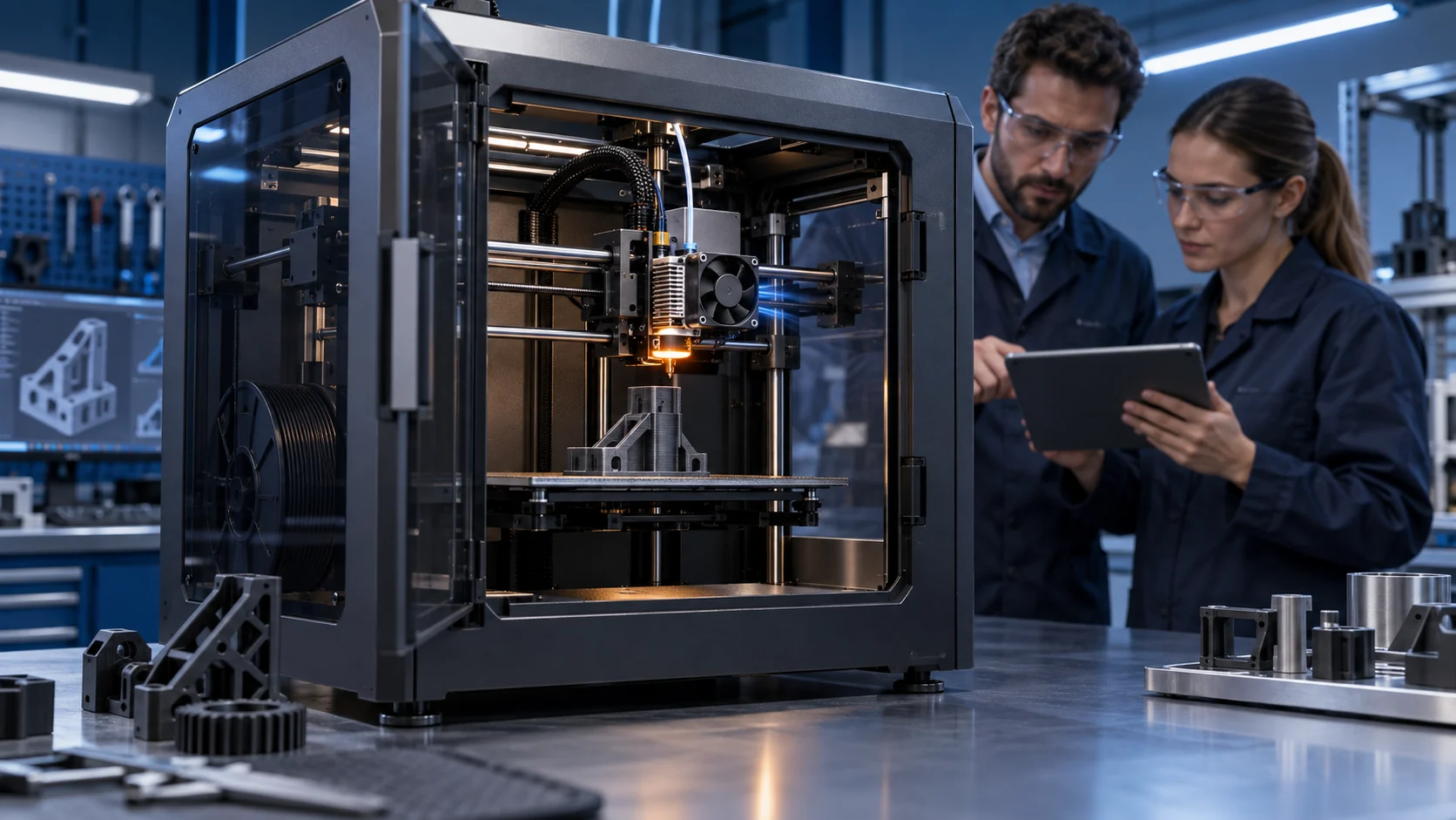
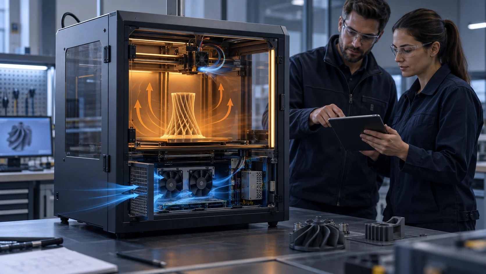
Enclosed 3D printers create a difficult cooling and air-quality compromise. The chamber must often retain heat for engineering materials, while the operator may want particles and chemical vapors captured rather than released into the room. A filtration fan therefore has two jobs: create a controlled pressure path through the filter and preserve the print environment while it does so. Selecting by free-air CFM alone answers neither question.
Prusa's current filtration guidance distinguishes an integrated filtration fan from a DIY filter that uses existing printer fans. It also states a minimum power setting for effective whole-chamber filtration on its own platform and recommends post-print filtration. Those are product-specific controls, not universal values for every printer. The transferable engineering lesson is that filter area, pressure drop, fan duty, chamber temperature and post-print time must be specified together.
UltiMaker describes an inside-out airflow arrangement for its Air Manager and reports that its tested result depends on filter type, particle size and concentration rather than on one universal percentage. That is why a credible printer design needs a defined sampling method and a defined filter condition. A fan can be spinning, the filter can be present and the chamber can still have a bypass path that weakens the intended result.
This article gives thermal engineers, printer OEMs and fan purchasers a practical selection method. The examples are illustrative planning values, not universal emission limits, filtration efficiencies or MEGA product ratings. Replace them with the selected filter curve, enclosure geometry, material process, local regulations and the acceptance test for the machine.
Separate Particle Capture, Vapor Control and Chamber Cooling
A filter label does not define the whole air-quality or thermal function.
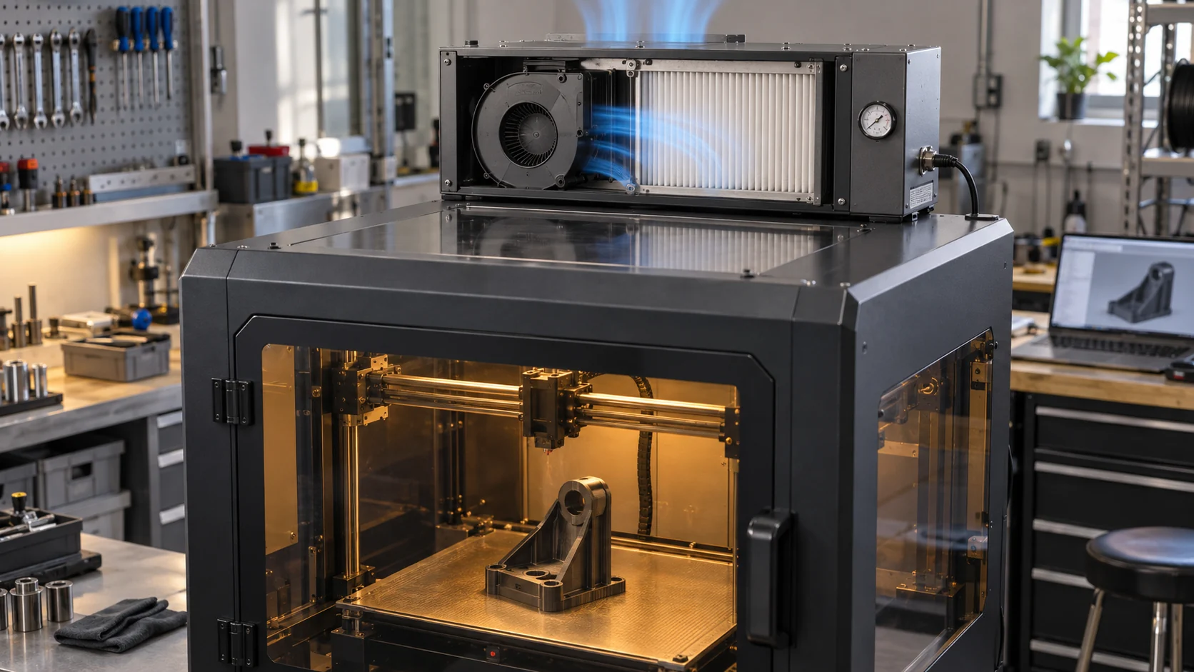
HEPA or EPA media and activated carbon address different parts of the air problem. Prusa's filtration glossary describes a combined system with a HEPA stage for ultrafine particles and activated carbon for chemical vapors. That combination does not mean every filter has the same efficiency, life or pressure drop. The media, face area, pleat geometry, sealing, airflow and test method all belong in the specification.
The chamber cooling function is also distinct. A filter fan that runs too hard can pull the chamber temperature down, change warping behavior or disturb the material process. A fan that runs too slowly may not move air through the media or may leave a stagnant region near the build plate. The controller should therefore understand the thermal state and the filtration state instead of treating the fan as a fixed-speed appliance.
For a first design review, write three contracts: the particle-control contract, the vapor-control contract and the chamber-temperature contract. Each contract should name the air volume, target condition, sensor or measurement, filter stage, fan command and service state. If the printer only needs post-print filtration, keep that mode separate from active-print chamber control and document how the chamber temperature is protected in both modes.
Do not claim a health or compliance result from a fan selection. A fan supplier can help deliver the required pressure and flow through a defined filter assembly; the printer manufacturer must define the material risk assessment, filter qualification, sampling plan, workplace controls and final compliance.
| Function | What the fan must do | Evidence to keep |
|---|---|---|
| Particle stage | Move chamber air through the specified media and prevent bypass | Filter type, face velocity, pressure, leak check and measured air path |
| Vapor stage | Provide contact time and flow through the specified sorbent | Media specification, service state and chemical test boundary |
| Chamber control | Hold the material process temperature while filtration operates | Chamber sensor, fan command, inlet temperature and print result |
| Post-print mode | Continue controlled extraction or recirculation after the print | Duration, speed, filter state and cool-down record |
| Service state | Keep the required function as media resistance increases | Clean and loaded pressure-flow points plus replacement trigger |
Calculate a First Airflow Target, Then Add Filter Pressure
Start with the chamber exchange or filtration objective, but select the fan at the installed pressure point.
A useful first estimate for an enclosure is Q = n x V, where V is chamber volume and n is the chosen air-change rate per hour. Suppose a printer chamber is 0.18 m3 and the design review starts with 4 air changes per hour for a controlled post-print recirculation mode. The estimate is 0.72 m3/h, or about 0.42 CFM. That number is only a volumetric starting point; it says nothing about distribution, filter face velocity, capture efficiency or the pressure required to move through the media.
Now consider a different requirement: the filter module must circulate 18 CFM through a large media panel to sweep the chamber evenly without a dead pocket. If the clean filter contributes 65 Pa, the carbon stage 35 Pa, the inlet and outlet 22 Pa and the duct 18 Pa, the clean path is about 140 Pa. If the loaded filter reaches 110 Pa, the service path is about 185 Pa. A fan that is attractive at 18 CFM and 65 Pa may be unsuitable at 18 CFM and 185 Pa.
The point of the two examples is not to prescribe 0.42 CFM or 18 CFM. It is to keep the requested airflow tied to a reason and to a pressure condition. For filtration, face velocity and residence time can matter as much as total chamber flow. For chamber control, distribution and temperature stability can matter more than the headline exchange rate. State which requirement controls the selection.
Use the measured or supplier filter curve and plot it with the fan P-Q curve. If the intersection sits near shutoff, the filter module may be noisy, inefficient or sensitive to service loading. If the intersection sits at free delivery, the fan may be oversized and the controller may have no useful low-speed resolution. The target is a stable, measurable installed duty with margin for the defined service state.

Select the Filter Before You Select the Blower
Media area, pressure drop, sealing and service life determine whether the fan can deliver a repeatable result.
A filter should be specified with its rated airflow, initial pressure drop, expected final pressure drop, test method, efficiency boundary and replacement condition. A large pleated filter can lower face velocity and pressure drop, while a small cartridge may fit the machine better but require a higher-pressure blower. Neither is automatically better. The correct choice depends on available area, acceptable noise, service access, material process and the required filtration mode.
The frame is part of the filter. A gasket that compresses unevenly, a warped printed bracket or a service door that leaves a gap can create a parallel path. The fan may then show a lower differential pressure than expected while emissions bypass the media. Inspect the frame under vibration and thermal expansion, and use a safe tracer or leak-check method where the site procedure permits it.
The filter also changes with time. Dust loading can increase pressure, carbon can become saturated, and a damaged pleat can reduce the intended boundary. Define what triggers service: hours, pressure, a filter-use counter, a measured performance change or a material-specific maintenance plan. Prusa's current product guidance includes filter-use tracking and a change-filter action on its platform; other printers need their own implementation and validation.
Do not use one filter number as a substitute for a complete service condition. Record filter part, media lot when relevant, clean pressure, loaded pressure, fan command, airflow or pressure at duty, chamber temperature and post-print response. That record lets the fan supplier assess whether a new sample needs more pressure, a different wheel, a larger frame or a different control floor.
| Input | Why the fan supplier needs it | Typical evidence |
|---|---|---|
| Filter type and media | Sets the intended particle or vapor function | Supplier datasheet and test boundary |
| Clean pressure drop | Defines the initial operating point | Pressure at the stated airflow |
| Final or service pressure | Defines the required margin | Replacement threshold or loaded curve |
| Face area and seal | Determines velocity and bypass risk | Final bracket, gasket and leak inspection |
| Service access | Affects filter replacement and cable routing | Production drawing and maintenance procedure |
| Noise and power limit | Prevents a filtration fix from creating a product problem | Measured sound and fan watts at duty |
Interactive Model: Watch Restriction Consume Filtration Margin
Change path restriction, fan command, chamber temperature and filter load to see which combination requires a real test.
The interactive model is a qualitative screening aid. It is not a filtration-efficiency calculator, a CFD result or a substitute for particle and vapor testing. Use it to make the test matrix visible: the same fan command can have a different installed airflow when the filter loads, and the same airflow can have a different thermal effect when the chamber inlet is already warm.
Move the controls one at a time, then combine them. A design that looks comfortable in the reference state may lose margin when the filter is loaded and the chamber is hot. The acceptance test should then state the required airflow or pressure, the filter condition, the fan control, the chamber temperature and the measured result at the protected location.
Control Filtration Without Destroying Print Quality
The filtration fan is part of the thermal controller, not an independent vacuum pump.
During printing, the fan can change chamber temperature, pressure and local airflow. A sudden speed step may cool the chamber or disturb the part, especially when the enclosure is small and the exhaust opening is close to the build volume. A controller should define minimum operating speed, ramp behavior, upper limit, sensor location and what happens if the fan feedback is missing. The values must be tuned on the machine and material process, not copied from a different printer.
Prusa's current filtration documentation states that its filtration fan interacts with chamber temperature control and that certain minimum power settings are needed for effective chamber filtration on its platform. This is useful evidence that the functions are coupled. It is not a universal 40 percent rule for other products. The general method is to find the lowest validated duty that moves the required air through the filter and maintains the approved chamber state.
Post-print filtration deserves its own state. The chamber may contain residual particles or vapors after the heater and motion system stop, while the material part may still be cooling. Define whether the fan recirculates through the filter, exhausts outdoors or uses another controlled path. Record duration, speed, filter condition, chamber temperature and the operator's access condition. Do not claim that a post-print timer alone proves a clean air result.
FG or tach feedback confirms rotor motion; it does not confirm media bypass, face velocity or particle removal. Add a pressure sensor, calibrated flow measurement or another validated proxy if the risk justifies it. A fault response should distinguish fan stopped, filter loaded, frame open and sensor unavailable, because each requires a different service action.
| State | Control question | Acceptance evidence |
|---|---|---|
| Print filtration | Does the selected duty preserve chamber process conditions? | Chamber temperature, fan command, pressure and print result |
| Minimum duty | Does the fan still move the required air at the control floor? | Start, restart and installed airflow or pressure |
| Post-print | Does filtration continue for the defined time without unsafe access? | Duration, filter state and chamber trend |
| Filter loading | Does the controller detect or plan for rising resistance? | Pressure trend, fan margin and service trigger |
| Fan fault | What happens when the fan stops or feedback disappears? | Alarm, controlled response and operator instruction |
Validate Particle and Vapor Claims at the Complete Machine
Fan testing and emissions testing answer different questions and should not be substituted for one another.
A fan manufacturer can help establish airflow, pressure, voltage, power, noise and feedback behavior. A filtration or air-quality claim requires the complete printer, chosen material, enclosure, filter assembly, operating mode, sampling position and test method. UltiMaker's published discussion of UFP reduction makes the boundary clear: efficiency depends on particle size, nature and concentration. A result from one machine cannot be copied to another by matching the fan frame.
For an engineering validation, keep the air-path test and the emissions test linked but separate. First prove that the expected air crosses the filter at the defined clean and loaded states. Then run the appropriate particle or chemical sampling method for the material and environment. If the pressure result changes after the filter ages, repeat or bound the emissions result accordingly. The fan's normal RPM must remain a supporting signal, not the only pass criterion.
Sampling location changes the conclusion. A sensor at the filter outlet does not tell you the operator exposure at the front of the machine, and a chamber sensor does not prove the filter sees all of the emitted air. Define whether the test is measuring chamber concentration, outlet concentration, room concentration, leakage or another specific quantity. Document door state, print phase, material, nozzle temperature, chamber temperature and post-print interval.
MEGA Tech can help make the fan-side evidence repeatable: the installed pressure-flow point, the connector and control behavior, the fan current, the start and restart response and the thermal condition. The printer team owns the emissions test plan and the final safety or compliance claim.
Use a Representative Service Scenario
A filter system becomes production-ready when its clean, loaded and failed states are all understandable to service staff.
Consider an anonymous enclosed printer prototype used for ASA and nylon in a small engineering workshop. The team wanted to keep the chamber warm during printing and run a post-print filtration cycle. The initial filter module had a compact fan, a narrow media cartridge and a printed frame. It moved air on the bench, but the installed chamber test showed an uneven sweep and the measured pressure was lower than expected.
The review did not immediately order a stronger fan. The team checked the filter seal, the blower direction, the inlet area, the discharge location and the pressure taps. A gap at the frame allowed a parallel path around part of the media, so the measured differential pressure understated the restriction seen by the intended flow route. The bracket was revised, the media area and service access were documented, and the test was repeated with a controlled loaded condition.
MEGA Tech then reviewed the required pressure and airflow at the revised path, the voltage and control interface, the acceptable noise, the small first-build quantity and the warm chamber condition. A sample fan or blower was accepted only after the machine record included pressure, command, current, feedback, chamber temperature and the filter state. The result is a method for selecting the next sample, not a claim that one fan size is universal.
This scenario is anonymous and illustrative. It is not a named customer result, a filtration certification or a guaranteed percentage reduction. Its value is the sequence: define the claim, seal the path, measure the installed duty, test the service condition and keep the emissions or compliance conclusion within the test evidence.
How MEGA Tech Can Support a Filtration Fan Sample
The useful fan sample is built around the filter curve, enclosure path and declared service state.
MEGA Tech develops custom DC cooling fans and compact centrifugal blowers for installed pressure and airflow requirements. For a 3D printer filtration module, customization may involve the fan frame or thickness, blower outlet, connector and cable length, PWM or voltage response, FG or RD feedback, bearing configuration, mounting detail, pressure target, noise limit or replacement compatibility. The sample is selected from the complete path rather than from a free-air CFM headline.
For a first review, provide the chamber volume, intended material and process temperatures, filter media and curve, clean and loaded pressure, target airflow or face velocity, filter area, frame and gasket drawing, duct geometry, available fan envelope, supply voltage and tolerance at the connector, control and feedback interface, noise limit, duty cycle, life assumption and first-build quantity. If a current system exists, send its fan part number, measured operating condition and the failure or maintenance record.
We can support a small first build for a new printer, a replacement fan or blower matched to an existing module, or a production-oriented variant after the installed sample is validated. We can also compare an axial path with a centrifugal path when the filter, duct and outlet create different pressure requirements. The final printer remains the acceptance fixture.
Our boundary is deliberate. MEGA Tech supplies and customizes cooling fans and samples; we do not supply filter media, the printer controller, firmware, fume extraction concept, emissions certification, fire protection or final compliance approval. The printer maker owns those system decisions and must validate the complete machine.
Recommended Fan Starting Points
These catalogue series may be suitable starting points for this application. Final selection depends on the installed airflow, static pressure, voltage, noise target and operating environment.
Request a sample for validation on your equipment.
Engineer FAQ: 3D Printer Filtration Fans
Use these questions before freezing the filter module or the fan interface.
Q: Is maximum CFM enough to select a filtration fan? A: No. Use the installed airflow or face-velocity requirement at the clean and loaded filter pressure. A fan's free-air value does not include the filter, frame, duct or outlet.
Q: Does a HEPA label prove the printer is safe? A: No. The complete media, seal, fan, enclosure and test method must be validated for the material and operating condition. Safety and compliance remain system-level decisions.
Q: Should the filter fan exhaust outside the printer? A: It depends on the air-quality and chamber architecture. Internal recirculation can be valid for a defined filter system; external exhaust requires its own duct, back pressure, discharge and building assessment. Do not assume one architecture fits every machine.
Q: Why can a loaded filter show a lower pressure than expected? A: The filter frame or service panel may be bypassing the media, the pressure taps may be in the wrong plane or the fan operating point may have changed. Inspect the path before adding fan speed.
Q: Should filtration run during printing or only afterward? A: The answer depends on material, enclosure, chamber temperature and the validated air-quality strategy. Test print filtration and post-print filtration as separate control states.
Q: Can FG feedback prove the filter is working? A: No. FG indicates rotor speed. Pair it with pressure, airflow or a validated proxy and the filter service state.
Q: What can MEGA Tech customize? A: Fan or blower type, frame or thickness, pressure and airflow duty, connector, cable, PWM, FG/RD behavior and mounting details can be reviewed around the machine requirement.
Questions for a Filtration Design Review
Bring these questions to the meeting that approves the printer enclosure, filter and fan.
- Which materials trigger filtration, and what particle or vapor function is being claimed?
- Is the filter stage HEPA/EPA, activated carbon or a combination, and what test boundary supports the claim?
- What are the clean and loaded pressure drops at the required airflow or face velocity?
- Where are the pressure taps, and how has bypass around the filter frame been excluded?
- What chamber temperature and print-quality limit must the filtration fan preserve?
- What is the minimum validated fan command, connector voltage and restart behavior?
- How does the controller detect fan stop, filter loading, open frame and unavailable sensor data?
- What is the post-print filtration duration, and what operator-access condition applies during it?
- Which test proves airflow, which test proves filtration performance and which team owns the final compliance decision?