The SiC Inverter Passed the Bench Test but Lost Margin in the Vehicle Enclosure
An anonymised EV power-electronics team needed a cooling fan for a compact silicon-carbide inverter with high heat flux, a restrictive air path and a narrow packaging envelope.
The first thermal check used an exposed heat sink, a clean inlet and a temporary fan bracket. The result looked comfortable on the bench. After the inverter was installed, the air path included an inlet grille, a cable harness, a short bend, a cover and a compact outlet. The heat sink still received air, but not the same useful airflow that the free-air fan number suggested. During a repeated high-load sequence, the baseplate and nearby gate-driver region approached their thermal limit sooner than expected. The gap between the two results was the reason to review the complete installed path.
The natural proposal was to select a larger fan or increase speed. That could increase noise, current and mechanical stress without proving that more air would cross the SiC heat sink. The engineering question became more specific: what airflow and static pressure are required at the installed operating point, under the hot-inlet and low-voltage conditions that the vehicle actually presents?
The customer, vehicle platform and measured acceptance values remain confidential. This case describes a fan-side engineering workflow, not an automotive certification claim or a universal SiC thermal guarantee. The vehicle developer and system integrators retain responsibility for the complete inverter, electrical safety, EMC, functional safety and qualification program.
Define the SiC Heat States Before Choosing the Fan
A silicon-carbide inverter can move between short high-power events, sustained charging and hot-soak recovery, so one average heat number is not enough.
The design review separated traction, regenerative braking, charging, standby and post-load cool-down. Each state had a different combination of switching loss, conduction loss, gate-driver heat, capacitor heat and ambient condition. The team identified the component or heat-sink location that actually defined the limit. This prevented a low average enclosure temperature from hiding a short local excursion at the power module.
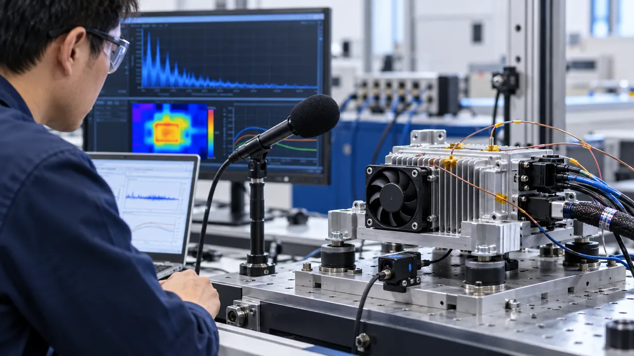
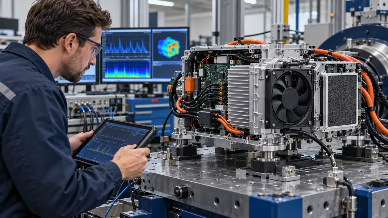
Sensors were placed at the fan inlet, heat-sink base, power module reference point, gate-driver region and outlet. Fan voltage, current, command, actual RPM and FG/RD feedback were logged with the thermal channels. A synchronized record showed whether a temperature rise followed electrical load, hot inlet air, a PWM transition, a blocked path or a loss of useful airflow.
The initial target was written as a testable boundary rather than a marketing number. It stated the heat state, inlet condition, allowable temperature margin, measurement location and enclosure configuration. Assumptions were marked separately from measured values so that the candidate fan would not be approved simply because a clean bench result looked persuasive.
| Input | Why it matters | Evidence to record |
|---|---|---|
| Power state | Switching and conduction losses change with duty | Time-aligned electrical and thermal trace |
| Hot inlet | Reduces available temperature difference | Sensor position and inlet basis |
| Installed resistance | Sets the fan operating point | Grille, bend, heat sink and outlet pressure |
| Control interface | Changes start, speed and fault behavior | Voltage, PWM, RPM and FG/RD trace |
| Thermal decision point | Avoids approving on the wrong temperature | Power-module or heat-sink acceptance location |
Build the Air-Path Pressure Budget Around the Heat Sink
The fan is only useful when its delivered airflow reaches the SiC heat sink at the installed pressure.
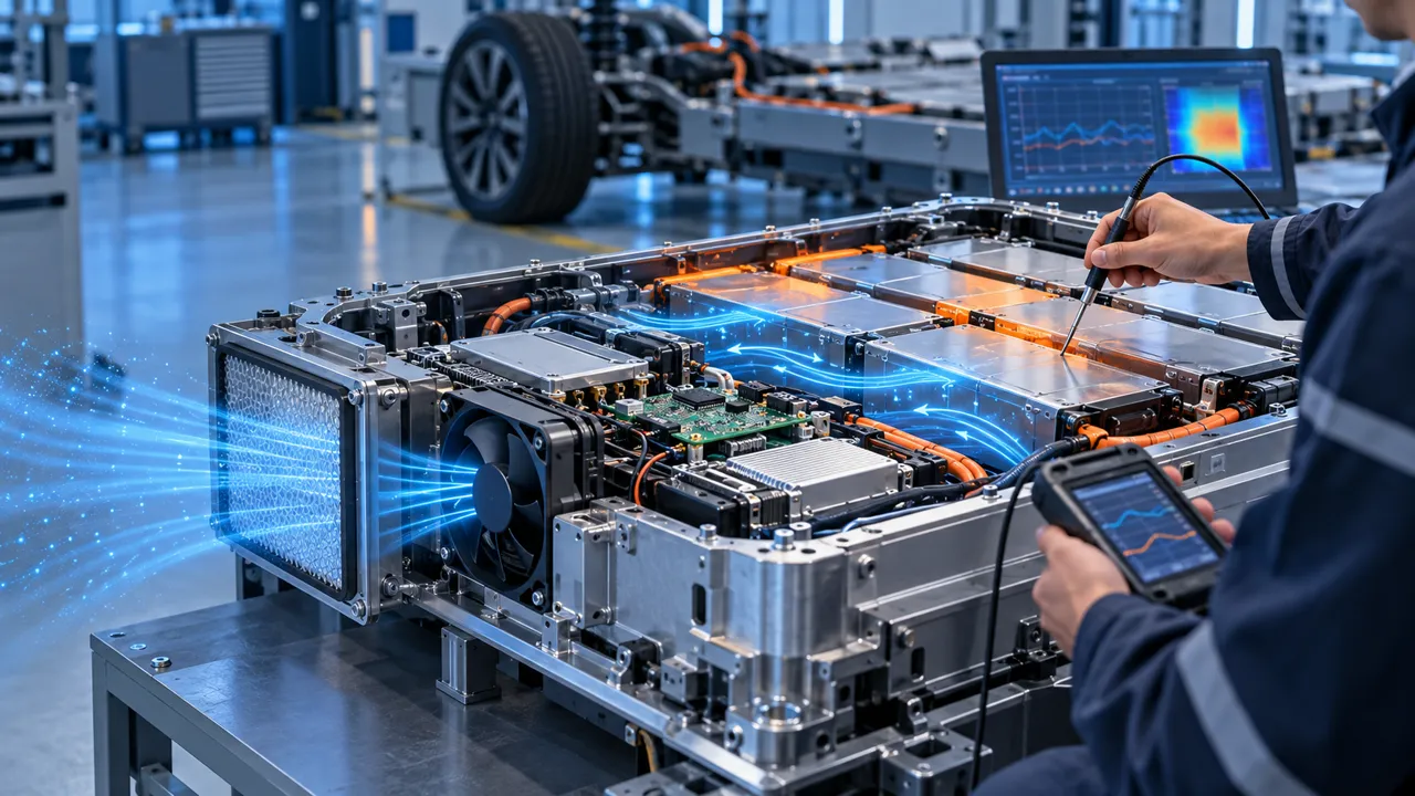
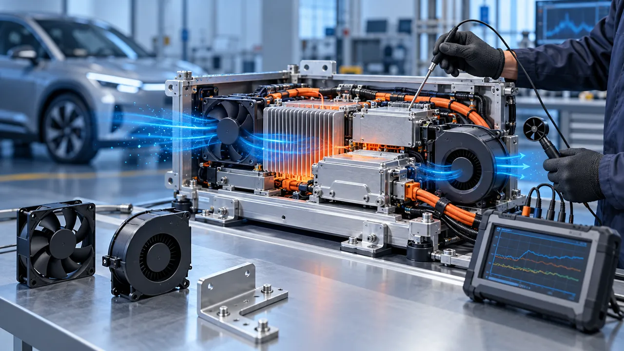
The team mapped the path from vehicle-side inlet to grille, filter or mesh, fan, bend, heat sink and outlet. It marked every section where pressure could be lost or where hot discharge air could return to the inlet. The cable harness was included because a bundle can reduce a narrow opening or create a bypass around the heat sink. The pressure budget was reviewed before comparing fan families.
A free-air airflow value was treated as a reference point, not as the installed result. Candidate P-Q behavior was compared with the resistance of the actual enclosure. The intersection moved when the grille changed, the heat sink became denser or the outlet seal was compressed. A compact centrifugal blower could be considered when the path required a sharp turn, while a high-static-pressure axial fan could fit a short straight path. The final decision depended on measured pressure and useful airflow, not on outline size alone.
The team also stated where pressure was measured. Pressure across the fan, across the heat sink and across the complete enclosure are different boundaries. Naming the boundary prevented the supplier curve, system pressure drop and vehicle acceptance result from being mixed into one unexplained number.

Check High Switching Activity Without Blaming the Fan for Every Hotspot
SiC efficiency can reduce some losses while increasing power density, edge speed and the importance of local thermal paths.
The review did not treat the fan as a replacement for the power module thermal interface. The team checked the heat-spreader contact, thermal interface material, clamping condition and heat-sink orientation before asking for additional airflow. More fan speed cannot repair a poor thermal path between the device and the heat sink. Conversely, a good interface can still fail if the installed airflow is low at the pressure created by the cover and grille.
The electrical team also recorded the switching and control states that coincided with the hotspot. A fan command transition can occur at the same time as a load step, making the acoustic or thermal response difficult to interpret. The test therefore changed one variable at a time where possible: load, inlet temperature, fan command, grille condition or mounting state. This made the next sample or air-path change defensible.
Any electromagnetic interaction was kept within the customer's system validation boundary. The fan-side review recorded the control interface, grounding arrangement and harness routing, but did not claim to replace vehicle EMC testing. The useful outcome was a clear list of fan-side and enclosure-side variables for the integrator to validate together.
Select Voltage, PWM and Feedback for the Real Harness
A fan that meets the airflow target can still fail if its control and supply behavior do not match the inverter harness.
The candidate review captured the supply range at the fan connector rather than only the nominal battery voltage. Harness resistance, protection devices and transient behavior can reduce the voltage available during startup. The team measured current and actual RPM at the connector while the inverter controller applied its intended PWM reference. PWM percentage was not treated as a universal RPM or airflow value.
Low-speed start, steady operation, command changes and high-temperature restart were tested. The record showed whether the fan reached a valid speed within the system's allowed window and whether the feedback signal became valid at the expected time. FG or RD feedback helped the vehicle controller identify a fan-side state, but the vehicle software still owned the response to a missing signal.
The control schedule was reviewed for hunting. If a temperature sensor moved around its threshold, repeated speed changes could create audible modulation, current variation and unstable thermal behavior. A defined hysteresis or stable control band was considered together with the fan's pressure margin. The objective was a predictable installed operating point, not the highest possible RPM.
| Check | Risk if missed | Pilot evidence |
|---|---|---|
| Connector voltage | Fan starts below the intended operating point | Voltage and current at the fan |
| PWM reference | Command is interpreted differently by the sample | Reference, duty and RPM trace |
| FG/RD feedback | Controller reports a false healthy or failed state | Signal timing and system response |
| Hysteresis | Fan hunts around a thermal threshold | Temperature, command and acoustic trace |
| Restart | Cooling recovery is delayed after interruption | Start timing and thermal recovery |
Validate Hot Inlet, Altitude and Thermal Cycling
The same fan and command can produce a different margin when inlet temperature, air density and duty cycle change.
The customer defined the warmest expected inlet condition for the inverter enclosure and separated it from the room-temperature laboratory condition. Hot air reduces the temperature difference available for heat rejection. Altitude changes air density and can alter the relationship between volume flow, pressure and mass flow. The record therefore stated the environmental basis instead of hiding it inside a generic operating-temperature label.
Thermal cycling included repeated high-load and cool-down states. The team watched for a condition in which the fan remained at a normal RPM while the useful airflow fell because of recirculation, filter loading or a changed seal. It also checked whether mechanical clearances, cable retention and mounting preload changed after heating.
The result was not converted into a universal derating promise. It was used to identify the conditions that the customer's sample and system qualification needed to reproduce. If the final vehicle package changes the inlet, outlet, heat source or harness, the operating point must be reviewed again even when the selected fan frame remains the same.
Keep Vibration, Noise and Mechanical Clearance in the Same Review
High-density power electronics leave little room for a fan mount, harness loop or acoustic interface to move without consequences.
The fan was installed with the intended bracket, fastener preload, gasket, guard and cable route. The team checked that mounting did not distort the frame or close the inlet. It also looked for a cable bridge across an isolator, contact with a cover and a discharge path that could excite a panel. These details can change pressure, vibration and sound at the same time.
Noise was measured at a defined position and operating state, while airflow, pressure, RPM and temperature were recorded. A lower sound level was not accepted if it came from reduced useful cooling. Tonal noise during PWM transitions was separated from broadband airflow noise and from structure-borne vibration. This avoided changing the fan when the dominant problem was a bracket or enclosure resonance.
The customer retained ownership of the vehicle vibration profile and complete qualification. MEGA Tech can review fan-side mounting, connector and cable-exit constraints and prepare a sample direction, but the final bracket, EMC, functional safety and vehicle acceptance remain with the system owner.
| Detail | Failure if missed | Evidence |
|---|---|---|
| Frame support | Distortion changes clearance or airflow | Installed fit and preload check |
| Cable exit | Harness transmits vibration or blocks inlet | Retention and clearance record |
| Panel interface | Tone or vibration is amplified | Spectrum and mounting comparison |
| Outlet seal | Hot air returns to the inlet | Flow-path or smoke check |
| Noise point | Results cannot be compared | Defined microphone position and state |
Repeat Low-Voltage Start, Power Interruption and Fault Recovery
A production fan sample must recover predictably when the inverter harness and controller do not behave like a laboratory supply.
The electrical sequence included the lower supply tolerance, cold start, hot restart, short power interruption and repeated start. Current and feedback timing were recorded at the fan connector. A delayed feedback signal can look like a failed fan to the inverter controller, while a harness voltage drop can look like a motor-start problem. The separate traces helped the team identify which layer required correction.
The thermal sequence repeated the high-load transition that created the original hotspot. The team recorded time to valid speed, time to useful airflow and temperature recovery after a brief interruption. A fan that restarts electrically but takes too long to move useful air may still fail the system requirement.
Fault response stayed at the vehicle-system boundary. The fan manufacturer can provide fan-side data and sample evidence. The vehicle team must define whether a missing FG/RD signal causes a warning, power limit, charging stop, controlled shutdown or service action.
Freeze the Fan Specification Around the Installed SiC Duty
The release record must make the tested boundary repeatable for pilot assembly, service replacement and later platform changes.
The final record captured fan envelope, voltage tolerance, current, installed airflow and static pressure, control interface, connector, mounting, noise target, temperature, altitude basis and environment. It also identified the thermal acceptance point and the sensor position used for the decision. The P-Q reference was kept separate from the measured system result so later readers could see what was catalogue information and what was installed evidence.
Change triggers were listed before pilot production: a new grille, heat sink, thermal interface, cover, duct, cable route, controller schedule, connector, bracket, ambient range or service orientation. Each can move the operating point or create a new acoustic or vibration path. The same outline dimensions do not prove equivalent cooling.
Service replacement was considered as part of the design. A replacement fan should not require a different cable route, distort the frame or disturb a seal. If a voltage variant, connector or control behavior changes any of those details, the request returns to engineering for a new sample decision rather than becoming an uncontrolled substitution.
How MEGA Tech Supports Custom SiC and Power-Electronics Fans
MEGA Tech helps equipment teams move from a high-heat-flux power-electronics requirement to a fan sample tested in the real enclosure.
MEGA Tech develops and manufactures custom cooling fans, covering fan selection, air-path review, sample validation and volume production. We can review DC axial fan and centrifugal blower candidates against airflow and static pressure at the installed operating point, with attention to voltage, PWM, FG/RD, connector, noise, vibration, mounting and environmental conditions.
For a first review, send the inverter or converter heat load by state, inlet temperature and altitude basis, required airflow and static pressure at that airflow, fan envelope, voltage tolerance, control interface, connector, mounting, noise and vibration target, environment, quantity and life assumption. A pressure-drop sketch, thermal map, current fan sample or representative enclosure makes the first review more useful.
MEGA Tech is the custom cooling-fan manufacturer. Complete vehicles, batteries, inverters, chargers, coils, liquid loops, controllers, electrical safety, EMC, functional safety and automotive qualification remain with the vehicle developer and system integrators. Start with the fan selection tool, review the DC axial fan range, or request a sample on WhatsApp.
Engineer FAQ
These questions usually decide whether a SiC inverter fan sample is ready for the next design review.
Q: Is free-air CFM enough for a SiC inverter? A: No. The installed grille, heat sink, bend, cover and outlet create the actual pressure point.
Q: Does a larger fan automatically provide more thermal margin? A: No. Check envelope, pressure, control, current, recirculation and useful airflow at the heat sink.
Q: Can PWM duty define the cooling result? A: No. Record actual RPM, airflow, pressure and temperature at the supplied connector voltage.
Q: Does fan-side evidence equal automotive qualification? A: No. The vehicle developer owns complete electrical, EMC, functional-safety and platform qualification.
Q: What should I send for a custom sample? A: Send heat load, airflow, static pressure, inlet temperature, envelope, voltage, control, connector, mount, noise, vibration, environment and quantity.
Questions for a SiC Inverter Fan Design Review
Use this checklist with thermal, electrical, mechanical, controls, manufacturing and service teams.
- Which inverter, charger or converter state defines the limiting heat load?
- What airflow and static pressure are required at the installed heat sink and outlet?
- Where are the fan inlet, power module, heat sink and outlet temperatures measured?
- What connector voltage exists during startup, hot restart and power interruption?
- What PWM, FG/RD or alarm behavior defines a valid fan state?
- Can the grille, cover, harness or outlet create bypass, contact or hot-air recirculation?
- What switching or load transition must be separated from a fan-control transition?
- What noise and vibration measurement point represents the installed vehicle module?
- Which change triggers a new sample: heat sink, duct, grille, cover, controller, cable or mount?
- What exact information should accompany the sample request: size, voltage, airflow, pressure, quantity and environment?