The BMS Bay Had Airflow but No Stable Margin
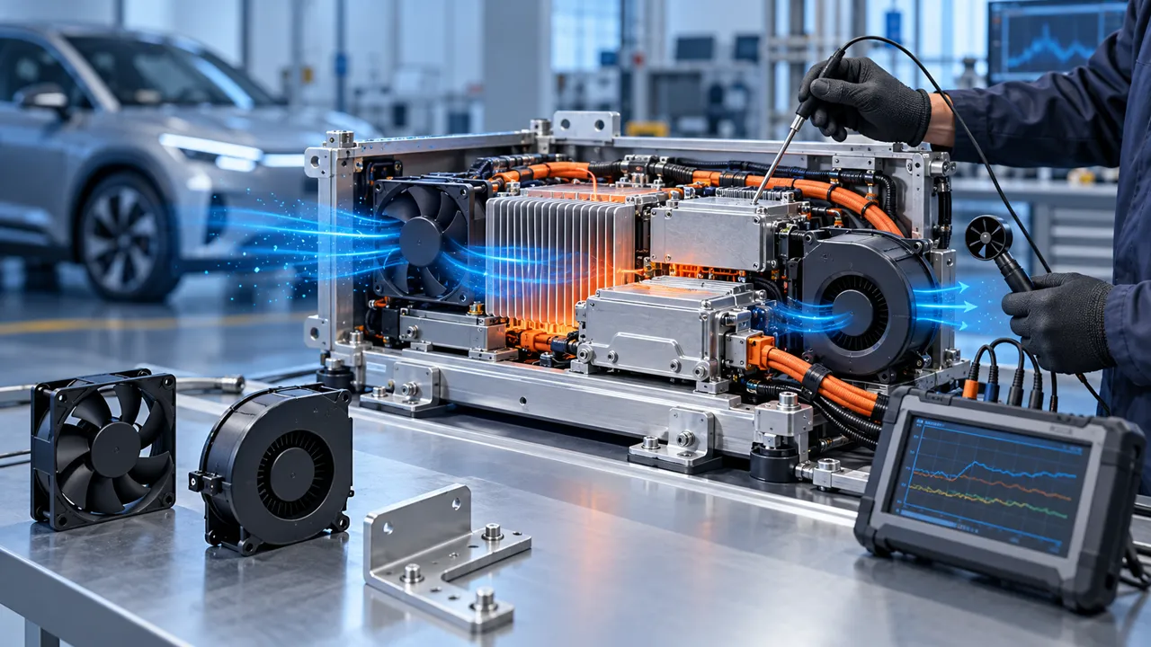
An anonymised EV battery-pack team needed a compact cooling fan for BMS electronics, contactors and service electronics inside a low-clearance enclosure.
The pack passed an open-bench electronics test, but the installed BMS bay had a filter, cable bundles, covers and a narrow outlet. During repeated charging and hot-soak conditions, the BMS board temperature rose while the fan still reported a normal speed. A later inspection found that part of the inlet flow bypassed the board and that condensation risk changed the acceptable operating sequence.
The engineering question was not whether the pack had a fan. It was whether the fan delivered useful air at the BMS heat source, at the real pressure and temperature, without creating a path for moisture or interfering with battery service. Fan selection, enclosure airflow, harness routing and fault feedback had to be reviewed together.
Customer identity and measured acceptance values remain confidential. This case describes fan-side selection and installed validation; it is not a battery-safety, thermal-runaway or vehicle-certification claim.
Separate Battery Heat From BMS Electronics Heat
The BMS board can have a different limiting condition from the battery cells and contactor area.
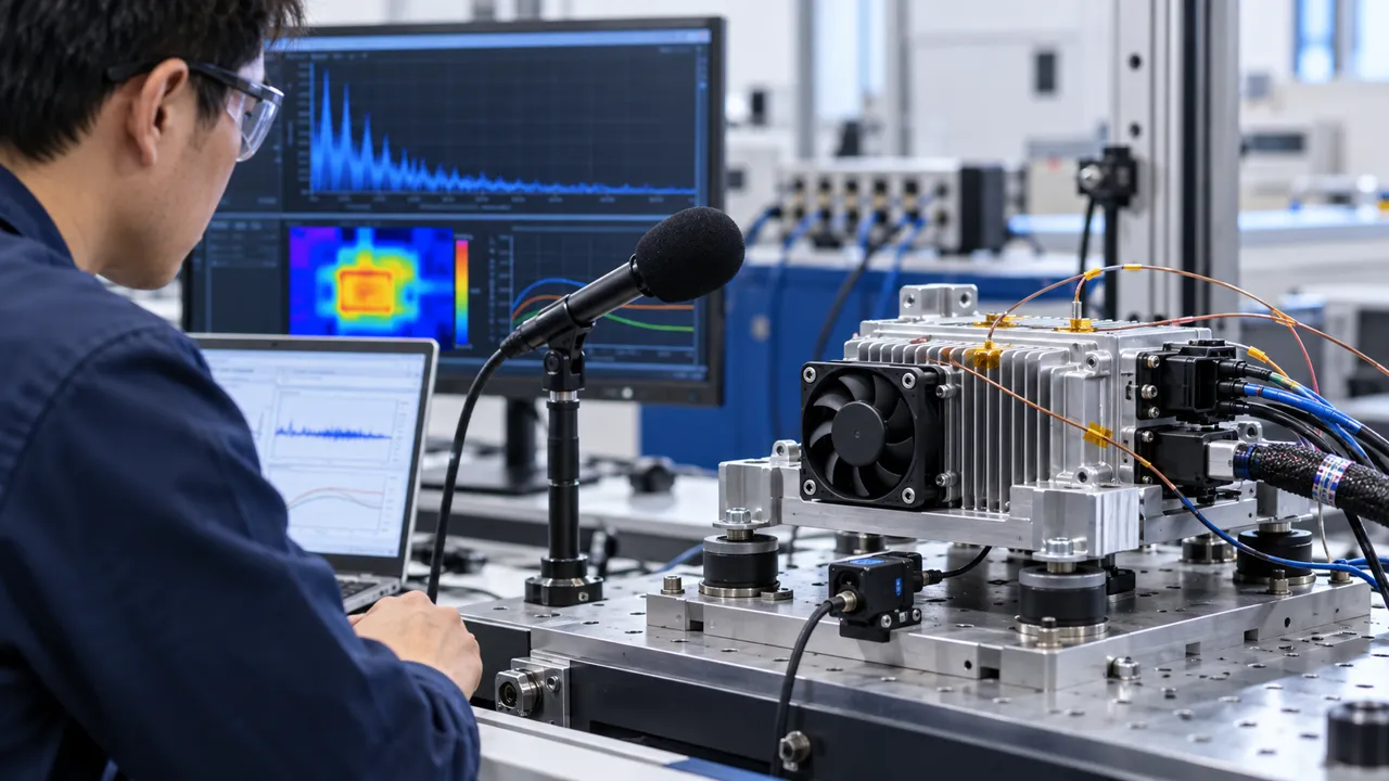
The review mapped the cell modules, busbars, contactors, BMS board, communications electronics and fan inlet. Sensors were placed at the BMS hotspot, inlet, outlet, enclosure wall and nearby battery surface. Current, voltage, fan command, speed feedback and pressure were logged with the temperature channels.
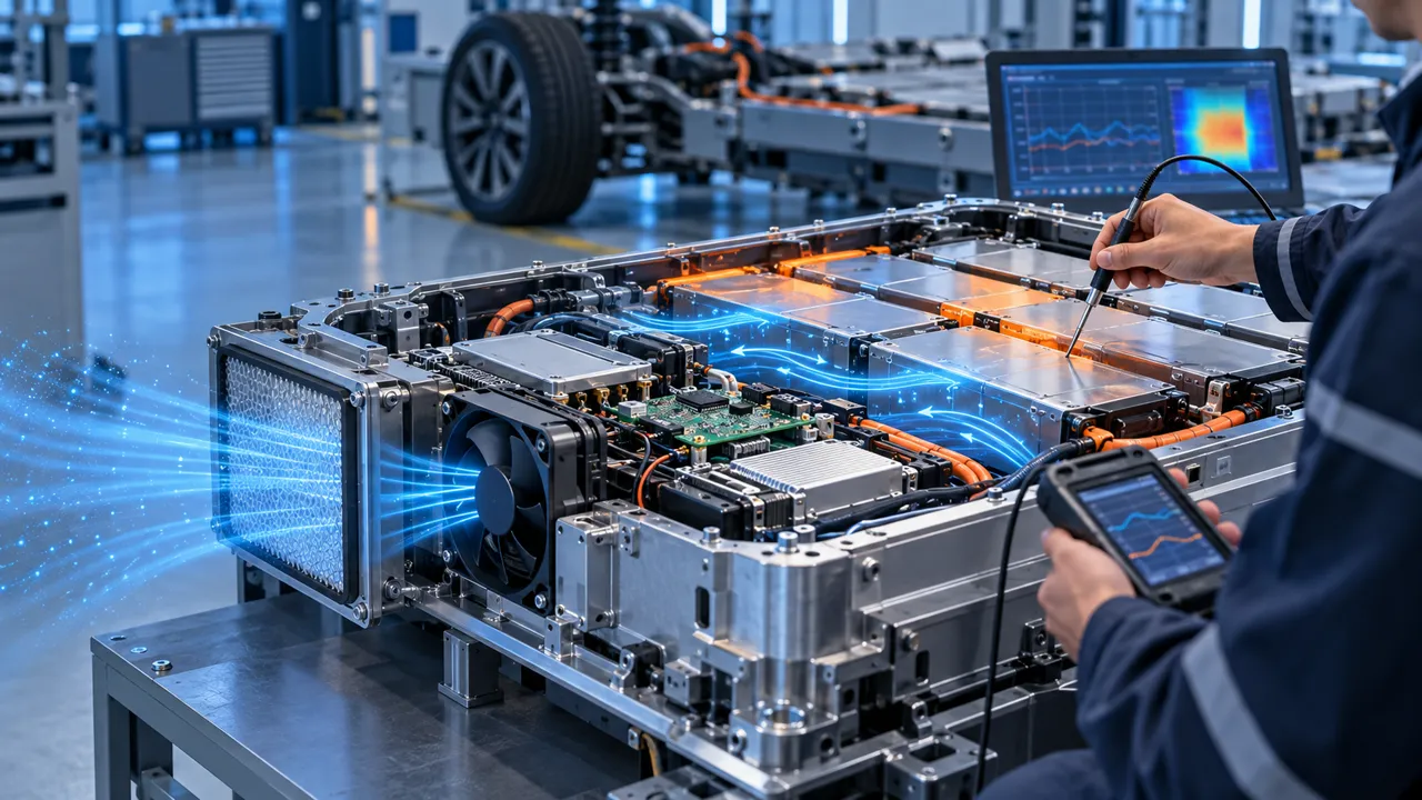
A lower average enclosure temperature did not prove the BMS board was cooled. Air could short-circuit around the board or leave through a service gap. The team therefore measured airflow near the heat source and checked the pressure created by the filter, grille, standoffs and outlet.
This separation also prevented an unsafe conclusion. A cooling fan does not remove the need for the pack owner to define cell temperature, electrical isolation, moisture protection, service procedure and thermal-event response.
| Measurement | What it reveals | Evidence |
|---|---|---|
| BMS hotspot | Local electronics margin | Sensor location and load trace |
| Inlet temperature | Available cooling basis | Inlet and enclosure condition |
| Installed pressure | Fan operating point | Pressure taps and restriction list |
| Moisture state | Condensation risk | Dew-point and enclosure observation |
| Feedback | Fan-side health | FG/RD trace and controller action |
Select the Fan at the Filtered Operating Point
The candidate was compared with the filter and outlet installed, not by free-air airflow alone.
A battery pack enclosure can have a modest airflow requirement and still need pressure margin because the filter, grille and narrow channels resist flow. The team compared compact axial and centrifugal candidates against the installed resistance. The selection included frame, thickness, voltage, current, PWM, FG/RD, connector, noise and the available service space.
A fan with a larger nominal CFM was not automatically better. If its outlet created recirculation or its current reduced the pack energy budget, it was a poor candidate. The correct sample was the one that delivered useful air at the BMS board while preserving the enclosure and service boundaries.
The operating point was recorded with the actual cover, filter, cable bundle and outlet. Any change to those parts was treated as a new pressure and temperature input rather than a cosmetic mechanical change.

Review Condensation Before Raising Fan Speed
More airflow can change surface temperatures, but it does not automatically remove condensation risk.
The enclosure team identified cold surfaces, service openings, pressure equalization and the air source. The fan inlet condition was recorded together with humidity or dew-point assumptions. A cold battery enclosure can have a different moisture risk from a warm electronics bay, especially after a vehicle is parked and then energized.
The fan path was checked for drawing humid air directly across a cold surface or forcing moisture toward a connector. The design review also considered filter wetting, drain paths, sealing and service access. MEGA Tech can review the fan-side flow and sample, but moisture protection and battery enclosure safety belong to the pack integrator.
The acceptance record stated the environmental basis. It did not use a generic IP or condensation claim without a verified product and enclosure test.
Validate Low Voltage, Sleep Wake and Restart
A BMS cooling fan may be controlled by a vehicle or pack state machine rather than a simple always-on switch.
The test included the supply tolerance, sleep state, wake command, low-speed request, brief power interruption and hot restart. Voltage was measured at the fan connector with the real harness. Time to valid feedback, startup current, actual speed and airflow development were recorded.
The controller needed a defined minimum command. A low PWM value that saves energy but stalls the fan is not a valid sleep strategy. The team also checked whether a delayed FG/RD signal created a false alarm during wake-up and whether the controller could distinguish a fan fault from a disconnected harness.
The vehicle or pack controller decided whether a fault generated a warning, service request, BMS power limit or another action. The fan supplier provided interface evidence; it did not own battery protection or vehicle safety logic.
Check Vibration, Service Clearance and Cable Routing
A battery-pack fan must keep its air path and connector behavior after assembly and service.
The mount, fastener preload, isolator, cable supports and connector latch were reviewed. The harness could not bridge a vibration isolator, touch the fan guard or close the inlet. Service access was checked so a technician could remove the filter or cover without pulling the fan connector or changing the standoff position.
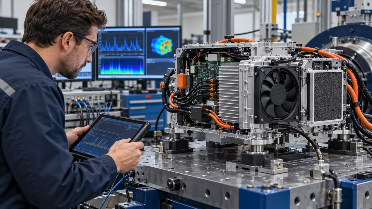
Vibration was applied with the representative pack fixture. The fan was monitored for current, speed, feedback, noise, movement and contact. After the sequence, the airflow and BMS temperature test was repeated. This linked mechanical durability to thermal performance instead of treating them as separate paperwork.
MEGA Tech can adjust the fan-side mounting, connector and cable exit around the customer enclosure. The pack owner remains responsible for road-load vibration, electrical isolation, service safety and pack qualification.
| Detail | Failure if missed | Evidence |
|---|---|---|
| Inlet clearance | Pressure loss or bypass | Installed flow and pressure |
| Harness route | Contact or force bridge | Clearance and retention check |
| Connector | Intermittent wake or alarm | Latch, pin and feedback test |
| Service access | Filter or fan disturbed | Repeatable service procedure |
| Mount | Vibration changes airflow | Post-test inspection and thermal repeat |
Define the Fan Fault and Thermal-Event Boundary
The fan can report a fault, but the battery system decides the safe response.
The test introduced a stopped fan, missing feedback and a disconnected harness at controlled conditions. The record included BMS temperature, fan command, pressure, current and alarm timing. This allowed the team to distinguish a fan failure from a filter restriction or sensor fault.
A fan fault is not the same as a thermal event. The pack controller and safety architecture must define what happens when electronics cooling is lost and what happens when a cell or contactor condition becomes abnormal. MEGA Tech does not supply the battery, BMS, contactors, safety controller or emergency function.
The boundary was kept in the sample report so a cooling recommendation could be used without implying pack approval or thermal-runaway protection.
Result: A BMS Fan Sample With a Defined Operating Window
The project closed when the team could connect fan pressure, airflow, moisture basis, control state and BMS temperature in one record.
The release package captured the enclosure, filter, fan envelope, voltage, current, command, feedback, installed pressure, airflow point, BMS hotspot, inlet condition, moisture assumptions, vibration state and service access. It identified which changes required a new sample: a different filter, cover, connector, harness, BMS heat load or temperature range.
The transferable result was a design-review method. The team could see whether a temperature rise came from pressure loss, bypass, moisture restriction, low-voltage startup or a controller state. That is more useful than a general “battery cooling fan” label.
A different pack has a different heat map and moisture boundary. Same size and voltage do not prove equivalent cooling, environmental life or battery safety.
How MEGA Tech Supports Custom BMS Cooling Fans
We help EV pack teams move from a BMS heat load and enclosure path to a fan sample for installed testing.
MEGA Tech develops and manufactures custom cooling fans, including DC axial fans and centrifugal blower options for restrictive paths. Our work covers fan selection, air-path review, sample validation and volume production. Selection starts from airflow and static pressure at the operating point, not a catalogue frame alone.
For a first review, send the BMS heat load, battery and inlet temperatures, airflow and pressure target, filter and grille, fan envelope, supply tolerance, PWM/FG/RD or alarm interface, connector, harness, moisture basis, vibration condition, noise target, quantity and life assumption. We can then evaluate a sample on the customer enclosure.
We do not supply complete battery packs, BMS units, cells, contactors, liquid loops, vehicle controllers or battery-safety certification. Those remain with the pack and system integrators. Start with the fan selection tool, review the DC axial fan range, or request a sample on WhatsApp.
Engineer FAQ
These questions usually decide whether a BMS fan sample needs another iteration.
Q: Does a normal fan speed prove BMS cooling? A: No. Check airflow at the BMS heat source and the pressure created by the real filter, cover and outlet.
Q: Can higher airflow remove condensation? A: Not automatically. Review dew point, cold surfaces, inlet humidity, sealing and the actual air path.
Q: Should the BMS fan run during vehicle sleep? A: It depends on pack energy, temperature, moisture and controller requirements. Validate wake and restart states.
Q: Is fan feedback a battery-safety approval? A: No. FG/RD is fan-side evidence used by the pack controller’s own safety and service logic.
Q: What does MEGA Tech need for a first sample? A: BMS heat load, airflow and pressure, temperature, moisture basis, voltage, control, envelope, vibration, quantity and service conditions.
Questions for an EV BMS Fan Design Review
Use this checklist with thermal, electrical, enclosure, controls and service teams before freezing the pack fan.
- What BMS and service-electronics heat load defines the normal and peak states?
- What airflow and static pressure are required after the real filter, grille and cover?
- What inlet temperature, humidity and dew-point basis applies during cold soak and wake?
- What voltage tolerance, sleep command and wake command reach the fan connector?
- What are the minimum start and valid FG/RD timing requirements?
- Can the harness, connector or service panel change the pressure path or create a contact risk?
- What vibration state is applied and how is the post-test airflow repeated?
- What does the pack controller do after a fan fault, filter trend or missing feedback?
- Which change triggers a new sample: BMS load, filter, cover, fan, connector, controller or moisture basis?