The E-Axle Controller Passed Bench Cooling and Failed the Contaminated Air Path
An anonymised e-Axle team needed a compact cooling fan for motor-controller electronics exposed to heat, vibration, dust and possible oil mist.
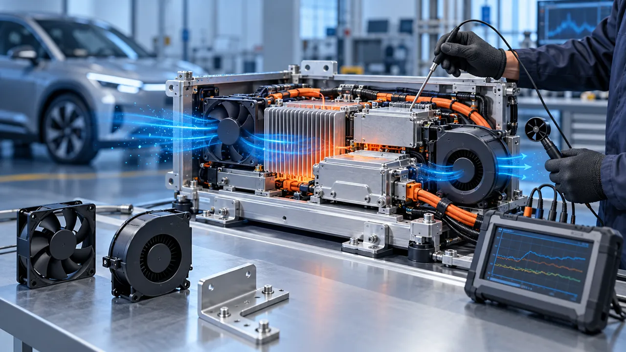
The bench test used a clean heat sink and a short open air path. The installed e-Axle module used a grille, cable harness, pressure drop, hot housing and a contamination-prone service environment. During a repeated drive-cycle sequence, the controller hotspot rose while the fan still reported a normal speed. Inspection showed that dust loading and a thin oil film could change the inlet loss and disturb the useful path through the heat sink.
The first proposal was to increase fan speed. That could raise noise, current and bearing stress without proving that the extra air reached the controller. The engineering question became: what airflow and static pressure are required at the real operating point, after contamination, temperature, mounting and vibration are included?
Customer identity and measured acceptance values remain confidential. This case describes a practical workflow for high-ambient, vibration and oil-and-dust fan validation without claiming e-Axle certification.
Separate Motor-Controller Heat From E-Axle Housing Heat
A delayed fan start can be electrical, mechanical or thermal; the test must distinguish the causes.
The review logged supply voltage at the fan connector, current, command, RPM or FG/RD feedback, inlet temperature, outlet temperature and component temperature. The same timestamp also captured vibration input and the state of the e-Axle assembly harness. This showed whether a missing pulse followed a voltage drop, a mechanical contact, a controller threshold or a genuine fan start problem.
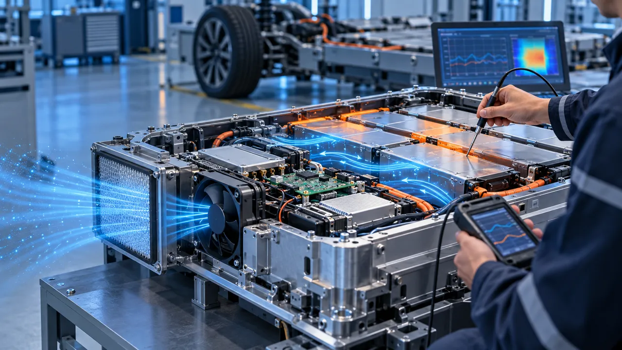
The airflow path was checked with the real grille, cover, filter, duct and cable bundle. Temperature alone could not prove useful cooling because a fan may spin while air bypasses the heat source. Pressure and airflow were measured at defined points, and the test noted whether the inlet air had already been heated by a nearby component.
The design review separated fan supplier evidence from e-Axle assembly evidence. The sample could be judged for starting, feedback, installed flow and mounting behavior; the e-Axle assembly team still had to judge its full environmental and safety requirements.
| Observation | Possible cause | Check |
|---|---|---|
| No feedback at cold start | Voltage, motor or controller threshold | Connector voltage, current and start time |
| Speed changes in vibration | Mount, harness or contact path | Fixture, clearance and RPM trace |
| Hotspot rises at normal RPM | Bypass or pressure loss | Installed flow and pressure |
| Noise changes with temperature | Bearing, mount or air path | Spectrum and temperature state |
| Intermittent alarm | Connector or feedback threshold | Harness retention and FG/RD trace |
Select the Fan Against Clean and Contaminated Resistance
The candidate was compared against the installed system curve before and after the defined dust and oil-mist exposure.
The customer defined the lowest expected supply and the oil-and-dust temperature condition. The fan was mounted with the production connector, harness length and protection components. Voltage was measured at the fan pins during startup because a supply setting at the bench does not show harness drop or connector resistance.
The test recorded time to valid speed feedback, startup current, command, airflow development and temperature recovery. Repeated starts checked whether the motor or controller behaved differently after a previous hot run. A fan that starts once is not enough evidence if the e-Axle assembly can interrupt and restore power during operation.
The low-command region was also checked. PWM percentage was not treated as a universal RPM value; actual speed and installed airflow were measured at each voltage and temperature state.

Check Hot Inlet Air, Oil Mist and Dust Loading
An e-Axle environment can move the fan operating point even when the command is unchanged.
The team defined the inlet-temperature basis for drive cycles, parked hot-soak and service restart. It also listed the contamination basis: dust source, expected deposit, oil-mist exposure, filter or grille condition and cleaning interval. The fan was not evaluated only at comfortable room temperature or with a clean inlet.
High ambient also changes the available temperature difference for cooling. The test used the customer’s temperature basis and recorded the density assumptions used in the fan and thermal comparison. A generic “high-temperature fan” statement was not accepted without an installed result.
The candidate sample was checked across the commanded speed range. Increasing speed was useful only when it increased air through the heat source without exceeding current, noise or vibration limits.
Validate Vibration, Mounting and Harness Clearance After Contamination
The fan and cable route were treated as part of the e-Axle assembly structure, not as separate laboratory items.
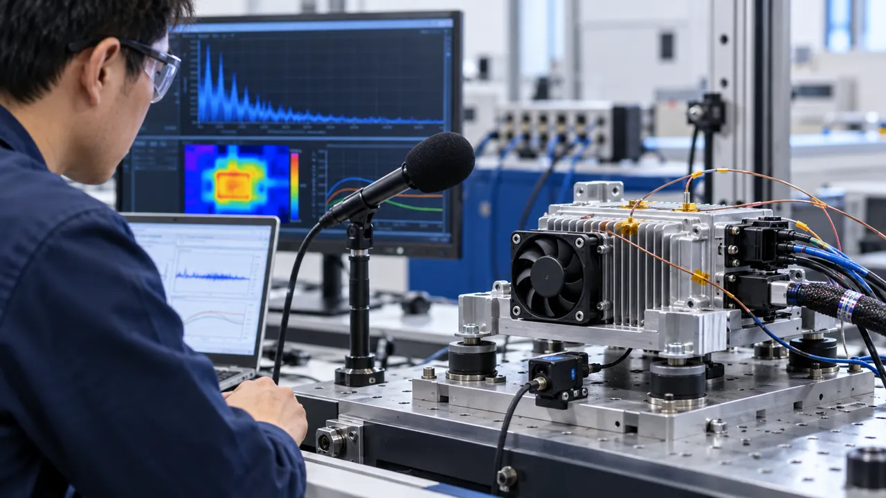
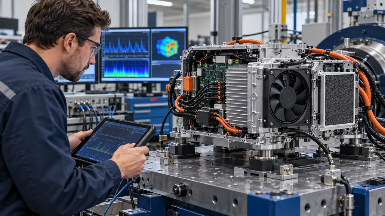
The vibration review checked the fan bracket, fastener preload, elastomer support, connector latch and harness clamp points. A cable that bridges an isolated mount can add a force path; a loose cable can contact the guard or create intermittent feedback. The production orientation and representative fixture were used for the sample run.
The test monitored RPM, current, feedback, sound, temperature and contact risk during the vibration sequence. A change in fan speed or feedback was investigated against fixture response and harness movement. The result was not reduced to a single vibration number because the e-Axle assembly profile and mounting transfer function define the installed response.
MEGA Tech can adjust the fan-side frame, connector, cable exit and mounting details around the customer assembly. The customer owns the complete e-Axle assembly bracket, road-load profile and qualification plan.
Repeat Cold Start, Hot-Soak and Restart With the Real Air Path
A fan can remain electrically healthy while a shifted grille, cable or seal changes the pressure path.
After the vibration sequence, the team repeated the airflow and pressure measurement with the cover, harness and service parts installed. The inlet and outlet were inspected for contact marks, shifted foam, loose fasteners and partial blockage. This check connected mechanical durability to thermal performance.
The design also included service variation. A replacement fan or connector should not be able to change the inlet clearance or create a bypass that the original sample did not have. The inspection points and torque method were written into the sample record so the next build could be compared with the same boundary.
The useful acceptance package therefore contained both a thermal result and a mechanical condition. A clean pressure result before vibration did not prove the same result after vibration or service access.
| Check | Record | Why it matters |
|---|---|---|
| Connector | Latch, pins and feedback | Prevents intermittent start or alarm |
| Harness | Clearance and clamp state | Avoids contact and force bypass |
| Mount | Torque and isolator condition | Keeps the installed response repeatable |
| Inlet | Grille, seal and blockage | Preserves the pressure point |
| Outlet | Recirculation and heat path | Protects the hot-ambient margin |
Inspect Bearings, Frame and Airway After the Environmental Sequence
A missing feedback signal is a system input; the e-Axle assembly controller decides the safety action.
The control test defined the expected FG or RD signal, the valid-speed window and the missing-signal delay. It also tested a loose connector, a stopped fan and a command below the reliable start region. The purpose was to avoid confusing a wiring issue with a motor issue.
The e-Axle assembly system then assigned the response: warning, power limit, service request or a controlled shutdown. MEGA Tech can provide fan-side behavior and a sample interface, but it does not decide e-Axle assembly functional safety, traction control or emergency behavior.
The release record kept these boundaries visible. It listed what the fan supplier verified and what the e-Axle assembly team still had to qualify. That makes a quotation and sample review more useful than a broad claim of e-Axle assembly readiness.
Result: A Repeatable E-Axle Fan Sample Boundary
The project closed when the team could reproduce the start, hot, vibration and airflow conditions at the customer connector and mount.
The final record captured connector voltage, current, command, RPM, feedback, inlet temperature, installed pressure, airflow point, heat-source temperature, mount, harness and vibration condition. It identified which result belonged to the fan and which result belonged to the e-Axle assembly assembly.
The transferable result was a repeatable test boundary. A future change to connector, harness, bracket, grille, controller, temperature range or duty could be assessed as a known change instead of starting with a vague “fan failed” report.
A different e-Axle assembly platform needs its own validation. Same frame size does not prove the same oil-and-dust behavior, vibration response, noise, pressure margin or environmental life.
How MEGA Tech Supports Custom E-Axle Cooling Fans
We help e-Axle and motor-controller electronics teams move from an environmental duty to a fan sample that can be measured in the real module.
MEGA Tech develops and manufactures custom cooling fans, including DC axial fans and centrifugal blower options for restrictive paths. Our work can cover fan selection, air-path review, sample validation and volume production. We select from airflow and static pressure at the operating point, not a part number or free-air CFM alone.
For a first review, send controller heat load, inlet temperature, airflow and pressure target, fan envelope, supply tolerance, PWM/FG/RD or alarm interface, connector and harness, mount, dust and oil-mist basis, noise and vibration target, environment, quantity and life assumption. We can then evaluate a sample on the customer assembly at the relevant temperature, supply and contamination states.
We do not supply complete vehicles, e-Axle units, motors, inverters, chargers, coils, liquid loops, controllers or automotive certification. Those remain with the vehicle and system integrators. Start with the fan selection tool, review the DC axial fan range, or request an e-Axle fan sample on WhatsApp.
Engineer FAQ
These questions usually decide whether an e-Axle fan sample needs another iteration.
Q: Is oil-and-dust time only a motor issue? A: No. Check connector voltage, harness drop, command threshold, controller timing and mechanical temperature state.
Q: Can a fan meet airflow after vibration? A: It must be measured after the vibration and service condition with the real grille, cover, harness and mount.
Q: Does high ambient and contamination require a bigger fan? A: Not automatically. Check heat load, inlet temperature, pressure, density, current and useful airflow at the heat source.
Q: Is FG/RD evidence e-Axle qualification? A: No. It is fan-side interface evidence that the e-Axle assembly controller uses in its own qualification.
Q: What does MEGA Tech need for a first sample? A: Envelope, voltage, airflow and pressure, temperature, vibration, control, connector, mount, quantity, noise and environmental requirements.
Questions for an E-Axle Fan Design Review
Use this checklist before freezing the fan, connector, bracket and harness.
- What are the oil-and-dust, hot-soak and high-ambient inlet conditions at the fan connector?
- What airflow and static pressure are required after the grille, cover, heat sink and outlet are installed?
- What voltage tolerance and harness drop exist during startup?
- What PWM command, actual RPM and FG/RD behavior define a valid running state?
- What vibration and shock profile is applied to the real mount and harness?
- Can the connector, cable, guard or bracket contact or create a force bypass?
- Which temperature point defines the thermal decision after vibration and service?
- What happens after missing feedback or a stopped fan: warning, limit, service or shutdown?
- Which change triggers a new sample: connector, mount, grille, controller, harness, temperature or duty?