Why Free-Air CFM Does Not Answer a Cleanroom Tool Question
The tool needs useful airflow through the intended filter and heatsink path, not a headline number measured with the outlet open.
A fan's free-air airflow is the rightmost point of a fan curve, where static pressure is close to zero. A precision tool adds resistance through the intake filter, guard, duct, cable routing, heatsink and exhaust. The operating point is where the fan curve meets that system curve. When a filter loads, the intersection moves toward lower airflow even if the fan remains at the same RPM.
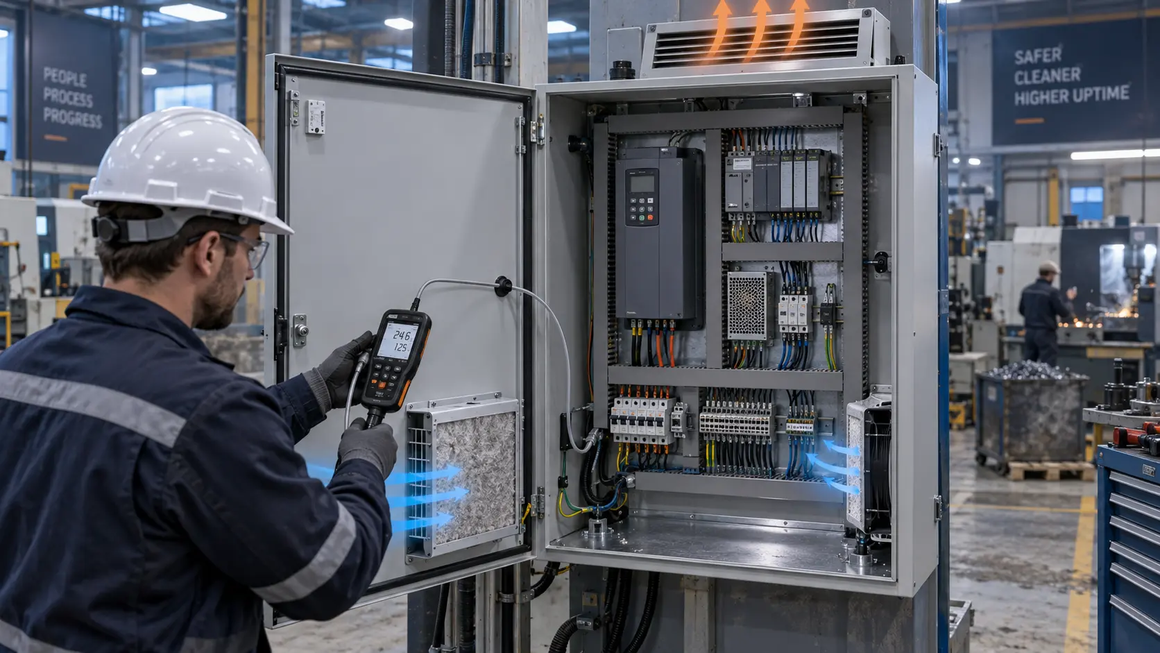
The first test therefore installed the real filter frame, seal, fan guard and downstream heatsink. Differential pressure was measured across the filter and across the complete fan assembly. The team recorded whether the pressure instrument was measuring static pressure or total pressure. This distinction matters when comparing a supplier curve to an installed measurement; otherwise a correct measurement can look like a disagreement.
The filter state was divided into clean, service-limit and blocked-intake response. The service-limit state became the selection basis. Clean-filter airflow was retained for commissioning and maintenance trending, not used as the only release number. The blocked-intake check verified that the controller could detect a dangerous state before a local component exceeded its limit.
The Engineering Hook: A Small Hotspot Can Dominate the Tool
Average enclosure temperature can look acceptable while one processor, motor drive or power converter remains too hot because the local air path is weak.
As an illustrative screening calculation, a tool electronics bay dissipating 240 W with an allowed average air rise of 12 K would need Q = 240 / (1,200 x 12) = 0.0167 m3/s, or about 35 CFM. The 1,200 J/(m3 K) heat-capacity estimate is only a screening basis. A local power module, motor amplifier or laser driver may need a directed stream at a lower temperature than the enclosure average.
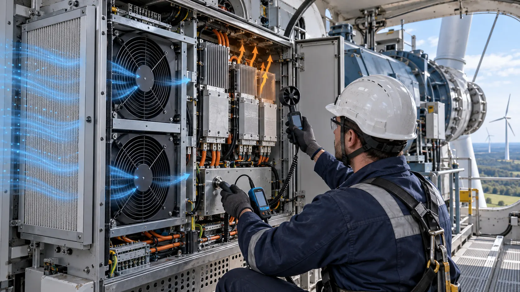
The team mapped the inlet, the air immediately upstream of the heatsink and the outlet. If the inlet is 25 C and the exhaust is 37 C, the average rise is 12 K, but a heatsink base could still be above its component limit if part of the flow bypasses the fins. Smoke or particle visualization, a traverse across the duct and several thermocouples were used together. No single probe was treated as proof of uniform cooling.
The system curve was measured at several fan commands rather than inferred from RPM. A provisional path might show 60 Pa at 35 CFM when clean and 95 Pa at the same target flow at the service limit. Those values illustrate the measurement method only. The customer's actual filter curve and tool geometry replace them in the acceptance record.
Sample Review: Compact DC Fan Candidates for the Tool Envelope
A candidate series is useful when it narrows the sample plan, but it is not an approval until the installed pressure, vibration and electrical interface are checked.
For a dense controller bay with a 40 mm or 60 mm opening, a compact DC axial family can be screened by frame, thickness, voltage and pressure requirement. The team compared outline dimensions, mounting, connector, cable exit, minimum stable speed and the required airflow at the measured pressure. The smallest fan was not automatically preferred: a higher-speed compact fan may introduce a tonal or vibration problem that a slightly larger, slower candidate avoids.
For a larger filtered electronics compartment, the 120 x 120 x 38 mm DC axial family is a practical catalogue starting point. The published B Type record contains 12 V, 24 V and 48 V variants, while the D Type family offers a different pressure range. The sample decision still depends on the real filter, heatsink, acoustic target, voltage tolerance, PWM behavior and FG or RD feedback.
Use the 120 x 120 x 38 mm DC axial fan candidate and the fan selection tool to identify candidate records. A precision-equipment buyer should send the tool sample, filter and heatsink geometry before asking for a final recommendation. The catalogue is a starting point; the tool-level sample is the evidence.
Vibration Review: The Mounting System Is Part of the Fan
A low-noise fan can still be a poor tool choice if its mounting transfers energy into a sensitive stage or changes the alignment of a duct.
The project measured vibration at the fan frame, the panel and the nearest sensitive motion component. The test captured broadband acceleration and the narrow-band tone around the fan rotational frequency and its harmonics. The objective was not to declare a universal vibration value. It was to compare the original fan and candidate samples under the same bracket, screw torque, gasket, speed and filter condition.
Mounting stiffness was reviewed with the airflow path. A soft isolator can reduce transmitted vibration, but it can also allow the fan to move, reduce the seal and create a bypass path. A rigid bracket can preserve the seal while transferring more vibration. The correct arrangement is the one that passes both the thermal and motion requirements in the complete assembly.
The team also checked impeller balance, bearing configuration, cable contact and panel resonance. A cable touching a thin cover can create a noise complaint that is incorrectly blamed on the motor. A loose guard can create a second tone. These details belong in the sample checklist, not as informal notes after production release.
Control Review: PWM, FG/RD and Low-Speed Stability
Precision tools often run below maximum load for long periods, so the fan's low-speed behavior can matter more than its maximum rating.
The controller was tested at startup, minimum commanded duty, nominal duty, a rapid load step and a brownout recovery. The team measured the voltage at the fan connector rather than only at the power supply. Cable resistance, connector contact and an EMI filter can reduce the actual fan voltage during startup. The minimum stable speed was then verified with the real filter and heatsink installed.
FG and RD signals were checked at the receiving input. The record identified pulses per revolution, pull-up voltage, high and low levels, missing-pulse timeout and the response to a disconnected signal. A tachometer frequency is not the same as an alarm output. The tool software must know whether a missing pulse means fan stopped, fan below threshold or signal wiring fault.
PWM frequency and duty were reviewed against acoustic behavior. A control frequency outside the fan's intended interface can create audible artifacts or unstable commutation. A smooth ramp can reduce startup shock and tonal steps. The equipment maker owns the control algorithm and fault response; the fan supplier supports the fan-side interface and sample evidence.
Interactive: Watch Flow, Bypass and Vibration Together
The dynamic schematic shows why an installed cleanroom fan review needs more than a flow-meter reading.
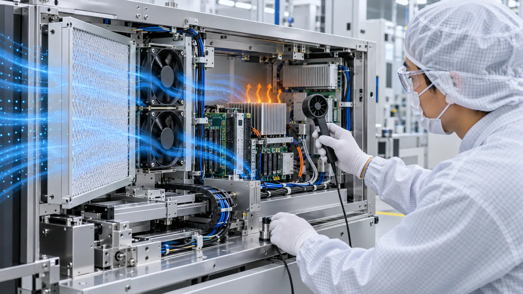
The first panel shows the intended path: air crosses the filter, passes through the fan and reaches the heatsink. The second shows what can happen when a gasket or frame does not seal. Total cabinet airflow may appear reasonable, but a portion of the air misses the restriction or the heat source. A local hotspot can remain while the fan appears healthy.
The third panel separates the checks. Measure useful airflow at the tool's critical path, vibration at the fan and sensitive structure, and noise at the agreed measurement location. The figure is qualitative, not CFD and not a product curve. It is a reminder to record the fan voltage, control state, filter state, temperature and mounting condition with each result.

Validation Sequence: From Bench Sample to Tool Release
The sample was accepted only after thermal, acoustic, vibration and interface checks were repeated in the actual equipment configuration.
Step one was documentation. The developer supplied the fan envelope, filter media and frame, heatsink drawing, duct section, guard, cable route, mounting torque, sensitive-axis vibration limit, noise target, voltage tolerance, control waveform and service interval. The original fan's part number and measured behavior were recorded so that a replacement could be compared against a known baseline.
Step two was an installed pressure-flow check. The team measured flow at the critical section and pressure across the complete path with the clean and service-limit filter. It repeated the measurement at several control settings. The report included instrument location, calibration status, air-density basis and whether the number represented total or useful local flow.
Step three was thermal soak. The tool ran its representative motion and processing sequence until temperatures stabilized. Inlet, outlet, heatsink base, board area and sensitive components were logged. A short startup pass was not accepted as a thermal result because enclosure heat soak can take much longer than fan startup.
Step four was vibration and acoustic review. The same fan command, mounting and filter state were used for the original and candidate. The team checked rotational tones, cable and guard contact, panel resonance, motion-stage response and noise at the operator location. The final sample was not chosen from a sound-pressure number alone.
Step five was fault and maintenance response. The test covered fan stop, missing FG, RD state, blocked filter, loose seal, low voltage and restart. The equipment owner defined the alarm, derating and service action. The fan-side supplier supplied the interface information and sample response, not the complete tool safety case.
Validation Result: A Traceable Fan Replacement Basis
The outcome was a controlled replacement basis that connected catalogue data to the installed tool without confusing the two.
The final comparison sheet listed the original fan and candidate samples by frame, thickness, voltage, connector, control, feedback and mounting. It also listed installed airflow at the measured pressure, fan current, acoustic spectrum, vibration at defined points, heatsink temperature, inlet temperature and response to the service-limit filter. The candidate was considered acceptable only when the complete set met the tool's defined limits.
The team retained a clear evidence boundary. Catalogue airflow and pressure were cited with their model and condition. Screening calculations were labelled illustrative. Project results included ambient, tool state, input power, control setting, filter condition and instrument location. This prevents a number from a clean bench from becoming an unqualified production promise.
Maintenance received a practical trigger. Filter differential pressure and useful airflow could be trended, while fan feedback and temperature provided a second line of warning. If vibration increased while FG remained in range, the tool could request inspection before a stopped-fan alarm occurred. The exact thresholds remained the responsibility of the equipment maker.
How MEGA Tech Supports Precision-Equipment Fan Customization
MEGA Tech develops and manufactures custom cooling fans, supporting fan selection, air-path review, sample validation and volume production around the customer's equipment.
We can review compact DC axial fans and centrifugal blowers by installed operating condition rather than catalogue headline. The review may include frame and thickness, airflow and static pressure at that airflow, filter and grille losses, shroud and seal geometry, flow direction, voltage tolerance, PWM, FG or RD feedback, connector, cable exit, mounting, vibration target, noise target and environmental assumptions. A candidate is then converted into a sample comparison plan.
Please provide the tool or enclosure sample, heat load by mode, required airflow and static pressure at that airflow, ambient and altitude, fan size, voltage, quantity, control interface, connector, noise target, vibration limit, filter condition, life assumption and service interval. If the project is a replacement, send the original fan model, drawings, photos, controller waveform and measured thermal or vibration data. The more complete the installed boundary, the more useful the sample recommendation.
MEGA Tech's scope is the custom cooling fan and its air-path validation. The equipment integrator retains responsibility for semiconductor process performance, motion accuracy, contamination qualification, cleanroom classification, EMC, electrical safety, machine guarding and final certification. We do not supply complete process tools, cleanroom systems, filters as a certified contamination solution or motion-control systems.
Engineer FAQ
Use these answers when a precision-equipment fan replacement is entering design review.
Q: Is a cleanroom fan selected by the clean-filter airflow? A: No. Release against the agreed service-limit filter and installed pressure, then retain clean-filter data for commissioning and maintenance trending.
Q: Can a higher-RPM fan solve a local hotspot? A: Not automatically. Check bypass, heatsink distribution, recirculation and local pressure before raising speed. Higher RPM can also increase tonal noise and vibration.
Q: Does FG prove that useful airflow is present? A: No. FG proves a speed-related signal is present. It does not prove that air reaches the critical heatsink or that the filter is sealed.
Q: Should soft mounts always be used? A: No. Compare vibration isolation, seal integrity, alignment and service life in the complete assembly.
Q: What should be measured for a sample? A: Measure airflow at the critical path, pressure, fan voltage and current, PWM, FG or RD, inlet and hotspot temperature, acoustic spectrum, vibration and filter state.
Q: Can MEGA Tech recommend a sample? A: Yes. Send the fan envelope, target airflow and pressure, voltage, quantity, control, noise, vibration, environment, drawings and current measurements.
Questions for a Design Review
These questions keep a fan selection connected to the precision tool rather than to a catalogue number alone.
Which component is the thermal limiting point? What is its temperature limit during the longest process cycle, and where is that temperature measured? Does the airflow actually cross the heatsink or board area, or can it bypass through a seal or cable opening? What are the clean and service-limit filter pressure drops? Which pressure definition is used in the supplier curve and installed test?
What vibration level is acceptable at the fan frame, panel and sensitive stage? Which tones are objectionable? What mounting torque, gasket compression and cable route are required? Does the candidate remain stable at the minimum PWM duty and during brownout recovery? How does the tool respond to fan stop, missing FG, RD alarm and blocked intake?
For a sample review, send the current fan model, tool drawings or physical sample, filter and heatsink data, target airflow and static pressure, fan size, voltage, quantity, control interface, connector, noise and vibration targets, ambient, altitude, life assumption and service condition. Use the MEGA Tech products catalogue, the fan selection tool and WhatsApp engineering contact. Request the P-Q curve or a custom specification at inquiry@cnmegatech.com.