
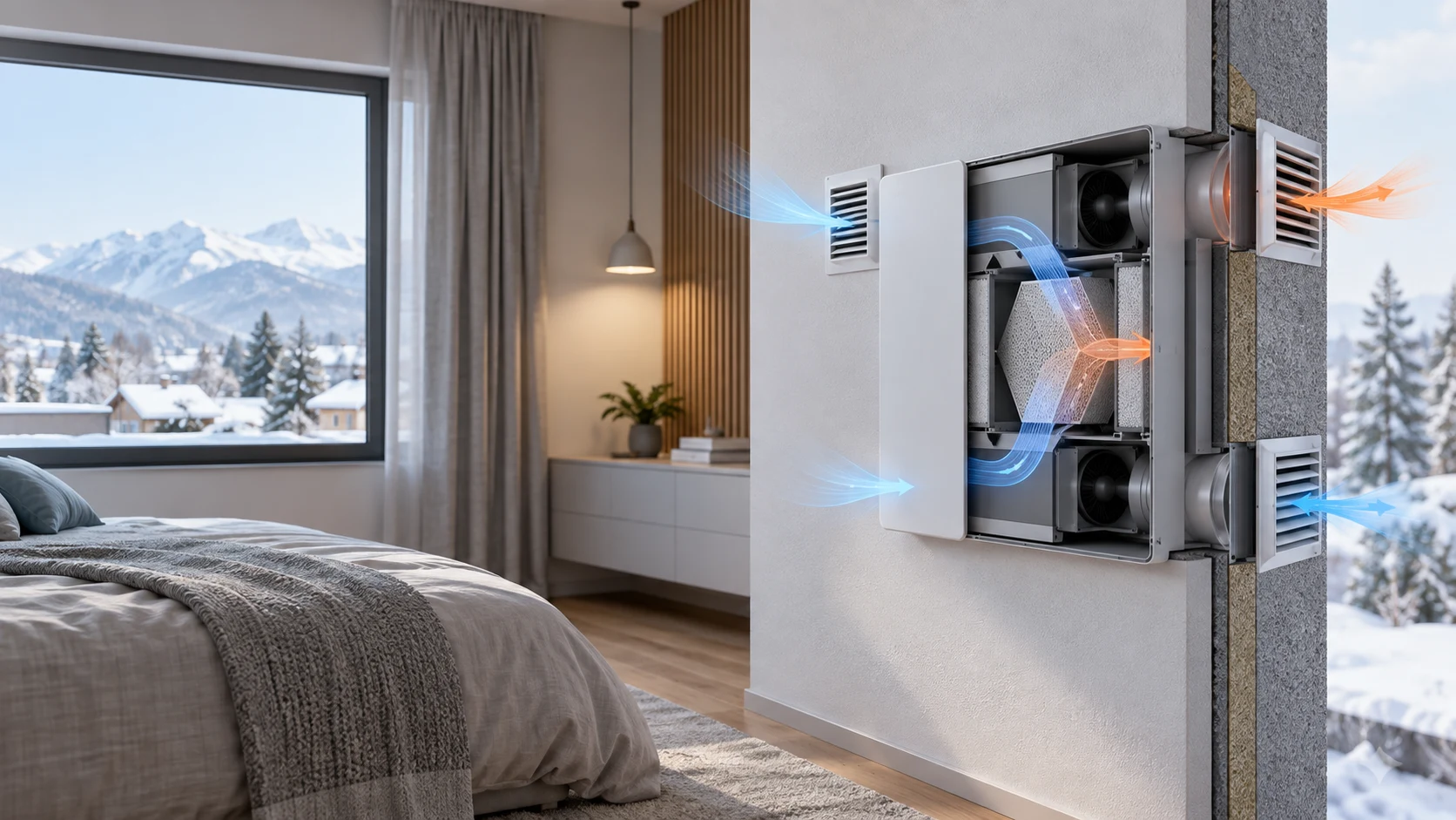
A Residential HRV Project With a Real Installed-Duty Problem
A Central European residential-ventilation manufacturer needed a quiet, compact centrifugal-blower candidate for a heat-recovery ventilation unit used in bedrooms.
The customer already sells a residential heat-recovery ventilation system and reported current sales of about 10,000 units per year, with an expectation of reaching about 20,000 units per year within two years. The next fan decision therefore had to work at two levels: it had to satisfy the installed airflow and acoustic brief, and it had to be repeatable as the product moved from sample evaluation to larger production.
The requested envelope was approximately 136 x 136 x 38 mm, with a typical electrical basis around 10–12 V and continuous 24/7 operation. The four requested airflow settings were 15, 20, 40 and 50 m³/h. At the highest setting, the customer wanted a measured system noise result below 30 dBA because the unit is installed in bedrooms.
This case describes a proposed engineering and sample-validation route for a custom 14038 centrifugal-blower candidate. It does not claim that the target has already been achieved, that a sample has passed, or that a public catalogue MG14038 axial-fan record is the same product. The operating point, noise, condensation and life results must be confirmed on the customer's actual HRV assembly.
Why an HRV Fan Cannot Be Selected From Free-Air Airflow
The ceramic heat exchanger, filters, grilles and internal transitions turn a nominal airflow request into a pressure-dependent selection problem.
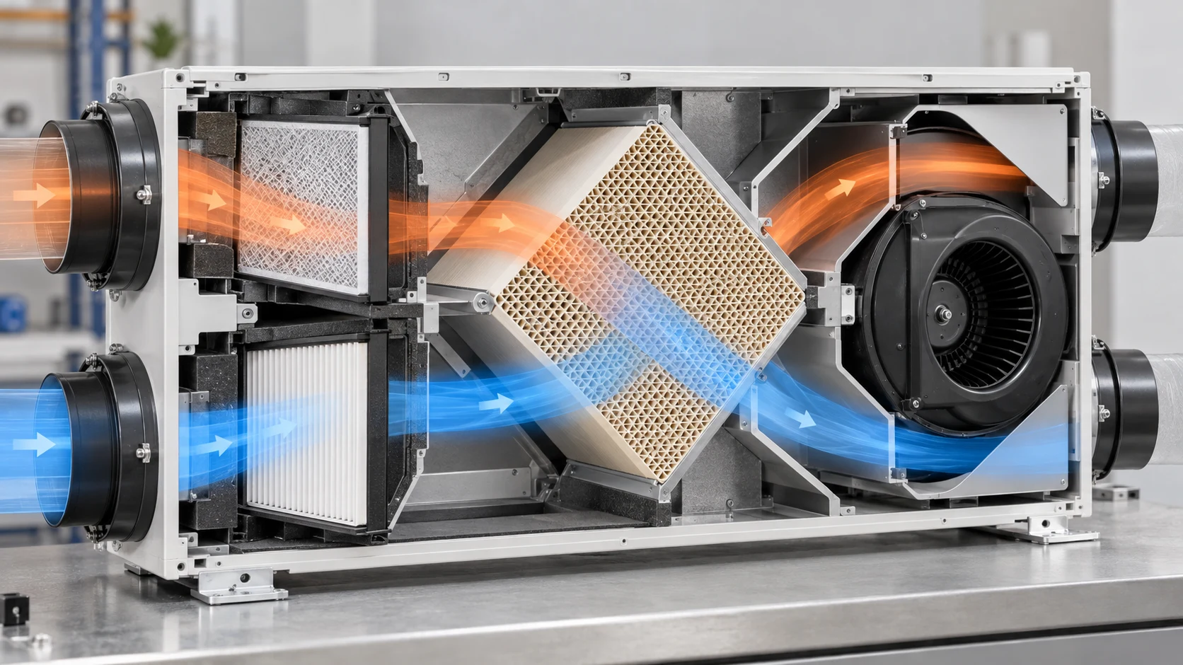
A heat-recovery ventilation unit does not deliver its catalogue airflow at zero resistance. The fan must move air through the supply or exhaust grille, the G3 and F7 filtration stages, the ceramic heat-exchanger core, seals, bends and any protective mesh. Each element consumes pressure, and the total changes as the filter loads or the installation is adjusted.
The engineering question is therefore not “can the fan move 50 m³/h in free air?” It is “what airflow does the candidate deliver at the pressure created by this exact HRV path, at the specified voltage and at the intended operating temperature?” The answer must come from a fan P-Q curve and a measured system-resistance curve that intersect at the installed operating point.
The team should measure both air paths separately. A supply path can have a different grille, filter condition and heat-exchanger direction from an exhaust path. If one motor is expected to reverse direction, the reverse-rotation duty must be tested rather than assumed: a centrifugal impeller may have different pressure, efficiency, noise, startup and bearing behavior in the reverse direction.
The Four Operating Points Must Be Defined Before Sampling
Four speed commands are useful only when each command has a defined airflow, pressure, voltage, noise and control state.
The supplied brief gives four airflow targets: 15, 20, 40 and 50 m³/h. Before a sample is approved, the HRV maker should record the static pressure at each target in both supply and exhaust paths. If the same pressure is not available, the four points should be documented as four separate operating conditions rather than treated as a single speed table.
At 50 m³/h, the customer specified a noise target below 30 dBA. That target needs a defined measurement method: microphone distance, room background, HRV enclosure, grille, filter state, mounting surface, airflow direction and whether the result is A-weighted sound pressure or sound power. A fan measured below 30 dBA in an open fixture can be louder after the grille and wall are installed.
The controller review should also define the command interface. A 10–12 V supply range, four speed levels, a PWM input, a voltage command or a local controller are not interchangeable. Record startup voltage, minimum stable command, current at each point, RPM or FG feedback, fault indication and the response after a power interruption.
| Operating point | Required airflow | Pressure to measure | Evidence to record |
|---|---|---|---|
| Low | 15 m³/h | Supply and exhaust static pressure | Voltage, current, RPM, noise and airflow |
| Low-mid | 20 m³/h | Pressure with clean filters | Command repeatability and restart behavior |
| High-mid | 40 m³/h | Pressure with heat exchanger installed | Noise, power and component temperature |
| Maximum | 50 m³/h | Pressure at the complete installed path | Noise target, airflow stability and margin |
Low-Noise Design Starts With the Air Path, Not Only the Motor
The bedroom requirement makes tonal noise, turbulence, structure-borne vibration and grille interaction part of the fan selection.
The 30 dBA target at 50 m³/h should be treated as a system-level acceptance target. The blower can be quiet on a bench and still create a tonal peak when its blade-passing frequency interacts with a grille, filter pleat, ceramic channel or short outlet. The wall, mounting bracket and plastic enclosure can also amplify vibration even when the fan's own casing measurement looks acceptable.
A practical sample plan compares at least two mounting conditions: the production-like HRV enclosure and a controlled reference fixture. Record the background noise first, then measure at each of the four airflow settings with the final grille and heat-exchanger arrangement. If the result fails only after enclosure installation, inspect clearance, outlet contraction, flexible isolation, fastener preload and the distance between the impeller and the first restriction.
Noise should be reviewed together with useful airflow. Reducing speed can lower sound but may also move the fan below the required pressure point. Conversely, increasing speed to recover filter loss can increase tonal noise and power. The design review should therefore include a noise-versus-airflow map, not a single best-case dBA number.
The Ceramic Core and Filter Stack Set the Pressure Margin
G3 and F7 filters can have different clean and loaded pressure losses, while a ceramic heat exchanger adds a flow-dependent restriction that must be tested in the final orientation.
The customer named G3 and F7 filtration stages and a ceramic heat exchanger. These labels identify the intended filtration and recovery architecture, but they do not provide a complete pressure curve. The HRV maker should obtain the actual filter pressure-drop data at 15, 20, 40 and 50 m³/h, then measure the core and grille losses in the same flow direction and mounting arrangement.
A useful test records differential pressure before and after each major element. This separates a fan shortfall from a filter issue and shows which component consumes the available margin. The loaded-filter test should use a defined service condition or a controlled resistance method; it should not rely on an unrecorded dust exposure that cannot be repeated.
The candidate 14038 blower should be compared on the combined curve. If the system operates close to the fan's zero-flow or unstable region at 50 m³/h, small changes in filter loading or installation can cause a large airflow change. A stable operating region with measurable margin is more useful than a high free-air number.
Winter Operation: Temperature, Humidity and Condensation
A residential HRV unit can see cold outdoor air, warm humid indoor air and repeated dew-point crossings in the same day.
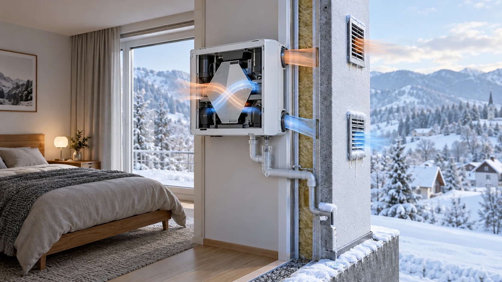
The stated outdoor design range is −20 °C to +40 °C, with possible high humidity and condensation inside the ventilation system. The sample test should reproduce the thermal sequence rather than expose the fan to a single steady temperature. Record inlet temperature, indoor humidity, local surface temperature, dew point, fan voltage, current, speed and restart behavior during cold start and recovery.
Condensation is an assembly problem as well as a fan problem. Water management, drain paths, insulation, seals, the ceramic core and the fan inlet geometry determine whether droplets reach the motor or electronics. The fan supplier can define the candidate's intended temperature and humidity limits, but the HRV manufacturer remains responsible for the complete condensation strategy and for preventing pooled water from reaching sensitive parts.
Cold-start testing should include a soak at the lowest required temperature, startup at the specified minimum voltage, transition to each speed command and a controlled warm-up. The team should inspect for rubbing, delayed startup, unstable speed, abnormal sound, ice or water movement. Any pass/fail limit must be written before the test so that the result is not interpreted after the fact.
A Simple Validation Bench Makes the Sample Decision Repeatable
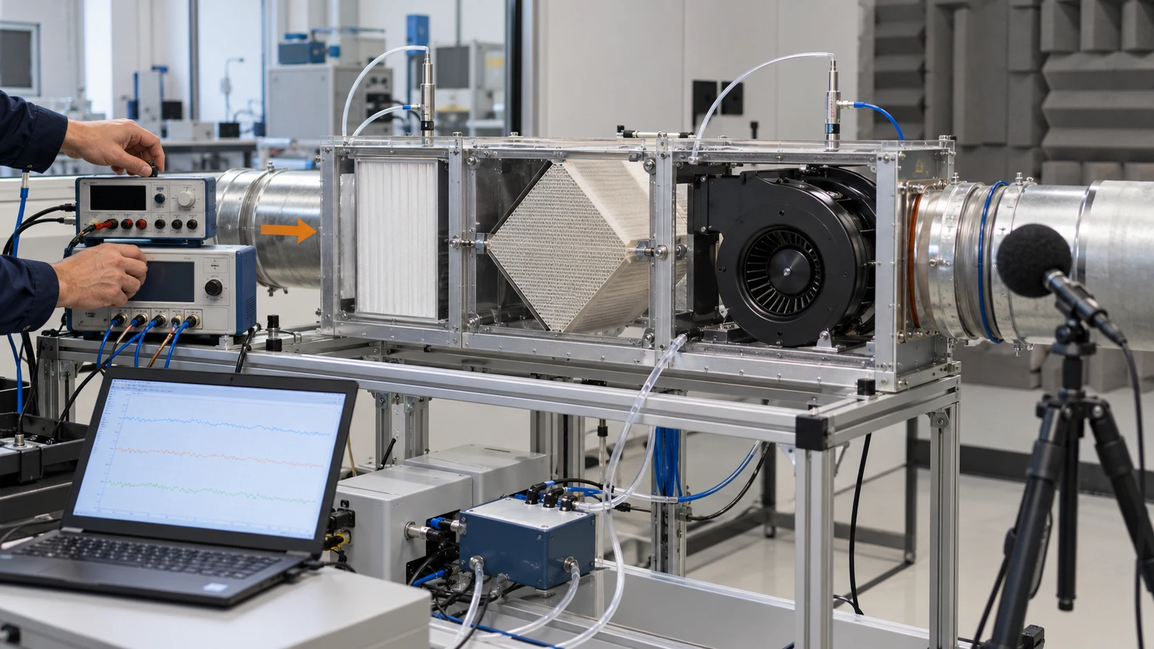
The proposed test bench combines the actual fan, filters, ceramic core, grilles, pressure taps, airflow measurement and acoustic instrumentation.
The most useful bench is not necessarily the largest one. It is the one that reproduces the restrictive elements and allows each measurement to be repeated. The HRV maker can build a representative duct fixture with the 136 x 136 x 38 mm envelope, production mounting, filter frames, ceramic core, supply and exhaust grilles, pressure taps and a controlled outlet resistance.
At each operating point, record airflow, static pressure, voltage, current, command, RPM or FG, noise and the temperature at the fan inlet and the limiting equipment location. Repeat the run after the unit reaches thermal steady state. If the fan is expected to serve both supply and exhaust, repeat the complete matrix for each direction and keep the two datasets separate.
The bench should also include a blocked or loaded-filter condition and a power-interruption test. These are not attempts to create a product claim; they reveal whether the chosen control and alarm strategy can protect the bedroom unit when resistance changes or the motor stops.
Animated Engineering Map: From Command to Delivered Air
The particle figure shows the measurement chain that connects a speed command to useful airflow through the complete HRV path.
The animation is qualitative. Blue particles represent air moving through the selected path, grey blocks represent pressure-producing components and the orange region represents the heat-exchanger section. It is not a CFD result, not a P-Q curve and not product performance data. Its purpose is to help the design team agree where to measure before the sample is approved.
The most important comparison is the difference between the requested airflow and the airflow actually delivered after the filter and ceramic core are installed. If the system pressure rises, the operating point moves along the candidate curve. The control response must recover only as far as the noise, power, temperature and life limits allow.
For the four-speed product, the controller should store or reproduce four repeatable states. The measurement sheet should identify the selected voltage, command and path direction so that a later production audit can distinguish a wiring change from a mechanical pressure change.

What a Production-Ready Sample Package Should Contain
The sample decision should leave the customer with evidence that purchasing, controls and service teams can use later.
The technical package should include a candidate datasheet, dimensional drawing, P-Q curves at the agreed voltage conditions, electrical data at the four operating points, noise results with the measurement method, operating temperature and humidity assumptions, connector and control definitions, and the fan mounting and cable-routing details. Any IP or certification statement must be tied to the actual model and documentation; it should not be inferred from the enclosure or from a different product family.
The production review should also record the sample revision, impeller and housing configuration, bearing option, firmware or control assumptions, filter condition, heat-exchanger revision and test equipment. If any requested value is not yet measured, label it as open rather than filling the gap with a catalogue maximum or a supplier estimate.
The customer's annual volume information is useful for planning a long-term cooperation path, but it is not a reason to skip engineering acceptance. First prove the installed duty and repeatability. Then align the released specification, sample approval, change-control process, packaging and supply plan with the expected 10,000-unit current scale and approximately 20,000-unit two-year ambition.
| Evidence | Required comparison | Open question before release |
|---|---|---|
| Airflow and pressure | All four points in both intended paths | What pressure is present at each airflow? |
| Acoustics | Production-like enclosure and background noise | Where and how is the 30 dBA target measured? |
| Electrical | Voltage, command, current and feedback | Can the controller repeat four stable states? |
| Environment | Cold start, warm operation, humidity and condensation | Which limits belong to the fan and which to the HRV assembly? |
| Mechanical | Mounting, clearance, cable route and grille | Does the sample match the released enclosure? |
| Documentation | Revision-controlled drawings and curves | Are unmeasured values clearly marked open? |
How MEGA Tech Can Support the 14038 HRV Development
MEGA Tech can review the installed duty and develop a sample around the customer's pressure, airflow, voltage, noise and environmental constraints.
For this project, the right starting point is the customer’s HRV assembly and its measured air path, not a part number alone. MEGA Tech can review a compact centrifugal-blower candidate around the approximate 136 x 136 x 38 mm envelope, the 10–12 V electrical basis, the four requested airflow states and the 24/7 operating assumption. The sample discussion can include the mounting interface, connector, cable route, command and feedback signals, noise measurement point and the direction-of-flow requirement.
Please provide the current unit or representative air-path fixture, the G3 and F7 filter data, the ceramic-core pressure loss, the supply and exhaust grille geometry, the required pressure at 15/20/40/50 m³/h, voltage tolerance, control interface, noise method, temperature and humidity sequence, condensation boundary, service-life assumption and sample quantity. If the same blower must reverse, state that explicitly and test both directions.
MEGA Tech’s scope is custom fan selection, sample development and comparative validation around the supplied operating point. The HRV maker remains responsible for the heat-recovery core, filters, controller, drainage, condensation management, electrical safety, EMC, final acoustic qualification and the complete residential product approval.
Engineer FAQ
These questions should be answered before selecting a fan for a residential heat-recovery ventilation unit.
Q: Can a 14038 blower be approved from the frame size alone? A: No. The airflow, static pressure, voltage, control, noise, environment and mounting must be verified on the installed HRV path.
Q: Is 50 m³/h the same as 50 m³/h at the fan outlet? A: Not necessarily. The relevant value is delivered airflow through the filters, ceramic core, grilles and other restrictions at the specified pressure.
Q: Can one centrifugal blower simply reverse for supply and exhaust? A: Do not assume that. Reverse operation requires separate airflow, pressure, efficiency, noise, startup and life validation.
Q: Does a low open-bench dBA result prove bedroom suitability? A: No. Measure the production-like HRV enclosure, wall or mounting structure, grilles, filters and the complete air path.
Q: What does condensation testing need to include? A: Temperature, humidity, dew point, cold soak, startup, warm-up, water management and inspection of the fan, core and enclosure together.
Q: Can MEGA Tech provide a final specification before seeing the pressure target? A: A meaningful specification needs airflow and static pressure at that airflow, plus voltage, controls, envelope, noise and environment. A sample can then be validated in the customer’s unit.
Questions for a Design Review
Use these questions to convert the customer brief into a repeatable sample-approval decision.
- What static pressure exists at 15, 20, 40 and 50 m³/h after the G3 filter, F7 filter, ceramic core, grille and internal air path are installed?
- Is the 30 dBA target measured as sound pressure or sound power, at what distance, with what background and in which enclosure condition?
- Does the design use one blower in two flow directions or two separately oriented flow paths, and what evidence supports that decision?
- What are the minimum and maximum supply voltages, the four control commands, the startup behavior and the required FG/RD or alarm interface?
- What temperature, humidity, dew-point and cold-start sequence represents the Slovenian installation, and where can condensate drain safely?
- Which values are measured sample results, which are design targets and which remain open pending the customer’s HRV fixture?
- What information must be submitted to MEGA Tech for a sample recommendation: fan envelope, airflow, static pressure, voltage, quantity, control, noise method and environment?