The Inverter Passed the Component Test and Failed the Installed Air Path
An anonymised EV power-electronics team needed a custom cooling fan for an inverter, onboard charger and DC-DC converter assembly with limited pressure margin.
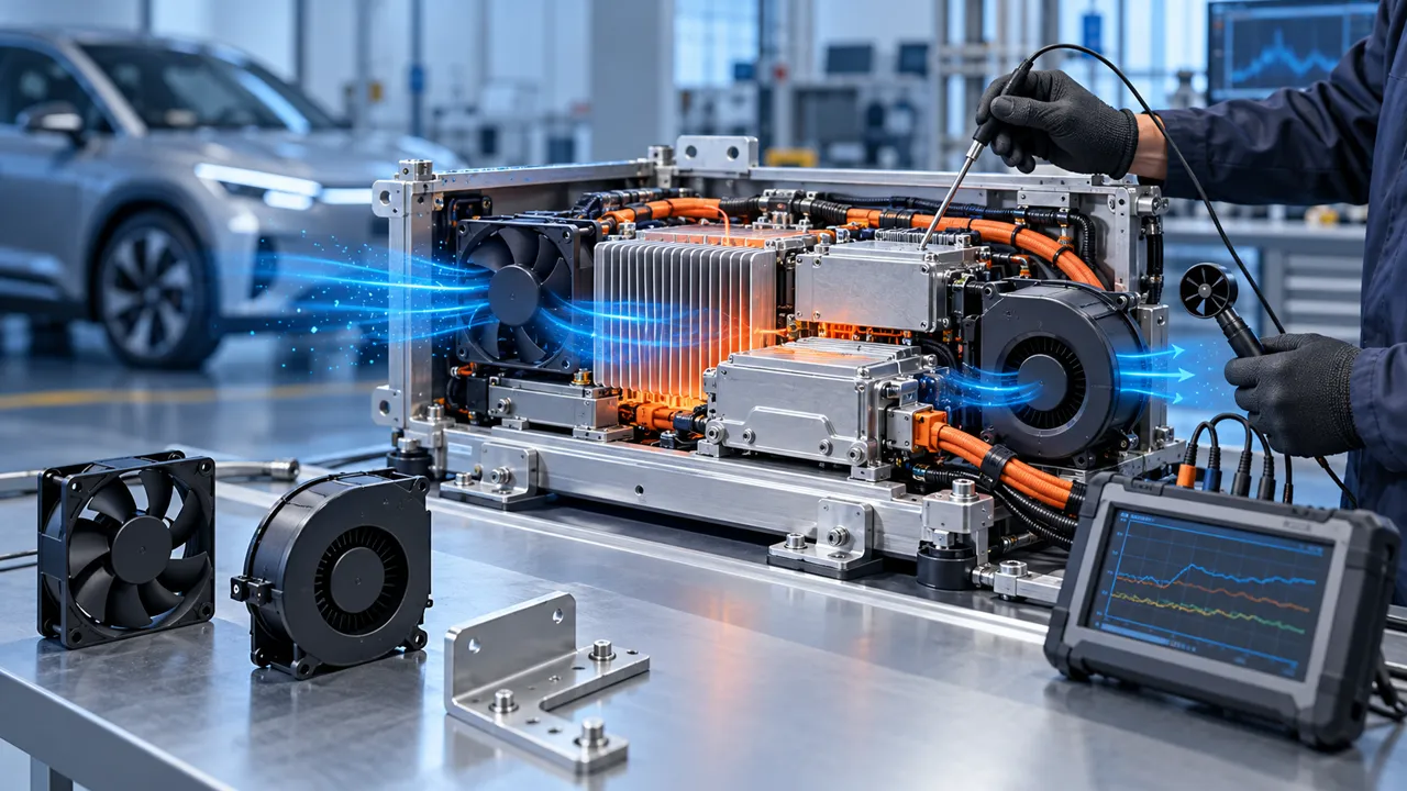
The bench test used an open heat sink and a clean air path. The installed module used a cover, cable harness, grille, duct bend and a compact heat exchanger. During a high-load sequence the inverter hotspot rose faster than expected even though the fan was at the commanded speed. The onboard charger remained within its local limit, but the shared outlet restriction reduced useful flow across the inverter heat sink.
The first proposal was to increase fan speed. That would have raised noise, current and bearing stress without proving that the extra air reached the heat source. The engineering question became: what airflow and static pressure are required at the real operating point, under the target inlet temperature and mounting condition?
The vehicle, customer and measured acceptance values remain confidential. This case describes the fan-side engineering workflow and its boundary. It is not a vehicle certification claim, an automotive safety approval or a universal performance guarantee.
Separate Inverter, OBC and DC-DC Heat Loads
A shared cooling path can hide which module actually consumes the thermal margin.
Power electronics do not create one identical heat profile. An inverter can generate a short high-load hotspot, an onboard charger can run for a longer charging interval, and a DC-DC converter can remain active during a different vehicle state. If all three are averaged into one cabinet temperature, the limiting component can be missed.
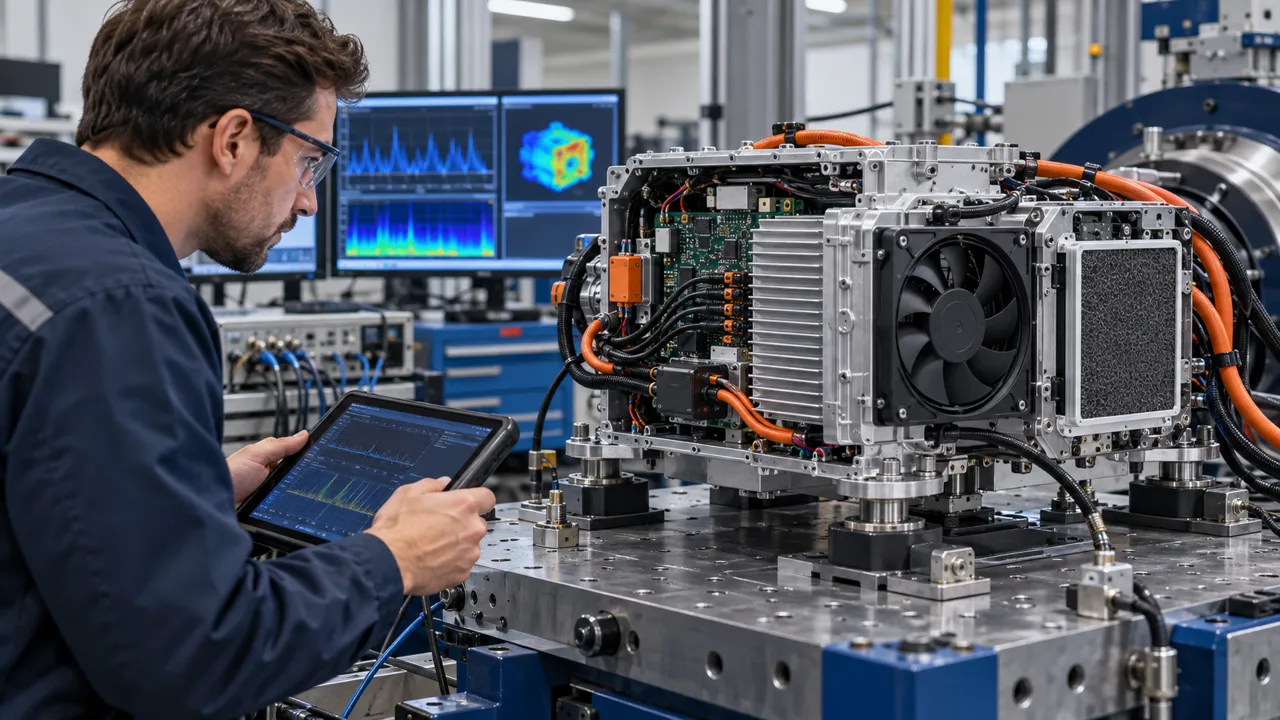
The review placed sensors at the inlet, heat-sink base, outlet and local electronics surfaces. Current, voltage, fan command, RPM and airflow or pressure were logged with the thermal channels. This made it possible to tell whether a temperature rise followed electrical load, rising inlet temperature, an air-path restriction or a fan control transition.
The design target was not simply a lower average temperature. It was a defined margin at each required operating state, with the actual air density, restriction and mounting basis written beside the result.
| Measurement | Why it matters | Evidence |
|---|---|---|
| Module heat load | Each converter has a different limiting state | Time-aligned thermal and electrical trace |
| Inlet temperature | Sets available cooling margin | Sensor location and ambient basis |
| Installed pressure | Moves the fan operating point | Pressure taps around the air path |
| Heat-sink temperature | Shows local thermal bottleneck | Sensor and acceptance location |
| Fan control | Changes flow, noise and current | Command, RPM, FG/RD and response |
Select the Fan at Installed Pressure
The candidate was compared on the system curve created by the cover, grille, duct and heat exchanger.
A free-air CFM value is not an installed operating point. The EV module introduced losses at the inlet grille, a bend, the heat sink and the outlet. The team measured or estimated the resistance across the actual path, then compared it with candidate fan P-Q behavior. A small axial fan may suit a short open path; a centrifugal blower may be more useful where the air must turn through a narrow channel.
The sample review considered frame and thickness, voltage tolerance, current, PWM response, FG or RD feedback, connector, cable exit, noise target, temperature range and quantity. The largest nominal airflow option was not automatically the best option because its pressure, packaging or current could be wrong for the module.
The candidate was accepted for the next test only after the fan, duct and heat sink were mounted as they would be in the customer assembly. The result remained provisional until the full load and temperature states were repeated.

Check Hot Inlet Air and Under-Hood Density Basis
Vehicle installation conditions can move the thermal result even when the fan command is unchanged.
The team defined the inlet-temperature basis for charging, traction and parked hot-soak states. The fan was not evaluated only at a comfortable room temperature. Hot inlet air reduces the temperature difference available for heat rejection, while air-density changes influence mass flow and fan pressure behavior. The test record stated the temperature, pressure and altitude assumptions used for each comparison.
The module was checked for recirculation. Hot discharge air could return to the inlet through a gap around the cover or harness, making the fan appear underpowered. The test therefore included the intended seals, service panels, grille and neighboring components. A change in vehicle packaging could require another sample even if the fan frame stayed unchanged.
The thermal map separated a fan-side issue from a heat-sink or interface issue. More airflow cannot repair poor thermal contact, and a larger fan cannot compensate for a discharge path that returns hot air to the inlet.
Tune PWM Without Creating a New Thermal or Acoustic Limit
Variable speed was useful only when the command, pressure margin and thermal response were validated together.
The controller schedule was tested across idle, charging, traction and peak converter states. The team recorded the actual RPM rather than treating a PWM percentage as a universal speed. A command that works on one supply can fail at a lower harness voltage or with a different connector and control reference.
The low-speed region was checked for startup and stable rotation. The high-speed region was checked for noise, current, vibration and thermal benefit. If a higher command increased noise without moving useful airflow through the heat sink, the air path or fan choice needed review instead of another speed increase.
FG or RD feedback was used to confirm the fan-side state. The vehicle controller still had to decide whether a missing signal produced a warning, a power limit, a charger stop or another system action. The fan signal did not replace vehicle-level protection logic.
Validate Vibration, Mounting and Harness Clearance
Automotive power-electronics fans see mechanical constraints that are absent from an open bench.
The bracket, fastener preload and elastomer interface were reviewed with the fan installed. The team checked that the mount did not distort the frame or close the inlet. It also examined whether the harness could bridge an isolation feature, touch the guard or transmit vibration into a cover.
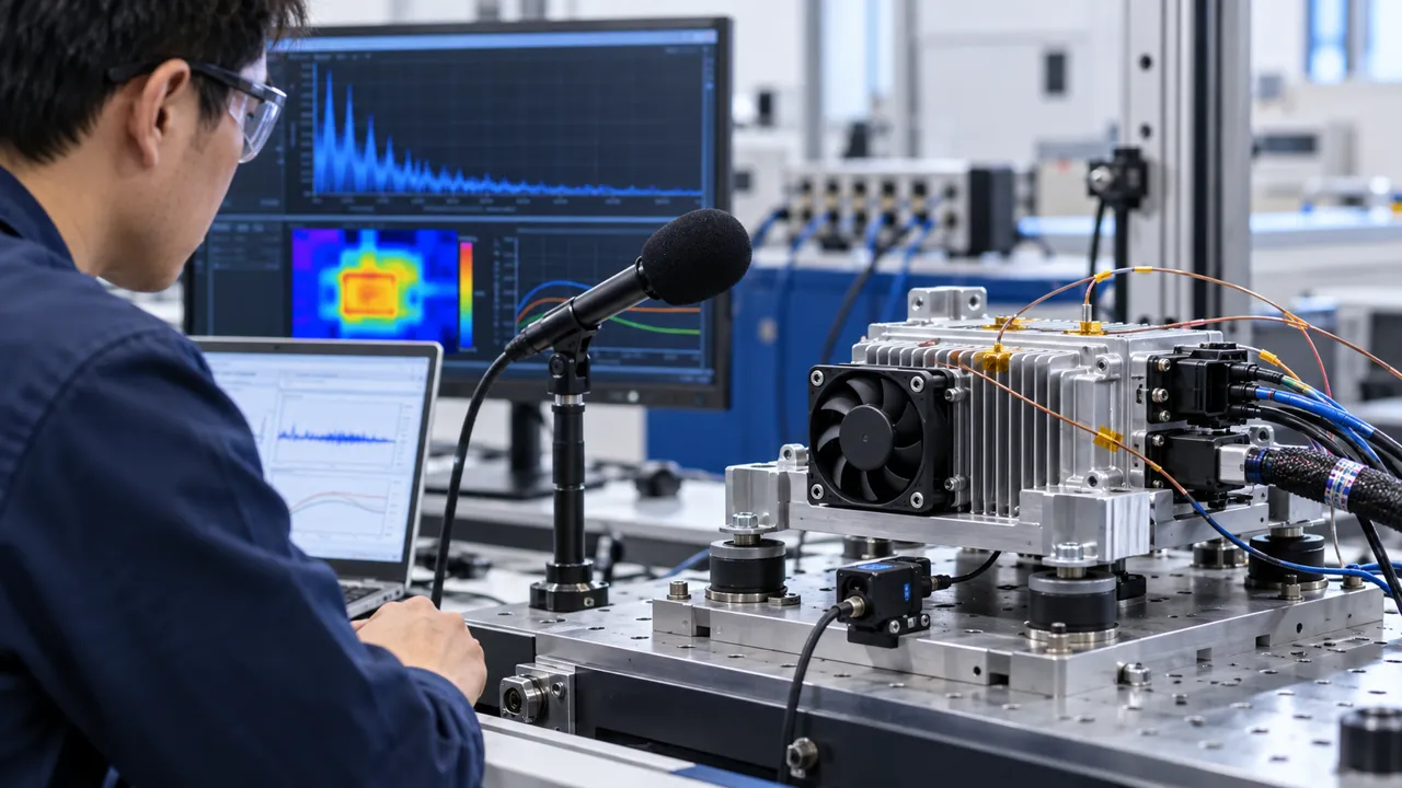
Vibration testing used the customer-defined fixture and mounting condition. The fan was monitored for speed feedback, current, noise, movement and contact. A quiet result at one speed was not accepted as proof across the full control range because structural response can change with RPM and temperature.
MEGA Tech can help adjust the fan-side mounting, connector and cable exit around the customer design. The customer owns the vehicle vibration profile, complete bracket design and qualification plan.
| Detail | Failure if missed | Review evidence |
|---|---|---|
| Fan mount | Force or frame distortion changes flow | Installed mechanical check |
| Harness route | Cable bridge or contact creates a fault | Clearance and retention evidence |
| Inlet grille | Restriction lowers installed airflow | Pressure and flow at the grille |
| Outlet seal | Hot recirculation reduces margin | Smoke or flow-path check |
| Control reference | PWM or FG/RD behavior changes | Interface and low-voltage test |
Repeat Cold Start, Power Interruption and Hot-Soak States
A fan sample is not ready for production when it only works in steady room-temperature operation.
The electrical test included the lowest specified supply, cold start, repeated start, brief interruption and hot restart. Current and feedback timing were recorded because a controller can interpret a slow or missing tach signal as a fault. A fan that starts on a bench supply may not start after harness drop, protection cycling or a hot-soak event.
The thermal sequence repeated the actual transition that made the module hot. The team recorded how quickly the fan reached a valid speed, how quickly the heat sink responded and whether the controller command overshot the useful operating point. The acceptance rule was tied to the module and vehicle requirement, not to a generic motor start time.
If a fan fault occurs, the vehicle system must define the next action. MEGA Tech can supply the fan sample and interface evidence; it does not own traction control, charging safety, battery protection or vehicle-level emergency behavior.
Result: A Fan Candidate Matched to the Power-Electronics Duty
The project closed when the team could explain the thermal margin, pressure point, electrical interface and mechanical installation together.
The release record captured the module heat states, inlet basis, fan envelope, voltage and current, PWM and FG/RD behavior, installed pressure, airflow measurement point, heat-sink temperatures, bracket, harness, noise and vibration conditions. This made later changes traceable: a new grille, heat exchanger, cover, cable route or controller command would be treated as a new validation input.
The transferable result was a method rather than an automotive certification statement. The customer could see when the inverter was pressure-limited, when the OBC was load-limited, when a higher command added noise without useful flow, and when a fan feedback change required a system response.
A different vehicle platform or converter package can require a different fan, duct and sample. Matching the outline size alone does not prove equivalent thermal or electrical performance.
How MEGA Tech Supports Custom Automotive Cooling Fans
We help automotive electronics teams move from a power-electronics duty to a fan sample that can be tested in the real module.
MEGA Tech develops and manufactures custom cooling fans, including DC axial fans and centrifugal blower options for restrictive air paths. Our work can cover fan selection, air-path review, sample validation and volume production. We select from airflow and static pressure at the operating point, not a part number or free-air CFM alone.
For a first review, send inverter/OBC/DC-DC heat load by state, inlet temperature and pressure basis, required airflow and static pressure, fan envelope and mass, voltage tolerance, PWM/FG/RD or alarm interface, connector and harness, mounting, noise and vibration target, environment, quantity and life assumption. We can then evaluate a sample on the customer assembly.
We do not supply complete vehicles, batteries, inverters, chargers, coils, liquid loops, controllers or automotive certification. Those remain with the vehicle and system integrators. Start with the fan selection tool, review the DC axial fan range, or request a sample on WhatsApp.
Engineer FAQ
These questions usually decide whether an automotive electronics fan sample needs another design iteration.
Q: Is free-air CFM enough for an inverter? A: No. The grille, heat sink, duct, cover and outlet create the installed pressure point.
Q: Can PWM percentage define the cooling result? A: No. Record actual RPM, installed airflow and pressure at the supplied voltage and temperature.
Q: Does a fan supplier provide automotive certification? A: The fan manufacturer can provide product and sample evidence, but vehicle qualification and system certification belong to the customer and integrators.
Q: Should the OBC and inverter share one fan? A: It depends on heat order, pressure loss, recirculation and control states. Measure each limiting module.
Q: What does MEGA Tech need for a first sample? A: Heat load, airflow and pressure, inlet temperature, voltage, control, envelope, noise, vibration, environment, quantity and the real module.
Questions for an Automotive Fan Design Review
Use this checklist with thermal, mechanical, electrical, controls and procurement teams before freezing the power-electronics fan.
- What heat load and inlet temperature define inverter, OBC and DC-DC peak states?
- What airflow and static pressure are required at the installed grille, heat sink and outlet?
- What voltage tolerance, PWM reference and FG/RD behavior exist at the fan connector?
- What low-voltage, cold-start, hot-restart and power-interruption states are required?
- Can the harness, bracket or cover create a bypass, contact risk or vibration path?
- Where is the actual thermal acceptance sensor and how is it correlated with the fan operating point?
- What noise and vibration measurement point represents the vehicle installation?
- What happens after missing feedback: warning, power limit, charger stop or service action?
- Which platform change triggers a new sample: duct, heat source, cover, controller, grille or mount?