
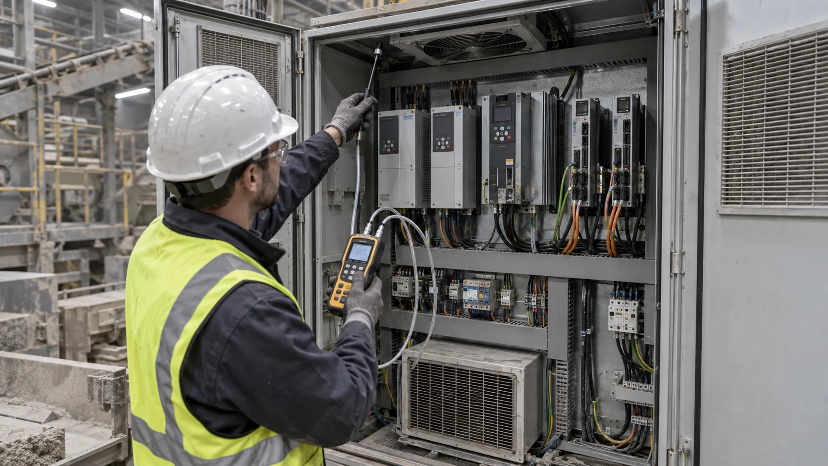
A VFD Cabinet Can Overheat While the Fan Is Running
A control cabinet may show a normal fan RPM and still develop a hot upper zone, a blocked drive heatsink path or a thermal derating alarm.
Variable-frequency drives and servo amplifiers convert electrical power into motion, but part of that power becomes heat inside the drive, braking components, filters and control electronics. In a tall enclosure, warm air can stratify above the drive line-up. In a dusty plant, a filter can add pressure while the fan continues to rotate. In a cabinet with unsealed cable entries, air can bypass the heatsink and leave the limiting component hot.
The engineering question is therefore not simply whether the cabinet has a fan. It is whether the installed fan, filter, clearances, baffles and drive heatsink path deliver the required cooling at the worst load and service condition. The fan's free-air number, command percentage or RPM is only one input to that answer.
This article gives controls, thermal and procurement teams a practical method for reviewing VFD cabinet airflow. The estimates are examples, not a drive manufacturer's derating curve. The cabinet owner remains responsible for electrical safety, drive installation, EMC, enclosure protection and machine risk; MEGA Tech supports the fan and air-side interface.
Map Drive Losses Instead of Guessing From Motor Power
The motor rating is not the cabinet heat load. Drive efficiency, switching state, braking and auxiliary devices determine what the fan must remove.
Start with the drive manufacturer's loss data at the actual current, carrier frequency, output frequency and overload duty. Add braking resistor or regenerative losses that enter the cabinet, line reactors, output filters, contactors, control power and other warm devices. A cabinet with several moderate drives can have a higher total heat load than one large drive if the losses are distributed poorly.
Create a state matrix for low speed, rated speed, acceleration, deceleration, overload, standby and simultaneous-drive operation. Record drive current, DC-bus behavior, heatsink temperature, cabinet inlet and upper-zone temperature. Include the production mounting clearances and the external equipment next to the cabinet, such as ovens, motors, compressors or sun-heated walls.
Thermal estimates should be replaced with measured losses during prototype testing. Use the estimate to size the test instrumentation and identify the likely limiting zone. A fan placed near the coolest air sensor can appear effective while the upper heatsink or braking section remains above the allowed temperature.
Also record the drive's own internal fan state if it has one. An enclosure fan and a heatsink fan can interact: one may raise the inlet temperature of the other, or a failed internal fan may be hidden by a cool cabinet-air reading. The validation record should name every fan, every sensor position and every airflow direction so a service technician can reproduce the diagnosis instead of relying on a door thermometer. Include the cabinet door, filter frame and cable glands exactly as they will be delivered; a temporary open panel can make a weak design look healthy.
A First Cabinet Airflow Estimate
A heat-balance calculation gives the first airflow target, but the filter and drive heatsink pressure determine which fan can actually deliver it.
Consider an illustrative cabinet with 900 W of internal loss during simultaneous VFD operation. If the permitted average cabinet air rise is 15 K, Q = P/(rho x cp x delta T). With an air heat-capacity estimate of 1,200 J/(m3 K), Q = 900/(1,200 x 15) = 0.05 m3/s, or approximately 106 CFM.
This is only an average-air screen. The drive heatsink may require local flow, and the upper zone may be hotter because of stratification. If the enclosure receives 150 W of external heat from a hot neighboring machine or sunlight, the screen becomes 1,050/(1,200 x 15) = 0.0583 m3/s, or approximately 124 CFM.
Now add pressure. A filter, inlet grille, heatsink channel, baffle, cable bundle and exhaust louvre may require 160 Pa at the target flow. The candidate must deliver about 106 to 124 CFM at 160 Pa and at the service-limit pressure. A fan rated at 120 CFM in free air is not evidence that the cabinet will meet the drive temperature limit.
| Input | Example | Use in the review |
|---|---|---|
| Drive and auxiliary loss | 900 W estimate | Defines the simultaneous-load state |
| External heat | 150 W estimate | Checks site installation condition |
| Allowed average rise | 15 K | Screens 106 to 124 CFM |
| Installed pressure | 160 Pa plus filter drift | Select the loaded P-Q point |
| Acceptance data | temperature + flow + pressure | Releases the installed assembly |
Animated Model: Lower Inlet, Upper Hot Zone and Loaded Filter
The air path can look open while warm air stays above the drive line-up or bypasses the heatsink altogether.
The animated schematic below shows three states. In the balanced state, blue particles enter low, cross the drive and leave through the upper exhaust. In the stratified state, amber heat collects in the upper region because the inlet, baffle or fan position does not sweep the limiting component. In the loaded-filter state, red restriction markers show the operating point moving toward lower airflow.
This is a qualitative model, not a CFD result or a universal cabinet design. Its value is in making the test sequence visible. Measure at lower, middle and upper points, compare the drive heatsink inlet and outlet, and repeat the test with the filter at its service limit. A single door-mounted thermometer cannot show the distribution.
If the fan command rises but the upper zone remains hot, check flow distribution and bypass before selecting a faster fan. A high-speed fan that short-circuits through cable openings can add noise and power without reaching the heatsink. A baffle, sealed cable path or different fan position may deliver more useful cooling than a larger free-air number.

Fan Placement: Positive Pressure, Exhaust and Internal Circulation
The best fan position depends on contamination, filter strategy, cabinet height and the drive's own heatsink path.
A filtered inlet fan can create positive pressure and reduce unfiltered leakage through cable entries, but only if the enclosure openings are controlled. An exhaust fan can remove warm air effectively, but uncontrolled gaps may draw dust through the cabinet. An internal circulation fan can break stratification while adding little net heat rejection if the cabinet has no defined inlet and outlet path.
For tall cabinets, test lower-to-upper flow and the reverse arrangement rather than relying on intuition. Some drive manufacturers specify clearances above and below the heatsink because the drive's own cooling path depends on those spaces. A roof exhaust that is too close to the upper drive outlet can add resistance or create a recirculation pocket.
Use smoke, particle visualization or a simple velocity survey only as a first diagnostic. The release decision still needs pressure, flow and component-temperature evidence. Document the fan direction, filter location, louvre free area, cable openings and door position so a service replacement does not silently reverse the intended air path.
| Arrangement | Potential benefit | Main risk to validate |
|---|---|---|
| Filtered inlet + upper exhaust | positive pressure and natural hot-air path | bypass and exhaust clearance |
| Upper exhaust fan | removes warm cabinet air | unfiltered leakage and low inlet flow |
| Internal circulation fan | reduces stratification | little net heat rejection |
| Drive heatsink fan module | targets the local loss | maintenance and reverse-flow resistance |
| Closed-loop cooler | separates harsh dust environment | condensation, heat-exchanger and service boundary |
Filter Pressure and Drive Derating
A dirty filter can move the fan operating point before the VFD reports a clear alarm.
Test the clean filter, the intended service-limit filter and a deliberately restricted diagnostic state. Record differential pressure, fan command, actual RPM, current, flow if available and the hottest drive surface. The service alarm should arrive before the fan reaches maximum command or the drive temperature exceeds its allowable condition.
An illustrative path may require 160 Pa clean and 230 Pa at service limit. If the candidate fan has little pressure headroom above 230 Pa, the controller can no longer recover airflow by increasing speed. The drive may still see a normal fan RPM, but the heatsink flow and thermal margin have fallen. The answer may be a higher-static-pressure fan, a larger filter, a lower-resistance louvre or a shorter service interval.
Do not use a generic filter multiplier. Filter media, face area, dust type, humidity and rated flow determine the pressure curve. Keep the actual filter part number and service condition in the fan-selection record so future replacement work uses the same boundary.
High Ambient, Altitude and Condensation
The cabinet fan must operate inside the real site environment, not only in a 25°C room with clean air.
At high ambient, the same heat loss creates a higher component temperature because the inlet air starts closer to the drive limit. At altitude, lower air density changes mass flow, heat capacity and fan pressure behavior. Use the site altitude and temperature basis when interpreting the fan curve and the drive manufacturer's derating instructions.
A screened example: if a limiting drive surface is allowed 70°C and the cabinet inlet rises from 30°C to 40°C, the available temperature rise falls from 40 K to 30 K before component and distribution margins are considered. If the cabinet air-conditioning or a cold surface drops below the local dew point, condensation becomes a separate risk. Correct air guidance and controlled transitions matter as much as maximum fan speed.
Repeat the cabinet test at high ambient, expected altitude or corrected air density, clean and service-limit filter, and the real installation clearance. If the fan reaches maximum command at the start of the hot condition, there is no margin for fouling or aging.
EMC, Vibration and Fan Fault Response
A replacement fan in a drive cabinet changes both the airflow and the electrical/mechanical environment around sensitive controls.
Test PWM, FG/RD, supply voltage, cable length, grounding and connector routing with the actual drive cabinet. Motor commutation and fan wiring can interact with control signals or create nuisance alarms if the interface is changed without a populated-cabinet test. Keep the fan sample's electrical behavior in the same validation record as its thermal output.
Industrial cabinets also experience vibration from motors, pumps, compressors and contactors. Check mounting preload, bracket stiffness, panel resonance, cable restraint and bearing construction. A fan that is quiet on a bench can create a tonal or structural vibration after mounting on a thin door or roof panel.
Define the response to a locked rotor, missing feedback, slow fan, blocked filter and over-temperature. The drive and machine owner sets the safe response; the fan supplier can provide stable feedback and sample behavior. A fan fault should not be hidden by a controller that assumes the command equals the result.
An Anonymized VFD Cabinet Validation Example
A useful field case follows the heat from the drive to the upper cabinet zone instead of replacing the fan immediately.
In an anonymized industrial control-cabinet development, a drive reported intermittent over-temperature during summer production. The roof fan showed normal RPM and the filter had been cleaned recently. A three-height temperature map showed that the upper drive heatsink region was hotter than the door sensor, while differential pressure rose sharply when the filter was reinstalled after cleaning.
The engineering team measured clean and service-state pressure, inlet and upper-zone temperature, drive heatsink temperature, fan current, actual RPM and motor load. The air path had a cable opening near the inlet and an exhaust baffle that redirected part of the flow away from the drive. A custom high-static-pressure sample and a revised baffle were tested at the same voltage and mounting envelope.
The customer then set a service threshold before fan saturation, sealed the bypass opening and validated the hot-ambient state. The change was not presented as a universal fan size; it was a combination of operating-point, layout and maintenance decisions. This is an anonymized engineering scenario, not a named customer field result or a drive manufacturer's derating guarantee.
How MEGA Tech Supports VFD and Servo-Cabinet Fan Development
MEGA Tech helps industrial-equipment teams convert drive losses and cabinet restrictions into a measurable custom fan sample.
We can review custom DC or EC axial fans, compact centrifugal blowers and fan modules for VFD cabinets, servo-drive panels, heatsinks, filter fans and closed-loop heat-exchanger interfaces. The review can include pressure-flow behavior, 12/24/48 V operation, PWM or voltage control, FG/RD feedback, startup, bearing selection, vibration-sensitive mounting, connector position, cable exit, dust or moisture construction and small-batch samples.
For a first review, send drive loss by state, cabinet dimensions, inlet/outlet layout, target airflow at static pressure, filter and louvre data, ambient and altitude, fan envelope, voltage tolerance, control interface, feedback, noise target, vibration environment, service condition, quantity and fault strategy. A current fan part number helps replacement work, but same size, voltage or RPM alone does not prove equivalent cooling.
Our boundary is clear: MEGA Tech does not certify the complete drive, motor, machine, cabinet, EMC, electrical safety or industrial control system. We support the fan and air-side interface, provide engineering samples and help validate the installed operating point before production release.
Recommended Fan Starting Points
These catalogue series may be suitable starting points for this application. Final selection depends on the installed airflow, static pressure, voltage, noise target and operating environment.
Request a sample for validation on your equipment.
Engineer FAQ: VFD Cabinet Fan Validation
Use these questions during a cabinet redesign, field alarm investigation or replacement-fan review.
Q: Can I size the fan from motor kW? A: No. Use drive and auxiliary losses by operating state, then validate the component and air temperatures.
Q: Does a normal fan RPM prove the VFD heatsink is cooled? A: No. Filter pressure, bypass, stratification and wrong airflow direction can reduce useful flow.
Q: Is a circulation fan enough? A: It can break stratification, but it may not reject heat unless the cabinet has a defined inlet and outlet path.
Q: How should the filter alarm be set? A: Measure clean and service-limit pressure and set the alarm before fan saturation or drive derating.
Q: What changes at altitude? A: Air density affects mass flow, heat capacity and fan pressure behavior; use the site basis and drive derating data.
Q: Can I use a larger free-air CFM replacement? A: Not automatically. Compare installed P-Q point, direction, mounting, voltage, feedback, noise and environmental condition.
Q: What should I send MEGA Tech? A: Drive losses, cabinet drawing, target airflow at pressure, filter/louvre data, voltage, control, feedback, ambient, altitude, noise and quantity.
Q: Does MEGA Tech certify the whole VFD cabinet? A: No. We support the fan and air-side interface; the drive and machine owner owns the complete qualification.
VFD Cabinet Cooling Design Review Checklist
Record these decisions before freezing fan position, filter size, baffle geometry or the maintenance interval.
- Were drive and auxiliary losses separated by low-speed, rated, overload and simultaneous-load states?
- Were lower, middle and upper cabinet temperatures measured with the released cover installed?
- Was the fan selected at clean and service-limit pressure, not free-air CFM?
- Were inlet, heatsink, cable openings, baffles and exhaust checked for bypass and recirculation?
- Were hot ambient, altitude or corrected air-density conditions included?
- Were PWM, minimum start, FG/RD, voltage tolerance, EMC and cable routing tested?
- Was vibration and panel resonance checked on the actual mounting?
- Does the filter alarm occur before fan command saturation and drive derating?
- What is the response to a locked rotor, missing feedback or blocked filter?
- Which results are measured, which are estimates and which belong to the drive or machine owner?
