
The train that stopped between stations
Two field stories with the same root cause: a cooling system designed for the catalog, not for the tunnel.
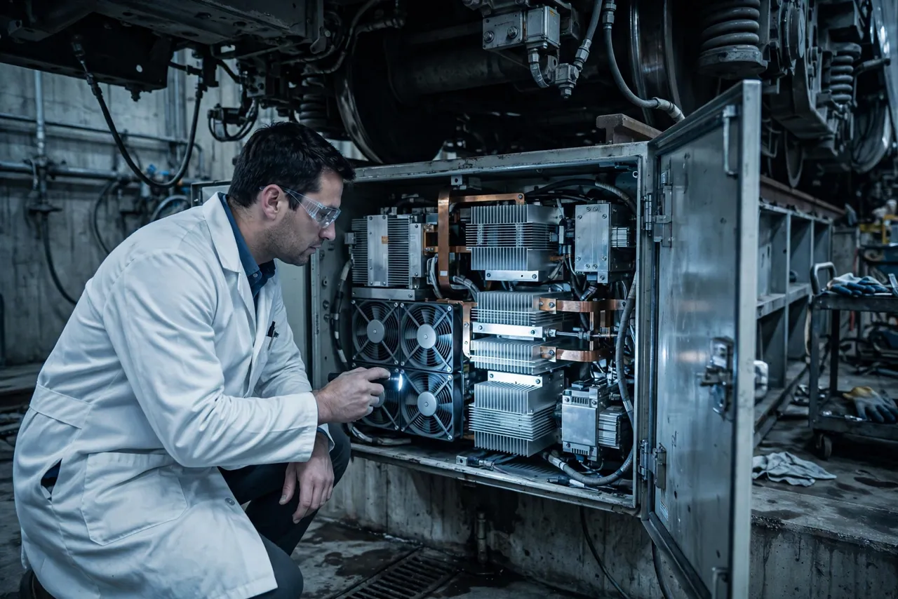
A metro train loses traction power halfway through a tunnel section. The passengers wait in the dark while the driver resets the system — the traction converter’s thermal protection had tripped. Underfloor, in the heat of the tunnel and the dust of the track bed, the converter’s cooling could not keep the power modules within limits during a long acceleration phase. The reset worked. The timetable did not recover for an hour.
The slower version never makes the news: a fleet whose converters derate traction effort on hot days, adding seconds to every station-to-station run. Seconds become minutes across a timetable; minutes become a capacity problem the operator cannot buy its way out of. Nobody’s fan failed. The cooling system was designed for the catalog, not for the tunnel.
Rail traction is the harshest long-life thermal problem in this series: power electronics switching megawatts under the floor of a vehicle, shaken for decades per IEC 61373, breathing tunnel dust, swinging from winter cold to tunnel heat — and expected to run 25 to 30 years with minimal attention. This article explains the heat sources, the vibration reality, wide-temperature operation, the service-life math, four misconceptions, and five buyer checkpoints.

Where the heat comes from
Power modules, magnetics, braking energy — and tunnel air that is nothing like lab air.
The power modules: IGBTs or SiC MOSFETs switching traction current generate the dominant heat — conduction and switching losses concentrated in modules bolted to heat sinks or cold plates. Every acceleration dumps energy; every braking phase dumps it again through the brake chopper. The thermal load is not steady; it follows the timetable.
The magnetics and busbars: transformers, inductors, and high-current busbars add their share — less glamorous than the semiconductors, but real heat in the same enclosure, and heat that the cooling air must also carry away. Do not forget the braking resistors where they share the cooling path: during sustained braking they can dominate the enclosure’s heat load for minutes at a time, and the fans must clear that pulse without letting module temperatures ratchet upward run after run.
The tunnel and the track bed: the converter does not breathe clean lab air — tunnel air is warm (trains heat tunnels), the track bed throws up dust and brake particles, and summer pushes underfloor temperatures far above the weather report. The cooling system’s “ambient” is the worst point of the route, not the weather station.
Duty follows the timetable: rush hour means back-to-back accelerations with short dwells — the thermal equivalent of the welder’s duty cycle at fleet scale. The cooling system must handle the peak service pattern, not the average one, because the timetable does not average. Do the heat budget at the real operating point: maximum traction effort, hottest tunnel section, peak timetable, worst-case ambient. That is what the fans must move, every day, for decades.
Vibration: the IEC 61373 reality
Rail vibration is a qualification, not a background detail — and it attacks everything the fan depends on.
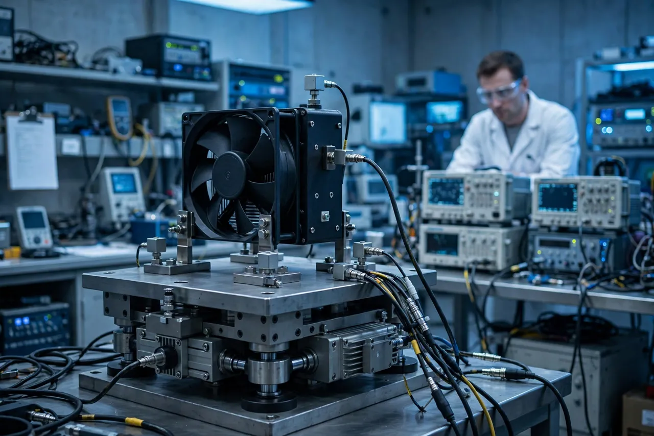
IEC 61373 defines the shock and vibration tests for railway equipment — random vibration spectra and shock pulses applied per axis, with the converter (and its fans) expected to survive and keep working. A fan that cools beautifully on a bench and dies on a bogie is a failed design.
What vibration does to fans: it loosens fasteners, frets connectors, fatigues solder joints and wire terminations, unbalances impellers over time, and wears bearings through micro-movements the datasheet never imagined. Each mechanism is slow; together over 30 years they are decisive. Shock pulses — from rail joints, switches, and the occasional hard coupling — add a different threat: single events that crack what vibration merely loosens, which is why the standard tests both.
Mounting is part of the fan: isolation mounts, locked fasteners, strain-relieved and secured wiring, connectors rated for the vibration class — the fan’s survival is decided by its installation as much as by its construction. Specify the mounting with the fan, validate them together, and never treat the fan as a drop-in part.
Test the assembly, not the component: a fan that passed vibration testing alone can still fail mounted on a resonant bracket inside a converter on a flexible underframe. Qualification must cover the installed configuration — the same lesson as the automotive article’s installed-configuration testing.
Wide temperature: from winter siding to summer tunnel
Cold start and tunnel heat — the cooling system must handle both ends, because the vehicle sees both.
The range is brutal: a vehicle parked overnight in winter cold, then running hard in a summer tunnel — the converter’s cooling system sees the full swing. Cold start means stiff bearings, brittle materials, and condensation risk; hot running means maximum thermal load with minimum air density for cooling.
Cold is not the absence of a problem: lubricants thicken, plastics embrittle, and moisture condensed during the cold soak becomes a short-circuit risk at power-up. Fans must start reliably at the minimum rated temperature — verified by test, not by assumption — and the control strategy must handle the warm-up transient. Bearing lubricant choice and motor starting torque at low temperature deserve explicit attention in the specification, because a fan that will not start in winter is a converter with no cooling when the timetable needs it.
Heat derating is a timetable problem: a converter that derates traction effort in tunnel heat does not just run warm — it slows the train, stretches dwells, and degrades the timetable. Thermal headroom in the cooling system is timetable resilience.
Design for both ends: specify the fan’s operating temperature range against the vehicle’s real extremes (including the tunnel delta), validate cold start and hot running, and protect the electronics against condensation across the swing.
The 30-year service-life math
The vehicle outlives every fan — so plan the replacements before the first one is installed.
A 25-to-30-year vehicle life means the cooling fans will be replaced several times — plan for it. The honest math: fan L10 life at the real operating temperature and duty, divided into the vehicle life, gives the replacement count. That count, times the cost of an underfloor service visit, is the cooling system’s lifetime service cost. Run this calculation during selection, not after the first in-service failure — it is the TCO article’s framework applied to the longest-lived equipment in the series.
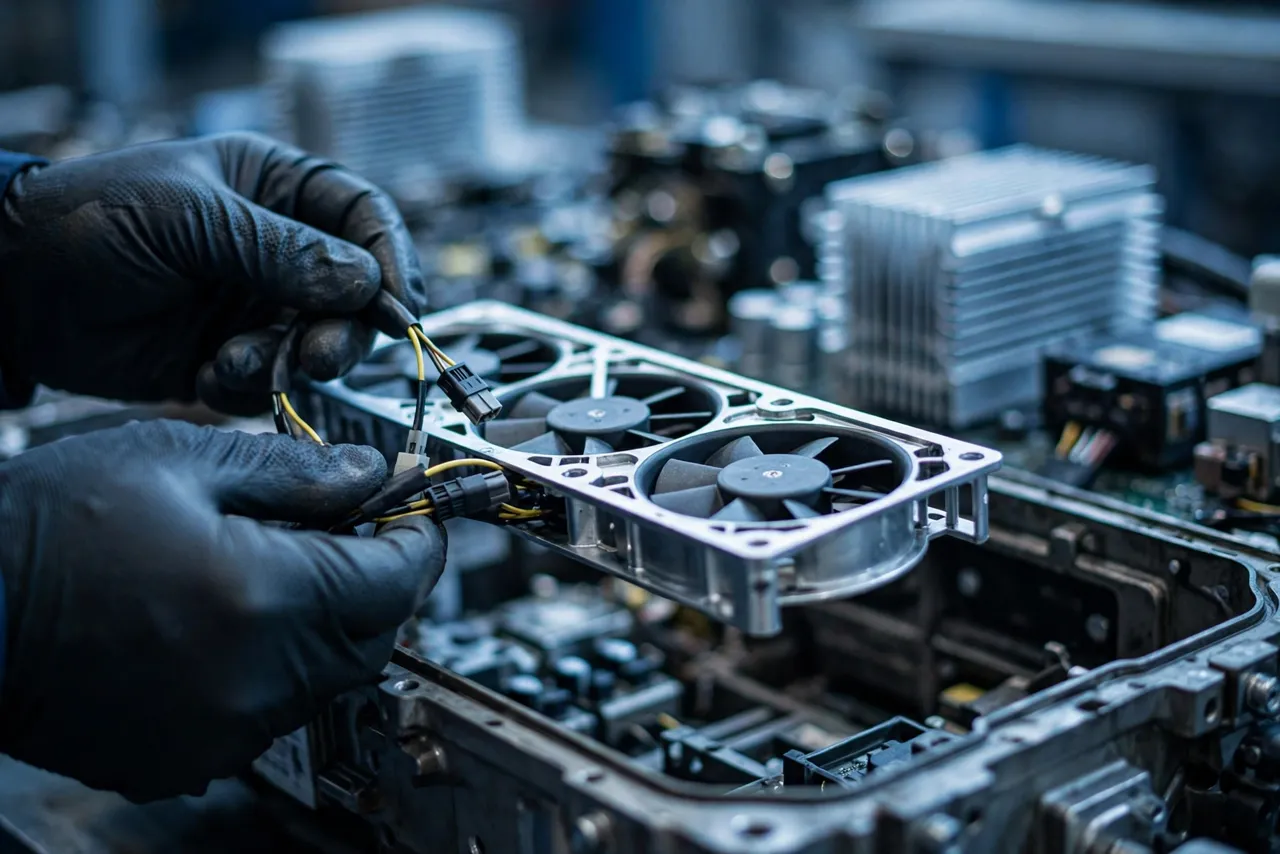
Design for replacement: fans buried behind power modules, requiring converter removal for a swap, turn a cheap part into an expensive outage. Accessible fan trays, quick-disconnect wiring, and replacement without special tools are not conveniences — they are lifecycle cost controls. Every minute of depot time has a price; multiply it by the fleet size and the replacement count, and accessibility becomes a specification, not a preference.
Obsolescence is a real risk: a fan model discontinued in year 12 of a 30-year vehicle life forces requalification of the replacement — or a lifetime buy. Specify with the long view: second sources, form-fit-function commitments, or a planned requalification budget.
Monitor to predict: fan speed, current draw, and temperature trending turn surprise failures into scheduled replacements. On a fleet scale, the data pays for the sensors many times over — the same telemetry argument as the AAU discussion, with decades to amortize it.
Four misconceptions that strand trains
The four beliefs that survive every design review — and keep timetables slipping every summer.
Misconception 1: “Rail-rated means thermally rated.” A fan can pass vibration qualification and still be thermally undersized for the tunnel — the two qualifications answer different questions. Demand both, validated together in the installed configuration.
Misconception 2: “The tunnel is just warm air.” Tunnel air is warm, dusty, and full of brake particles — it clogs filters, coats heat sinks, and degrades cooling over time. The thermal design must include the fouled condition, not just the clean one.
Misconception 3: “Derating protects the converter.” Derating protects the hardware while punishing the timetable — it is thermal protection doing its job and the cooling design failing at its. Every derating event is a service quality failure, even when nothing breaks.
Misconception 4: “Maintenance will catch fan degradation.” Underfloor converters on a running fleet get serviced on schedule, not on condition — and a degrading fan looks fine until it does not. Design for the maintenance interval you have, monitor for the degradation you cannot see, and make replacement easy for the day it comes.
Five buyer checkpoints for traction converter cooling
Five questions that turn “rail rated” from a slogan into a specification.
Checkpoint 1: demand the timetable heat budget. Power module losses at maximum traction effort, magnetics and busbar heat, hottest tunnel section ambient, peak timetable duty — in one documented budget. If the duty cycle is “average,” the budget is fiction. Checkpoint 2: confirm vibration qualification of the assembly. IEC 61373 testing of the fan in its mount, in the converter, on the vehicle interface — not just the fan alone on a shaker table. Ask for the test report at the assembly level.
Checkpoint 3: verify the temperature extremes. Cold start at the minimum rated temperature (tested, not assumed) and full-load running at the maximum tunnel ambient. Both ends, documented. Checkpoint 4: check the service-life plan. Fan L10 life at real operating conditions, replacement count over the vehicle life, accessibility of the fan for replacement, and the obsolescence strategy. A cooling system without a 30-year plan is a 10-year cooling system.
Checkpoint 5: require dust and fouling margin. Cooling performance with filters loaded and heat sinks fouled to end-of-interval condition — validated, not calculated. The tunnel always wins against clean-lab assumptions.
The design details that decide decades
Redundancy, ingress protection, corrosion, bearings, wiring — the details that compound over 30 years.
Redundant or monitored fan configurations: where the converter’s criticality justifies it, N+1 fan arrangements turn a fan failure into a maintenance ticket instead of a stranded train. Where redundancy is not justified, monitoring must be — speed and current trending with alarms.
IP rating matched to the underfloor reality: dust and water spray under the floor demand real ingress protection — but remember the IP-versus-airflow trade-off from the outdoor-display article: every point of sealing must be paid for in the thermal design. Corrosion and condensation protection: conformal coating on control electronics, drainage, materials rated for the humidity and salt exposure of the routes served. Thirty years of condensation cycles corrode what one year cannot.
Bearing and motor selection for the long haul: long-life bearing systems, motors rated for the temperature range with margin, and locked-rotor and thermal protection that fail safe. The fan’s weakest link sets the replacement interval — find it in design, not in service. Wiring for vibration: secured harnesses, strain relief at every termination, connectors with positive locking rated for the vibration class. In rail service, wiring fails before electronics — route and secure it like it matters, because it does.
How MEGA Tech supports traction converter projects
The winners design the cooling around the vehicle life — not around the catalog.
Rail projects punish catalog fan selection — the winners design the cooling around the vehicle life. MEGA Tech supports traction thermal projects through its standard five-step engagement: custom cooling fan development and manufacturing, fan selection, airflow path review, sample validation, and mass production.
In practice: selection starts from the timetable heat budget and the IEC 61373 vibration class (Checkpoints 1–2), so the fan matches the thermal and mechanical reality; airflow path reviews cover the converter enclosure including filter and fouling pressure drop at end-of-interval condition; sample validation tests the installed assembly — vibration plus thermal, cold start plus hot running; and mass production holds the validated configuration steady with change control across the vehicle’s long production run.
Engineer FAQ
Short answers to the questions buyers actually ask.
Q: Which vibration standard applies to converter fans? A: IEC 61373 governs shock and vibration testing for railway equipment — but the fan must be qualified in its mount and in the converter assembly, not just alone. Ask for assembly-level test reports.
Q: How do we handle tunnel dust in the thermal design? A: Size the cooling for the fouled condition — loaded filters, coated heat sinks at end-of-maintenance-interval — and validate it. The tunnel always degrades clean-lab performance; the design must survive the degradation.
Q: Our converters derate on hot days but keep running. Is that acceptable? A: It protects the hardware while degrading the timetable — seconds per run become a capacity problem across the schedule. Fix the thermal design; do not normalize the derating.
Q: How often will the fans need replacing over 30 years? A: Divide the fan’s L10 life at real operating temperature and duty into the vehicle life — that is the replacement count. Then make sure each replacement is accessible, quick, and planned, not an emergency.
Q: Do we need redundant fans? A: Where a converter failure strands a train, N+1 turns a fan failure into a maintenance ticket. Where redundancy is not justified, monitoring with speed/current trending and alarms is the minimum.
Q: What about obsolescence over 30 years? A: Plan for it now: second sources, form-fit-function commitments, or a lifetime buy with a requalification budget. A fan discontinued in year 12 without a plan is a project risk, not a purchasing problem.
Questions for your next design review
Bring these to the review; leave with a thermal design you can defend.
- Do we have a timetable heat budget — module losses, magnetics, tunnel ambient, peak duty?
- Is the fan qualified per IEC 61373 in its mount, in the converter assembly?
- Is cold start tested at minimum temperature, and hot running at maximum tunnel ambient?
- What is the fan L10 life at real conditions — and the replacement count over the vehicle life?
- Can the fans be replaced without removing the converter or special tools?
- Is there redundancy or monitoring — and what happens on a fan failure?
- Does the thermal design survive the fouled condition at end-of-maintenance-interval?
- What is the obsolescence plan for a 30-year vehicle life?
