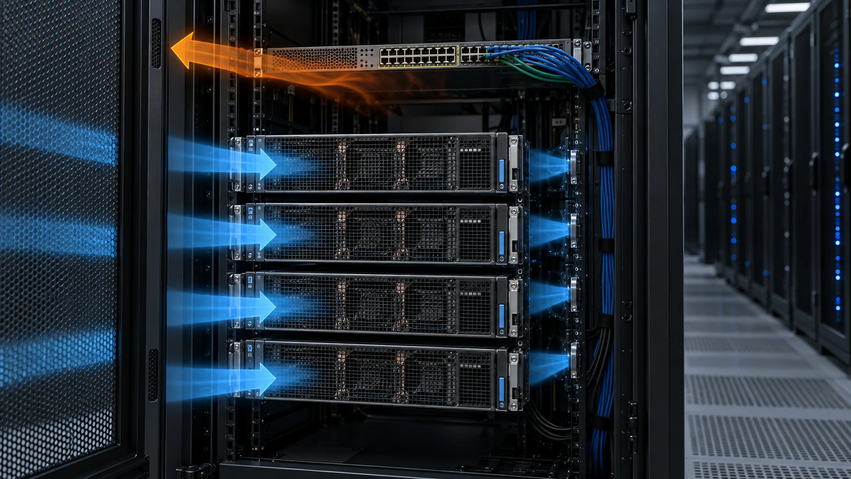
Liquid cooling changes the heat route
As accelerator heat loads rise, liquid can move heat near the processor through cold plates, manifolds, pumps and distribution equipment — but it is an architecture decision, not just a different heatsink.
Direct-to-chip (DLC) cooling places a cold plate on the highest heat flux components — GPUs, CPUs, HBM and voltage regulators — and carries the heat into a conditioned liquid loop instead of the room air. The practical question is not air versus liquid; it is which loads use each path, how the boundaries connect, and how the final rack stays serviceable and safe.
The physics behind the switch is volume. Water carries roughly 3,500 times more heat per unit volume than air at the same temperature rise. For a concrete liquid-cooling reference, OCP guidance uses about 1.25–1.5 litres per minute per kilowatt of cold-plate load, with a typical 10°C liquid temperature rise. Air-side requirements are not one universal CFM-per-GPU number: OCP's own comparison uses 0.145 CFM/W under stated dry-air and supply-temperature assumptions. Moving litres instead of large air volumes can shrink the distribution system, cut fan power and lower noise, but the actual result depends on the complete rack and facility design. Coolant stays inside the sealed cold-plate assembly and its connected loop; it does not touch the die.
There is no universal rack-density crossover because the answer depends on component power, inlet temperature, chassis geometry, water temperature, heat-capture ratio and facility limits. Published examples show the range: rear-door products are available in the tens of kilowatts per rack, while current liquid-cooled AI systems operate at much higher rack powers. NVIDIA documentation lists approximately 120 kW for a DGX GB300 NVL72 rack, and the OCP liquid-cooling specifications define PG25-based liquid loops with 1.25–1.5 LPM/kW design points. The rack density and validated thermal envelope — not preference — set the method.
Air cooling remains inside the chassis
Even a liquid-cooled server keeps components that need airflow: memory, network devices, power supplies and other surfaces not directly coupled to the liquid loop.
Cold plates capture the heat from the components they actually cover; the remaining DIMMs, NICs, storage, motherboard and PSU losses stay on the air path. Use the capture ratio as a measured specification, not a universal 70–80% assumption. For example, a 30 kW rack at 80% liquid capture leaves 6 kW of air load. A 130 kW rack at 75% capture leaves 32.5 kW on the air path. The arithmetic is simple; the design value must come from the chosen server configuration and maximum validated workload.
That is why the heat-capture ratio should be treated as a specification to verify, not an assumption. Procurement guidance circulating in the AI-campus market is blunt: require the server supplier to state the liquid heat-capture ratio under maximum validated workload, tied to a specific server configuration rather than a general platform family. A 30 MW IT block at 80% capture means 24 MW of liquid load and 6 MW of residual air load — and that 6 MW still needs fan walls, in-row units, rear-door exchangers or another engineered air path.
Compact fans and a controlled enclosure path stay essential. Liquid cooling does not remove the need to manage grille restriction, bypass flow, component zoning and residual chassis heat — it moves those requirements to a smaller, easier-to-ignore fraction of the rack, which is exactly why they get overlooked. Size the chassis fans for the worst case (sustained full-power training), not the average utilisation, because thermal events concentrate precisely when the cluster is earning revenue.
The two linked loops
A hybrid rack carries heat on two coupled paths: a secondary liquid loop to the cold plates and an air path for the residual.
The secondary (technical) loop circulates conditioned coolant from a Coolant Distribution Unit (CDU) through a rack manifold to the cold plates, then back to the CDU's liquid-to-liquid heat exchanger. The CDU isolates that clean loop from facility water, and monitors pressure, flow, temperature and filtration. A worked example: a 120 kW rack with 80% liquid capture moves about 96 kW through the loop; using water-like specific heat and a 10°C rise, that is roughly 2.3 kg/s (≈8.3 m³/h) of coolant. The Open Compute Project gives about 1.5 LPM per kW at a 10°C rise as a reference target for a specified PG25 cold-plate design; it is not a universal setpoint for every coolant or rack.
The coolant itself is specified more tightly than most first-time builders expect. OCP liquid-cooling specifications use PG25-based fluid as a reference for several cold-plate platforms, with nominal supply temperatures and flow limits stated for the specific design. One OCP example targets a 10–12°C liquid-side rise, equivalent to about 1.25–1.5 LPM/kW. Do not transfer the chemistry, freeze protection, inhibitor package or pH range from one platform to another: follow the cold-plate, CDU and coolant supplier's compatibility specification for the complete wetted path. Going richer in glycol changes specific heat, viscosity and pressure drop, so it is a design choice to validate rather than an automatic improvement.
The air path is the residual trim. It is often a rear-door heat exchanger or in-row unit sized for the measured residual load, not automatically for a fixed percentage of the rack. At the server boundary, dripless quick-disconnects on the rack manifold let a server slide in and out without draining the loop; pressure rating and allowable pressure drop are connector- and platform-specific. Because the two loops meet at the rack, the manifold balance, the CDU pressure budget and the air trim must be specified together — not bought separately and hoped to agree.

Define responsibilities at each layer
A useful brief separates the server-side fan requirement from the liquid-loop requirement so neither owner over-promises.
This prevents a compact-fan supplier from being asked to promise a complete liquid system, and prevents a liquid-system project from overlooking the internal air path that still sets component temperatures. The boundary is practical: the cold plate, manifold, CDU and facility heat rejection are one scope; the enclosure airflow that serves the non-liquid components is another.
The interface between rack and facility has a vocabulary worth using in the brief: the ASHRAE liquid-cooling classes. The fifth-edition Thermal Guidelines (2021) define facility supply-water classes W17, W27, W32, W40, W45 and W+ — the number identifies the nominal maximum facility supply temperature for the class. Condensation control is a separate requirement: ASHRAE TC 9.9 recommends maintaining facility water at least 2°C above the room dew point in the relevant non-CDU designs. Warmer coolant can improve economizer opportunities, but it carries less heat per unit of flow and may require more capable plates, pumps and exchangers. The number that connects the two worlds is the CDU approach temperature: facility supply class plus CDU approach determines the technology-cooling supply the plates actually see.
Two more contract lines belong in the brief. First, warranty boundaries: server OEM, cold-plate kit, CDU and facility providers each cover a slice, and an ambiguous wetted-path ownership is how leak damage becomes a legal dispute. Second, material compatibility: mixed metals and incorrect elastomers across cold plates, hoses, fittings, CDU internals and facility piping create corrosion and permeation risks, so the entire wetted path should be verified as one system, not component by component.
MEGA can support compact fan selection and a custom fan configuration review for the air-side residual — grille, bypass and zoning inside the chassis. The liquid distribution, rack integration and facility heat-rejection scope should be confirmed with the specialist partner responsible for those systems.
Design for the fallback, not just the rating
Hybrid cooling is judged by its degraded states: what happens when a door opens or a loop is lost.
Two fallbacks decide whether the design is real. First, when a rear-door HX is open for service, the air-cooling system must carry the full rack load, not just the residual fraction — so in-row or CRAH capacity has to be planned for the defined maintenance condition. Second, a CDU outage can remove liquid cooling from a rack or row quickly; production designs commonly use N+1 CDUs, cross-tied manifolds or controlled load shedding. The required ride-through time is a project requirement to calculate and test, not a universal 60–120 second value.
CDU capacity itself deserves scrutiny at real operating conditions. Industry procurement guidance makes the point sharply: usable capacity is not the nameplate divided by IT load — it depends on facility-water temperature, technology-loop supply temperature, heat-exchanger approach, coolant properties, available pump head and exchanger condition. A fleet described as "20% oversized" is not automatically N+1: if one unit fails at peak, the survivors must still satisfy flow, pressure and temperature simultaneously. A serious CDU specification states guaranteed capacity at design conditions, minimum and maximum flow, pump and electrical redundancy, filtration and air-removal, expansion and pressure control, leak detection, sensor calibration, and local control behaviour when the BMS link drops.
Zoning is the other half of failure containment. A campus-wide cooling loop is one enormous common failure domain; the practical alternative is repeatable capacity blocks, each with isolation valves, bypasses, drains, fill points and its own leak-detection coverage — so a failed pump or controller cannot cascade across zones. The subtle version of this mistake is electrical, not hydraulic: controls and power common points can defeat an apparently redundant plumbing layout.
Some cold plates can switch to an air-fin fallback at reduced power, letting the rack derate rather than fail — but derate means lower density, not business as usual. Do not use a generic annual leak-rate target as proof of safety; specify leak sensing at low points and under manifolds, flow and pressure sensing that identifies abnormal behavior, and a coolant chemistry that makes the maintenance response clear. Name the trip and advisory logic, the owner of each excursion, and the commissioning measurement that proves the fallback before the rack is accepted.

Prototype the hybrid system honestly
Validate with the intended cold plates, covers, tubing routes and populated components — not an idealised subset.
Removing the air-cooling restrictions or testing only the liquid loop can hide a local hot spot that remains in the production server. The classic loop failures are not silicon failures: an incorrectly positioned valve, flow imbalance across parallel cold plates, air in the secondary loop, particulate or chemistry drift, and quick-disconnect leaks during service.
Measure the components served by air and liquid separately, and pressure-test the secondary loop according to the applicable component, hose and site safety requirements before IT lands. The commissioning pack should verify the liquid heat-capture ratio at maximum validated workload against the supplier's figure, flush and filter the loop before fill, establish a coolant sampling and top-up schedule so chemistry stays inside specification, and re-check quick-disconnects after the first thermal cycles. This identifies whether an airflow issue, a liquid-loop issue or an interface issue is limiting the result — and gives the operations team the handover pack they need.
For calibration on what mature operation looks like, published deployments are instructive but not interchangeable. NREL reports that its ESIF HPC facility regularly uses about 3% additional energy for cooling, while LLNL describes El Capitan using warm water at about 85°F to avoid energy-intensive refrigeration. Those are site-specific outcomes, not commercial guarantees. The transferable lesson is that the liquid loop can do the heavy lifting when the facility water, controls and heat rejection are designed together; the air side is still deliberately engineered, not assumed away.
Customize the air-side sample around the hybrid rack
Liquid cooling removes part of the heat, but the remaining air path still needs a fan that fits the real rack.
A hybrid rack creates a specific fan requirement: the air-cooled memory, power supplies, storage, network interfaces and other residual loads may need different airflow and pressure than a conventional server. MEGA Tech can help define that air-side requirement around the actual rack, including residual heat load, available space, grille and filter losses, noise limit, voltage, control signal and service conditions.
The fan configuration can be adjusted for frame size and thickness, speed range, airflow and static pressure, PWM control, FG or RD feedback, connector and cable length, bearing choice, rotation direction, mounting and environmental protection. If the standard catalogue option does not match the hybrid enclosure or the required fallback condition, we can develop a customized sample and test it with the representative cold-plate covers, manifold routing and air-side restrictions.
Validation should cover normal liquid operation, higher residual air load, door-open or liquid-loop fallback conditions and the customer's actual control response. We check temperature rise, pressure margin, noise, signal behavior and continuous operation, then refine the sample with the hardware team. The approved configuration can move from an early small build into reliable volume production without treating the air side as an afterthought.
- Separate liquid-captured heat from the residual air-side heat load.
- Customize fan size, pressure, control, feedback, wiring and mounting around the rack.
- Test normal and fallback conditions with representative liquid and air interfaces.
- Move the validated configuration into stable, repeatable production.
Why air cooling still belongs in the design
Air cooling is not the part liquid replaces; it is the part that stays, shrinks, and becomes the safety margin.
Three reasons keep it in the design. Residual components must be air-cooled regardless of how good the cold plates are. The air path is the maintenance and failure fallback above. And at lower or mixed rack densities, air cooling or air plus a rear-door HX may remain the practical choice, so mixed-density halls need both skills at once — liquid-cooled AI rows commonly sit beside air-cooled storage, networking and general-purpose rows.
Operationally, DLC changes the air job for the better, but the measured temperatures and performance depend on the server, cold plate, coolant temperature, workload and control limits. Higher facility-water temperatures can also expand economizer or dry-cooler opportunities, but only when the facility heat-rejection design supports them. Even for the air-cooled remainder, ASHRAE's H1 high-density class uses a recommended inlet band of roughly 18–22°C, tighter than the classic A-class 18–27°C guidance. That is a useful design reference, not a universal setpoint.
The economics explain why hybrid, not pure liquid, is often the landing point for operators. Project cost and payback vary with rack density, CDU and piping scope, facility-water temperature, energy tariff and workload. Keeping a well-engineered air path for the residual, the fallback and mixed-density rows is usually the more resilient architecture. The fans get smaller and quieter — they do not disappear.
Engineer FAQ: Hybrid Liquid and Air Cooling for AI Racks
Liquid cooling changes the heat path, but the remaining air load, fallback state and fan interface still require their own measured design case.
Q: Does direct-to-chip liquid cooling remove the need for server fans? A: No. Cold plates remove heat only from the components they cover. Memory, networking, storage, power supplies, motherboard losses and other surfaces may remain air-cooled, so the residual air load and its chassis pressure drop must be specified and validated.
Q: Is there a universal liquid flow rate or heat-capture percentage for every AI rack? A: No. Values such as 1.25–1.5 LPM/kW, a 10°C liquid rise or 70–80% liquid capture are platform-specific references or examples. Use the selected cold plate, coolant, CDU, server configuration and validated workload to establish the actual flow, pressure and capture ratio.
Q: How should the residual air-side fan be selected? A: Separate the heat that enters the liquid loop from the heat remaining in the air path, calculate a first airflow target from the residual heat load and allowed temperature rise, then solve the fan P-Q curve against the populated chassis, grille, filter, heatsink and cable resistance. Check the actual inlet temperature and control range.
Q: What does the CDU specification need to include? A: At minimum, define guaranteed capacity at the facility-water and technology-loop temperatures, approach temperature, flow and pressure curves, coolant properties, pump and electrical redundancy, filtration, leak detection, connector interfaces, control behavior and the response to sensor or BMS communication failure. A nameplate kW value alone is not enough.
Q: How should a hybrid rack handle a liquid-loop or rear-door failure? A: Define the fallback before procurement. Examples include higher air-side operation during a door-open service event, controlled rack derating after CDU loss and isolation of a leak zone. The required ride-through time and allowable temperature are project requirements that must be tested, not assumed from a generic value.
Q: Is keeping the coolant above the dew point sufficient to eliminate condensation risk? A: It is an important control condition, not the whole safety case. Account for sensor error, local cold spots, fittings, insulation, humidity excursions and control response. Verify the relevant loop and exposed components at the real facility temperature band, with leak and dew-point alarms tested.
Q: Why must liquid and air measurements be correlated? A: Water-side heat balance can look correct while bypass air, uneven cold-plate flow or warm recirculated air leaves components too hot. Correlate coolant flow and temperatures with rack inlet, exhaust, component temperatures, airflow, pressure and workload so the limiting path is identified.
Q: When should a customized compact fan sample be developed for a liquid-cooled server? A: When residual heat, chassis space, pressure drop, noise, voltage, PWM/FG/RD behavior or fallback duty cannot be met together by a catalogue row. Test the sample with representative cold-plate covers, manifold routing, grilles, filters, firmware and both normal and fallback conditions before production.
- Tie every numerical answer to voltage, speed, temperature, mounting and test condition.
- Separate catalogue maximums, engineering estimates and measured application results.
- Use the FAQ to define the next measurement or sample-validation step.
Hybrid cooling review
One review connects the thermal layers and the owners.
Use the checklist below at design review. It is the same list that prevents the silent failures: a residual air load assumed away, a CDU sized without its own redundancy, a capture ratio that exists only in a brochure, or a fan supplier expected to cover a liquid system.
- What is the verified liquid heat-capture ratio of the chosen server configuration at maximum validated workload — and the residual kW at full load?
- Which loads use liquid and which retain air cooling, and who specifies the compact fans for the air path?
- Which ASHRAE W-class does the facility water target, and what CDU approach temperature does that imply for the technology loop?
- What coolant chemistry (for example PG25) is specified, and who owns sampling, top-ups and wetted-material compatibility across the whole path?
- Where are likely bypass paths, local hot spots and manifold flow-imbalance risks?
- What service and fault conditions must the rack support (door-open 100%, CDU loss, leak detection zones, derate behaviour)?
- Are CDUs guaranteed-capacity sized at design conditions with N+1 — and does the hydraulic zoning prevent one failure from cascading?
- Which partners own server, rack and facility interfaces — and who holds the fallback?