Separate server cooling from facility cooling
Before comparing DC and EC fans, fix which thermal layer you are talking about.
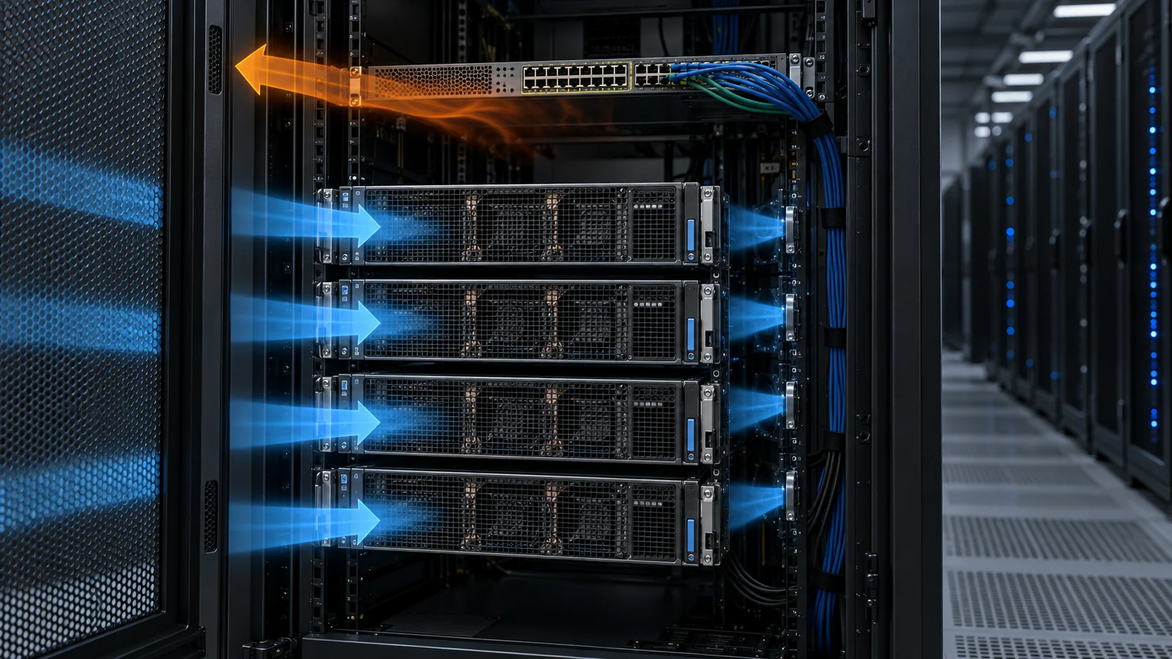
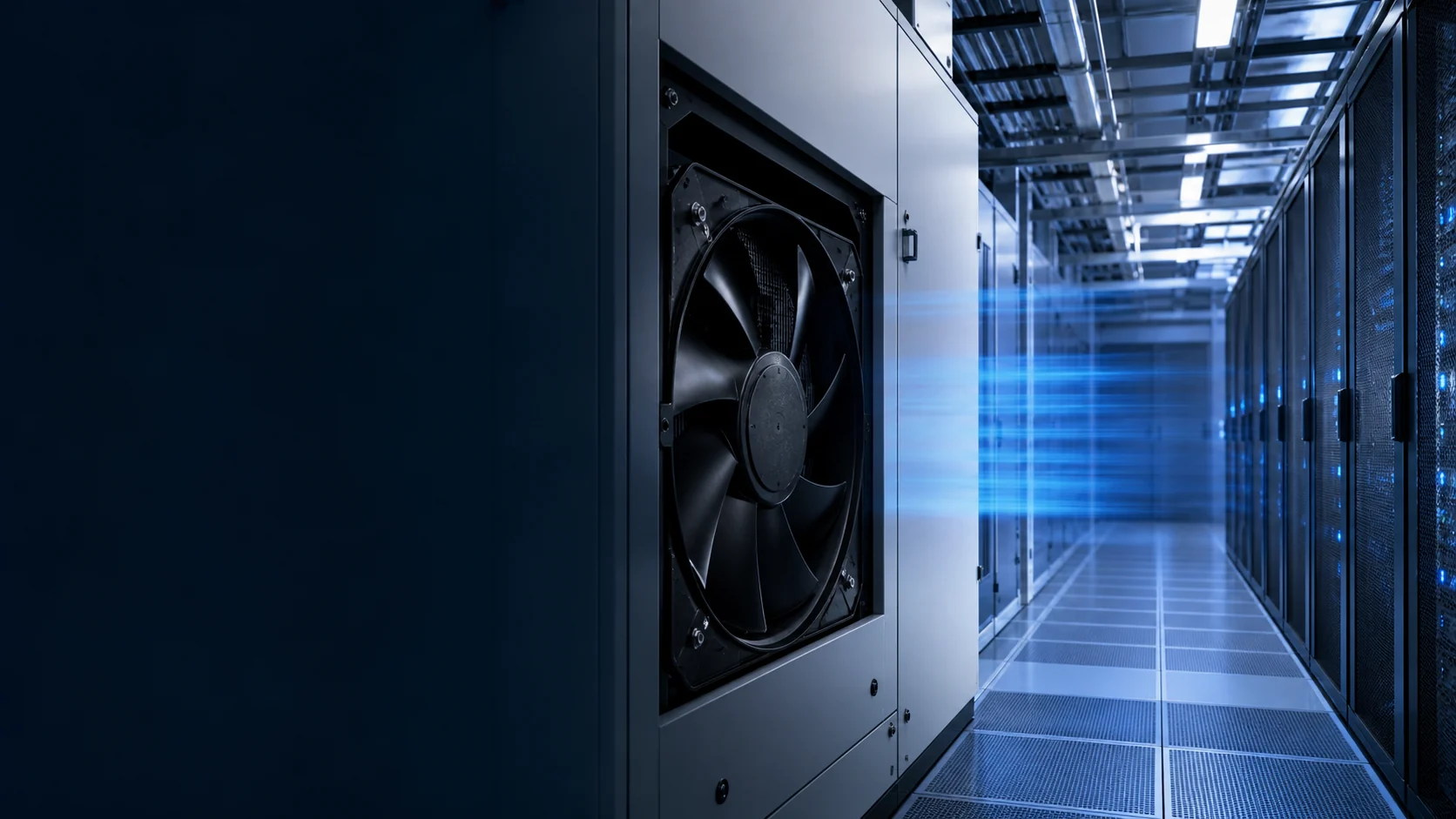
AI data center cooling is a layered system. At the server level, compact DC axial fans push air through the chassis, across GPU heat sinks and through the power shelf. At the facility level, larger air-handling equipment — CRAH and CRAC units, in-row coolers, rear-door heat exchangers, cooling distribution units — moves air through the room, row or rack. EC fan assemblies are most often proposed for that facility layer, although smaller electronically commutated assemblies can also appear in equipment; the electrical interface, pressure range and validation method decide the relevant comparison.
The two layers differ in almost every selection parameter. A server fan moves tens of CFM against a few millimetres of water pressure inside a 25 mm-thick envelope; a facility fan moves thousands of CFM against hundreds of pascals across coils and ductwork. One is chosen by a hardware thermal engineer who owns the board-level air path; the other is chosen by a facility or mechanical engineer who owns the room air path. The contracts, the validation data and even the failure vocabulary differ.
That ownership split is also why the 'DC versus EC' question so often produces two correct, contradictory answers in the same meeting. The IT hardware team is right that their brushless DC fans are already electronically commutated. The facility team is right that their belt-driven or line-frequency AC units are the least efficient moving parts in the building. Both statements are true because they are talking about different layers.
The pressure regimes alone keep the layers apart. A chassis fan fights a few hundred pascals across heat sinks and cables; a CRAH fan must overcome a coil, filters and plenum geometry that can sum to well over a kilopascal. Rise an order of magnitude in pressure and every design habit changes: bearing size, blade solidity, motor cooling, surge margin and even how vibration is measured. A component optimized for one regime is simply not a candidate in the other.
The first engineering question is therefore not 'DC or EC'. It is which thermal layer is being discussed, what pressure and volume that layer demands, and who validates it. Mix the two up and the rest of the comparison is meaningless.

Why variable speed is worth the complexity
Fan power scales with the cube of speed — so matching airflow to demand is where the savings live.
Compute load, server population and ambient temperature all swing over a day and a year. A speed-controllable fan matches airflow to a measured target instead of running permanently at a conservative maximum.
The physics is useful but conditional: when the fan geometry, air density and operating regime remain comparable, fan-law estimates make power scale roughly with the cube of speed. Halving speed predicts about one-eighth the fan power under the constant-efficiency approximation. The full affinity chain matters when you sanity-check a proposal: airflow scales linearly with speed, static pressure with the square, and power with the cube. A unit slowed to 80% speed predicts about 80% of the airflow, 64% of the pressure capability, but only about half the power. At 60% speed, pressure capability is barely a third of maximum — which is why part-load claims should always be quoted together with the duct system curve and the measured wire-to-air input power.
Run the cube law against a realistic duty profile and the savings stop being abstract. Under the constant-efficiency approximation, a unit at 70% speed consumes about 34% of the full-speed fan power. That is an engineering estimate, not a promise: motor, controller, system resistance and minimum-speed limits change the installed result. A U.S. Department of Energy data-center case study gives a measured-style example of 6.5 kW at full speed versus about 3.3 kW at 80% speed, consistent with the cube-law estimate. Because facilities are engineered for worst-case density that may occur only part of the year, the part-load region is exactly where variable speed can pay back. Lower speed also reduces the fan's acoustic output, subject to the installed system and measurement method.
Speed control also unlocks control strategies a fixed-speed fan cannot support: staging units against a cold-aisle temperature setpoint, riding through morning warm-up at reduced flow, or trimming airflow when economizer conditions let the coils run warmer. Those strategies are worth more than the motor swap alone.
But speed control is only a saving if the surrounding system is designed for it: sensors, control logic, a safe minimum speed, fault behavior and commissioning criteria all have to be defined before the control becomes a reliable energy or acoustics strategy.

EC versus AC: what actually changes inside the fan
An EC fan is a brushless DC motor with integrated AC-DC conversion and onboard control.
A conventional AC fan uses an induction motor fixed to the line frequency unless a VFD or another speed-control method is added. It may be throttled with a damper or inlet device, but that can waste pressure energy. One manufacturer comparison gives indicative AC and EC motor-efficiency ranges, but those figures should not be copied into a project budget: actual complete-fan efficiency depends on the fan, motor, controller, operating point, air density and test method. Compare measured wire-to-air input power at matched airflow and pressure.
An EC (electronically commutated) fan pairs a brushless permanent-magnet motor with an integrated electronic controller and, in many products, an AC input stage. The electronics control speed without line-frequency lock, so variable-speed operation can follow the load more directly. The efficiency advantage is a reference point, not a universal rating: compare complete wire-to-air input power and the P-Q curve at the duty point you will actually use.
Two second-order effects matter in a facility power budget. First, power quality: EC units present a controlled electronic load, and reputable ones publish input harmonics (THD) and power factor across the operating range — worth checking against your UPS and PDU environment. Second, starting behavior: many EC fans ramp electronically and may reduce or shape the input transient compared with a line-started AC motor, but the selected unit's inrush, protection and ride-through behavior still need to be verified.
Put the economics into a transparent calculation instead of repeating a universal payback claim. If two complete fan assemblies differ by 2.07 kW at the same required duty, and the fan operates 8,760 hours per year at $0.10/kWh, the gross electricity difference is about $1,813 per year before cooling-system overhead, maintenance, tariff and actual part-load operation. That is an example calculation, not a product comparison; the vendor's measured input-power curve must supply the real values.
The honest caveat is serviceability. EC electronics are one more component with firmware and capacitors, and a failed control board means a spare-parts and diagnostics conversation that a plain induction motor never has. Ask any vendor how failure is indicated, how the unit degrades, and what the replacement procedure looks like before comparing nameplate efficiency.
Don't compare a room fan to a server fan
A chassis fan and a facility fan solve different problems and are not interchangeable.
A compact fan inside a server is selected around a tight mechanical envelope and a tightly defined electronics air path: it must clear the heat sinks, survive the PSU shelf, and hold its rated pressure behind a loaded filter. Its selection language is millimetres of water, L10 bearing life at 40-70°C, PWM tach feedback and dupont-style connectors. Its redundancy model is implicit — dozens of small fans per rack, each covered by its neighbours.
A facility fan is selected around a duct, coil, plenum or rack environment, with different mechanical, acoustic and control interfaces. Its selection language is kilopascals, plug-fan diameter, BMS protocol support and access for service. Redundancy is explicit — N+1 arrays, fan walls with hot-swap cartridges — rather than emergent. Treating an EC facility fan as a substitute for the compact DC fans inside a chassis is a category error.
The acoustic contrast is easy to underestimate, too. Chassis fans produce a high-frequency whine that mostly dies inside the rack; large plug fans produce broad-band noise that propagates through the room and the structure. An EC retrofit changes the room's sound, and acoustically sensitive sites should treat that as a design input, not a surprise.
They can sit in the same data center while solving different parts of the thermal problem. The useful question is which one owns which layer.
Where EC fan assemblies actually sit in the cooling stack
Facility cooling is where EC fans earn their place.
CRAH and CRAC units: EC plug or mixed-flow fans move room air across the cooling coil. This is the classic, highest-volume application and the easiest place to retrofit an existing room — the unit frame stays, the fan deck becomes EC, and the BMS gains a real speed input. Verify the unit's coil face velocity after the change: slowing fans changes the coil's sensible-capacity curve, not just the power draw.
In-row and rear-door heat exchangers (RDHx): EC fans pull rack exhaust through the door or unit coil. Published capacity varies widely by door, coil and operating condition, so treat any 20-80 kW range as a design example rather than a universal rating. The fan sees the door coil's pressure drop, which rises sharply with airflow — so the honest selection point is the pressure at full rack load, not the door's open-area spec.
Cooling distribution units (CDU) and fan walls: at high density the air side still needs fans. CDU coils and N+1 fan-wall arrays may use high-static-pressure EC plug fans; a 1.5-3.2 kPa selection window can be a useful early design range, not a universal requirement. When you size the array, check that the surviving fans can actually reach the required duty on their curve — the cube-law power saving applies at normal operation, but the redundancy case lives at maximum speed.
Density trend: current rack-scale AI systems are already in the 100 kW class. NVIDIA's GB300 NVL72 documentation lists approximately 120 kW for the rack configuration and up to 142 kW for the full rack in its enterprise reference architecture. That architecture is liquid cooled, so at these densities the air side is downstream of the liquid-cooling decision; EC fans serve the air that remains around the rack and room — envelope loads, leakage, auxiliary electronics and residual heat — not the GPU die directly.
Containment interacts with every case above. A well-sealed cold aisle lowers the pressure the fans must produce; a leaking one silently forces them to higher speed, and the cube law then punishes the leakage in both power and noise. Walk the containment before blaming the fans.
Plan the maintenance story at selection time, not after the first failure. EC assemblies concentrate electronics, firmware and power components into a cartridge that is usually replaced rather than repaired — so the spare-parts list, the swap procedure and the diagnostic interface are procurement questions. A fan wall with hot-swap cartridges and a shelf of spares is a different operating model from a CRAH with a service contract; both work, but the facility team should know which one they are buying.
Control architecture needs a fault plan
Speed control is only as good as its degraded behavior.
A fan-control diagram should state what drives the speed request (a temperature sensor, a BMS setpoint, a schedule), how sensor inputs are filtered, what happens when a signal is missing, and what safe state the unit enters after a fault. Write it down before the equipment is ordered — most bad fan-control retrofits trace back to an undefined degraded mode, not a bad motor.
A workable loop is usually simple: one measured variable (supply-air or cold-aisle temperature), a PI controller, a speed request, and hard limits at both ends. The limits matter as much as the loop: a minimum speed floor keeps the motor and electronics within their thermal envelope and keeps airflow above the floor grilles' throw requirements; a maximum-speed ceiling protects acoustics and keeps headroom for the redundancy case.
Interfaces are typically 0-10 V, PWM, Modbus RTU or BACnet, integrated with the BMS or DCIM. On a bus protocol, ask specifically what happens when the heartbeat stops: does the fan hold last command, fall to a preset speed, or coast to a stop? Each answer is defensible somewhere, but the choice must be deliberate and tested. Sensor plausibility checks belong in the same conversation — a stuck 24.0°C reading that quietly holds fans at minimum is worse than an obvious failure.
For critical infrastructure the degraded condition matters as much as nominal efficiency. Commission the failure paths deliberately: pull a sensor, kill a comms line, trip one unit of an array, and confirm the room converges. Review it at the expected airflow resistance, not only at a manufacturer headline rating.
Bring the server fan requirement to a tested sample
When the requirement is inside the chassis, a compact DC fan must be developed around the real server air path.
The facility-level EC discussion should not hide the component decision inside the server. GPU servers, storage systems and power shelves still need compact fans matched to their own heat load, restriction, acoustic target and available space. MEGA Tech helps hardware teams turn those requirements into a practical fan specification rather than selecting from a free-air headline.
The review can cover frame size and thickness, rated voltage, speed range, airflow and static pressure at the actual operating point, PWM control, FG or RD feedback, connector and cable length, bearing choice, rotation direction and mounting details. If the standard configuration does not fit the chassis or the required performance window, we can adjust the fan around the product and build a sample for evaluation.
The sample should be tested in the representative server, duct, grille, filter and heat-sink path. We compare temperature rise, pressure margin, noise, control response and continuous operation, then refine the configuration with the customer. Once the result is approved, the same specification can move into reliable volume production, giving new AI hardware teams a realistic path from a small first build to repeat supply.
- Define the server heat load, pressure loss, noise limit and electrical interface.
- Customize the fan's size, speed, control, wiring and mounting around the chassis.
- Validate the sample in the real or representative airflow path.
- Transfer the approved configuration into stable, cost-conscious production.
Keep capability statements precise
This article explains a category; it is not a MEGA Tech EC product announcement.
The engineering lesson stands regardless of vendor: establish the system boundary, then ask the appropriate component or infrastructure partner to validate the part of the architecture they supply.
When you evaluate an EC option, ask for the measured P-Q curve, the efficiency map across speed, the control interface, the IP rating for the intended location, and the failure-mode behavior — not just a headline wattage. A credible supplier hands over the full curve set and lets your mechanical engineer pick the operating point; a marketing sheet that shows only the full-load wattage tells you the part-load story is not worth telling.
Treat the validation as a small procurement step, not a formality: one sample unit, one measured duty point on your duct system, one week of part-load data. That is usually enough to confirm or kill a manufacturer's part-load claim before it multiplies across a room.
Engineer FAQ: EC Fans for Data Center Cooling
EC selection starts with the cooling layer, the installed duty point and the control failure plan; efficiency alone is not enough.
Q: Is an EC fan a replacement for every DC server fan? A: No. EC and DC describe different implementation and system contexts in this article. A compact server fan must fit the chassis and its heatsink path; a larger EC assembly is usually evaluated for a CRAH, in-row unit, rear-door exchanger or fan wall. Match frame, pressure, airflow, control and service requirements to the layer.
Q: How should the energy benefit of an EC fan be compared? A: Compare complete wire-to-air input power at the same airflow, pressure, air density and operating condition. A motor-only efficiency number or a full-speed nameplate wattage cannot establish part-load savings. Include controls, standby power, harmonics, power factor, maintenance and the actual annual duty profile in the calculation.
Q: Can the fan-law cube relationship predict the exact power saving? A: It is a conditional estimate for comparable fan geometry, density and operating regime. Airflow, pressure and power do not automatically follow the ideal ratios after system effects, motor efficiency, controller losses and minimum-speed limits are included. Use the fan and system curves, then confirm with measured input power.
Q: What should be checked before connecting an EC fan to a BMS? A: Confirm the command interface such as 0-10 V, PWM, Modbus or BACnet, input range, signal reference, feedback meaning, minimum and maximum speed, start behavior, EMC requirements and the response to a lost command or communication heartbeat. Interface names alone do not prove compatibility.
Q: What happens if a temperature sensor or communication link fails? A: The safe response must be defined by the facility thermal and availability requirements. The controller may hold a verified fallback speed, move to a fixed safe state or raise an alarm, but the choice must be tested with a pulled sensor, invalid reading and lost communication rather than assumed from the datasheet.
Q: How should EC fan redundancy be validated? A: Test the required duty with one unit unavailable, the highest expected system resistance and the defined control response. Check airflow, room or rack inlet temperature, pressure, power, noise, alarms and recovery time. N+1 is not proved by the number of installed cartridges alone.
Q: When does the decision return to a customized compact DC fan? A: When the requirement is inside the server or power shelf and the limiting variables are frame space, heatsink pressure drop, PWM/FG/RD behavior, noise, voltage, connector or mounting. Build a representative sample and validate the populated chassis before carrying the approved configuration into volume production.
- Tie every numerical answer to voltage, speed, temperature, mounting and test condition.
- Separate catalogue maximums, engineering estimates and measured application results.
- Use the FAQ to define the next measurement or sample-validation step.
Questions for a design review
Make the cooling layer explicit before choosing anything.
A good review names the layer, the owner and the failure plan. The checklist below keeps an EC discussion honest and stops it from drifting into a chassis that should stay DC.
- Is the target a server, rack, row or room?
- What airflow and static-pressure condition exists there?
- Which measurement commands the fan speed?
- What are the minimum and maximum speed limits, and why those numbers?
- What happens after a sensor or fan fault?
- What does the bus protocol do when the heartbeat stops?
- Who owns installation, commissioning and long-term monitoring?
- Is liquid cooling already deciding the GPU die, leaving air for the periphery?