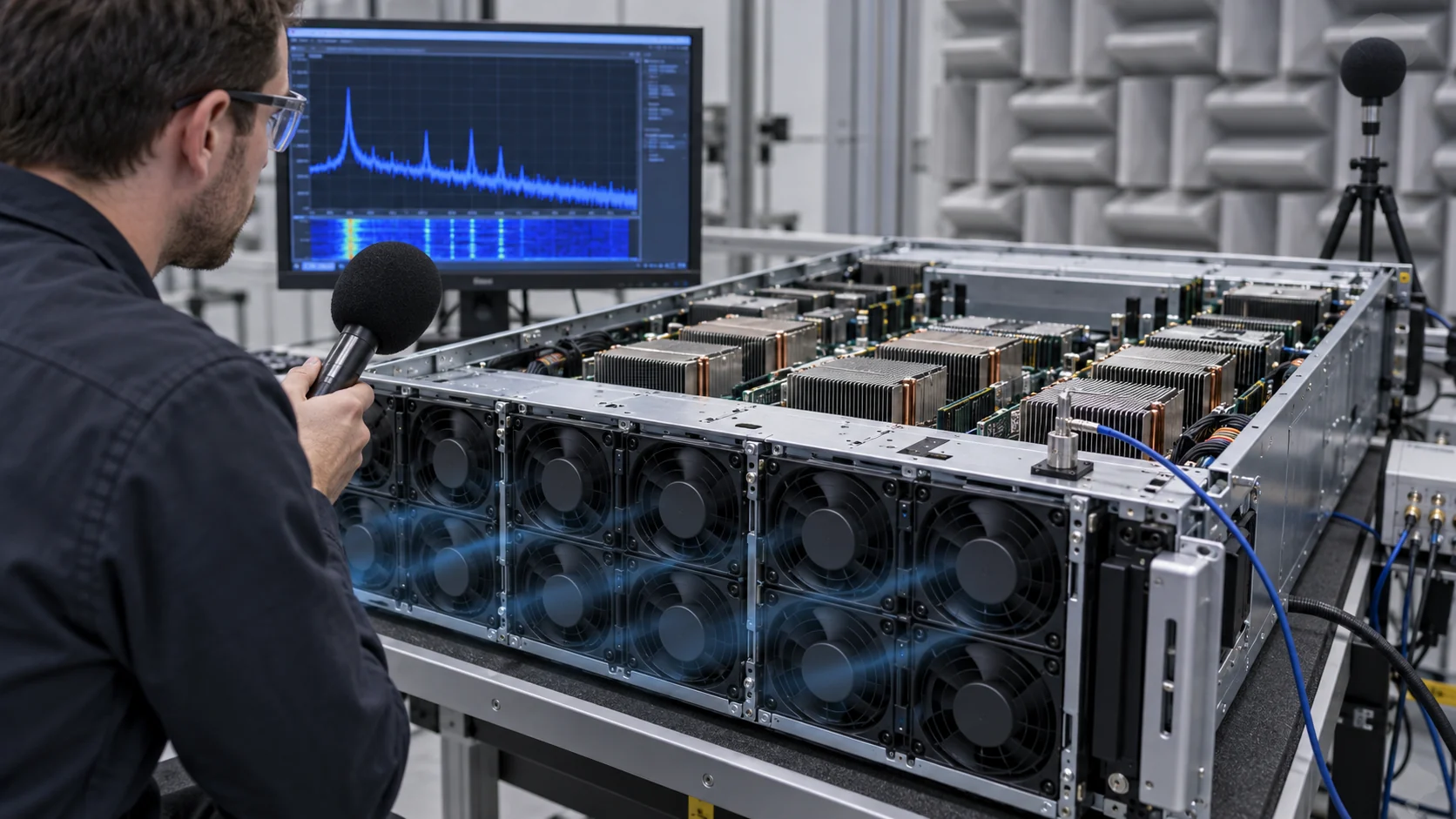
When Airflow Passes but the Server Still Sounds Wrong
A replacement fan can meet airflow and pressure targets yet create a sharp tonal peak that makes the whole server sound louder and less acceptable.
Server fan noise is often discussed as one A-weighted number. That number is useful for a specification, but it can hide the reason a new fan is rejected in a data-center room. Broadband airflow noise may rise gradually with speed, while a discrete blade-pass tone can appear as a narrow peak that the ear notices immediately. The peak can be created or amplified by a grille, an inlet obstruction, a short transition, a tray panel or a structural resonance.
The installed point matters. ASHRAE fan guidance notes that fan sound changes with operating point and that blade-pass frequency is linked to rotor speed and blade count. ISO 7779 provides a comparable way to measure IT equipment noise and includes methods for prominent discrete tones. A catalogue sound value from an open test rig cannot prove the result inside an AI server tray with the final heat sinks, cables and air duct. The same caution applies to supplier comparison: one vendor may report sound pressure at one metre in a free field, while another reports sound power for a complete functional unit. Convert neither value casually; align the test method before deciding which sample is quieter.
The engineering goal is not simply to make the fan slower. It is to keep the required thermal margin while avoiding a control range and mechanical geometry that amplify tonal noise. This article shows how to calculate the first blade-pass frequency, identify the source with a controlled test, and turn the result into a custom fan and PWM specification. The result should be a repeatable design rule: the server remains thermally safe, acoustically acceptable and serviceable at the installed working point.
Blade-Pass Frequency: The First Calculation
The first screening step is simple: relate RPM and blade count to the frequency that may appear as a tone.
The fundamental blade-pass frequency is fBP = RPM x blade count / 60. A seven-blade rotor at 12,000 RPM therefore produces a fundamental near 1,400 Hz. Its harmonics can occur near 2,800 Hz, 4,200 Hz and higher. A different blade count or a small change in speed moves the tone. That movement is useful during diagnosis: if the spectral peak tracks RPM, the fan or its aerodynamic interaction is a strong suspect.
The calculation does not predict loudness by itself. Loudness depends on loading, turbulence, blade geometry, inlet distortion, grille spacing, motor commutation, mounting and room transfer. A tonal peak can be small in a free-air test and prominent after a perforated panel reflects or reinforces it. The same frequency can also excite a tray panel or a rack door, making the measured sound appear to come from a large surface rather than from the rotor.
Record both the spectrum and the RPM. A time trace with only dBA cannot distinguish a broad rise from a narrow peak. Use a fixed microphone position, stable workload and repeatable fan command. Then sweep the speed in small steps and look for a peak that moves with the rotor. If the peak stays fixed while RPM changes, investigate a structural or electrical source instead.
| Blade count | RPM | Fundamental fBP | What to inspect |
|---|---|---|---|
| 7 blades | 9,000 | 1,050 Hz | Lower-speed operating band and inlet turbulence |
| 7 blades | 12,000 | 1,400 Hz | Tray or grille resonance near the moving tone |
| 7 blades | 15,000 | 1,750 Hz | High-duty acoustic and bearing-life penalty |
| 9 blades | 12,000 | 1,800 Hz | Different tone placement and harmonic spacing |
Animated Model: A Narrow Peak Can Move with RPM
The moving particles and spectrum marker show how a blade-pass tone can become stronger when the fan inlet is distorted by a nearby obstruction.
In the balanced panel, the fan receives a relatively even inlet and the spectrum is dominated by a broad low-level floor. In the distorted panel, a cable loop or grille close to the inlet creates nonuniform velocity. The rotating blades repeatedly encounter that pattern, so energy appears at the blade-pass frequency and its harmonics. The animation is intentionally qualitative; it does not claim a universal dB increase.
Use the model as a test prompt. Move the obstruction, change the fan speed and add or remove the tray panel while keeping the electrical command documented. If the peak changes with the geometry, the correction may be an inlet transition, a larger clearance, a flow straightener, a different blade design or a revised mounting interface rather than a lower nominal CFM fan.

The Operating Point Changes the Acoustic Trade-Off
The quietest fan at free air is not necessarily the quietest fan at the server's pressure and airflow duty.
A fan operating far to the left of its stable region can generate low-frequency turbulence and unstable flow. Operating far to the right can demand high volume flow, high velocity and higher broadband noise. The practical acoustic target is a stable installed point with enough pressure margin and a reasonable efficiency region. That point must include the heat sink, grille, filter, cable path and exhaust transition.
For example, a fan may produce 40 CFM in an open test at 35 dBA, but only 28 CFM at the chassis pressure needed by the GPU heat sink. If the controller raises speed until 40 CFM is recovered, the actual sound may be 49 dBA and the blade-pass peak may become dominant. A second fan with a better pressure curve could deliver the same useful flow at a lower speed even if its free-air headline is smaller.
Keep thermal and acoustic measurements synchronized. Record fan speed, PWM duty, current, static pressure, useful airflow, component temperature and spectrum for each test point. This lets the design team see whether a quieter state actually removes thermal margin or whether the current fan is simply operating in the wrong part of its curve. Add the pressure and airflow measurement plane to the report. A sound result measured with the grille removed is not a valid comparison with a sound result measured through the production grille, just as a free-air CFM value is not a chassis operating point.
In a multi-fan tray, also check phase and position effects. Two identical fans can create a stronger tone when their jets meet at a panel or when their blade-pass harmonics align at similar speed. A small speed offset may reduce a narrow peak, but it should not be used as a substitute for a stable thermal control strategy. If the design depends on speed staggering, document the allowed tolerance, start-up behaviour and the response after one fan changes duty or fails.
The acoustic acceptance should be written as a set of conditions rather than one number: maximum sound-power level, maximum prominent tone, maximum vibration at the tray, thermal pass condition and control response. This makes the result useful to the fan supplier, the chassis engineer and the data-center operator. Keep the same sample identity and firmware revision in every run, and archive the raw spectrum with the summary table for later comparison and future audits by the engineering team and purchasing team for release.
PWM Control Can Create or Remove a Tonal Problem
The controller determines how often the fan visits a noisy speed band and how sharply it enters that band.
A server controller commonly changes PWM duty as component temperature or inlet temperature changes. If the control curve crosses a structural resonance or a blade-pass frequency that is strongly amplified by the tray, the user may hear a narrow tone every time the workload changes. A small hysteresis band can prevent repeated movement around that speed. A controlled ramp can reduce the audible step, but it cannot fix a persistent resonance at the final operating point.
Check the PWM carrier and the motor's electrical behaviour separately from the aerodynamic tone. A low carrier or poor commutation can create audible electrical components, while an ultrasonic carrier does not remove blade-pass noise. Use an oscilloscope to confirm the command and FG signal, then use a microphone spectrum to identify the acoustic response. Do not label every tone as PWM noise.
Test the lowest stable duty, the normal duty, the degraded duty and the maximum permitted duty. At each point, hold the workload long enough for temperature to settle and record whether the tone is steady, intermittent or modulated. The final control table should specify the thermal reason for each speed band and the acoustic reason for any avoided band. Add a rate limit for speed changes when the workload step is known to be short, and define what happens if the controller must skip a noisy band during a fan fault. A control policy that is quiet only in normal operation but jumps directly to a resonant emergency speed has not been acoustically validated.
Structure, Mounting and Inlet Clearance Are Part of the Fan
A quiet rotor can become a loud assembly when vibration and airflow are transferred into the tray or chassis.
Fan vibration can reach a tray through rigid screws, compressed grommets, an uneven frame or a thin panel with a nearby natural frequency. The structure can radiate sound farther than the fan itself. OCP guidance for fan trays includes damping interfaces, vibration isolation and attention to the vent guard. Those details are not cosmetic: they change both the mechanical response and the inlet turbulence.
Keep a clear and repeatable inlet path. A cable crossing the rotor plane, a sharp edge close to the hub or a grille with an uneven open area can create nonuniform inflow. The closer the obstruction, the less opportunity the flow has to redistribute before entering the blades. If the fan must be close-coupled to a heat sink or panel, test the exact clearance and orientation rather than transferring an open-bench acoustic number.
Use an accelerometer or contact microphone on the tray when a tone is suspected to be structural. If the panel response rises at the same speed as the acoustic peak, compare a damped mounting interface, a stiffened panel and a revised clearance. The best solution may reduce vibration without changing the fan curve, or reduce inlet distortion without adding a heavier motor. Measure the response on the fan frame, tray rail, panel and chassis cover so the transmission path is visible. A remote microphone alone can show that the room is loud but cannot prove which part is radiating.
Check the mechanical interface after repeated service cycles. A grommet that is correct on the first installation can be over-compressed, torn or displaced after several fan-tray removals. The resulting hard contact can add a tonal vibration path even when the rotor itself is unchanged. The acceptance build should therefore include the approved fastener torque, gasket compression, service cycle count and the final cable restraint. These details are low-cost to document and high-value when a production acoustic complaint appears months later.
A Repeatable Acoustic Validation Procedure
The most useful test is a controlled matrix that changes one cause at a time.
Freeze the final hardware: fan tray, grille, heat sinks, cables, blanking panels, door, rack position and power limit. Establish background noise and the microphone or sound-power test method. Record the supply voltage at the fan, PWM, FG speed, current, pressure and airflow. If the project uses ISO 7779, follow the applicable installation and reporting conditions; otherwise document the internal method so samples are comparable.
Run a speed sweep with the same thermal load. At each point, capture a spectrum and note the blade-pass prediction from RPM and blade count. Then change one geometry variable: remove the inlet obstruction, add the production panel, move the cable, alter the clearance or change the mount. Finally repeat the thermal test at the speed bands that were acoustically suspicious.
A pass result should include the highest thermal load, the hottest inlet condition, the required airflow and pressure, the maximum sound-power or sound-pressure value, the limit for prominent tones, and the allowed transient during a workload step. A single quiet idle measurement is not enough for an AI server that spends most of its time changing power state.
Use a diagnostic matrix rather than changing several variables at once. If the tone follows RPM but not the tray position, inspect blade count, rotor balance and motor commutation. If it follows the tray position, inspect the local grille, panel and mounting. If it appears only with the production cable harness, inspect inlet distortion and clearance. If the acoustic peak remains fixed while RPM changes, inspect a structural mode, power electronics or a test-room reflection. This matrix keeps the sample iteration focused and prevents a fan supplier from being asked to solve a chassis resonance with a new motor.
For a practical example, assume an eight-fan tray has a broad level of 46 dBA at 11,000 RPM and a narrow 1.28 kHz peak. With an eight-blade rotor, the calculated blade-pass frequency is 1,467 Hz, so the measured peak is not a direct match and should not immediately be labelled blade-pass noise. When the speed is raised to 12,000 RPM, the peak stays near 1.28 kHz while the broadband floor rises. That result points toward a fixed panel or electrical resonance. If the peak instead moves from 1.28 to 1.47 kHz in proportion to RPM, the rotor interaction becomes the leading hypothesis. The numbers are illustrative, but the method is reusable.
Finally, repeat the test after thermal soak and after a controlled workload step. A warmed tray can change the stiffness of damping interfaces and the fan can move to a higher pressure point as component temperature rises. A short acoustic test at room temperature may miss the exact condition that operators hear during a sustained AI job.
- Measure at the final installed operating point, not free air only.
- Record RPM with every spectrum so blade-pass peaks can be identified.
- Separate broadband level, discrete tone and structural vibration.
- Test the cable, grille, heat sink and tray panel in their production positions.
- Repeat the acoustic check after thermal soak and workload step changes.
How MEGA Tech Helps Tune a Custom Server Fan
We connect the acoustic target to the installed pressure, control interface and sample validation rather than treating noise as an isolated catalogue value.
MEGA Tech develops custom DC axial fans, compact blowers and backward-curved centrifugal options for equipment airflow paths. We can review the operating point, frame and thickness, inlet and outlet geometry, PWM schedule, FG/RD feedback, voltage tolerance, connector, thermal load, noise limit, vibration concern and life assumption. The sample is evaluated against the customer's final tray or chassis rather than only against an open test fixture.
Please provide the airflow and static pressure at that airflow, the normal and degraded duty, the fan speed range, blade or rotor information if known, the microphone method, the problematic frequency or sound clip, the final grille and cable arrangement, the voltage tolerance, the quantity and the required life. If the issue is a replacement, include the original fan part number and the measured installed result. This lets the engineering team distinguish curve mismatch from resonance or inlet distortion.
Our boundary is precise: we do not provide the server chassis, BMC firmware, heat sink, rack acoustics or the customer's compliance certification. We support the fan and supplied air path, sample iterations and production alignment. The goal is a fan that meets thermal performance and acoustic requirements at the real working point, not a promise based on the outline size alone.
Engineer FAQ: Server Fan Tone and Vibration
Short answers for an acoustic and thermal design review.
Q: Why can a new fan be louder at the same RPM? A: Blade count, blade geometry, inlet distortion, grille interaction, motor commutation and structural coupling can change the spectrum even when speed is equal.
Q: How do I calculate blade-pass frequency? A: Multiply RPM by blade count and divide by 60. Then compare the predicted frequency and harmonics with the measured spectrum.
Q: Is a lower dBA number always better? A: Not by itself. Keep the spectrum and check prominent discrete tones, because a narrow peak can be more objectionable than a slightly higher broadband level. Also keep the test distance, room condition, airflow duty and background correction with the result so later samples are compared on the same basis.
Q: Can a PWM carrier create the blade-pass tone? A: PWM and blade-pass are different mechanisms. Confirm the electrical waveform and compare the acoustic peak with RPM before assigning the cause.
Q: What should a custom fan supplier receive? A: Send airflow and static pressure at the installed point, PWM and FG/RD details, voltage, frame, grille, cable path, sound limit, problematic frequency, quantity, environment and life assumption. Add the microphone position, spectrum file, measured RPM, heat-load state and whether the tone follows the fan, tray position or workload. That information makes it possible to select a sample for the actual acoustic mechanism instead of guessing from dBA alone. Include the final mounting interface and the pass/fail limit before sample approval, so an acoustic improvement is not purchased at the cost of thermal margin.
Questions for the Design Review
Use this checklist before releasing a server fan tray or accepting a replacement sample.
- Does the measured tone track RPM and the calculated blade-pass frequency?
- Has the final inlet obstruction, grille, cable path, heat sink and tray panel been installed during testing?
- Is the fan operating near a stable and efficient point at the required airflow and pressure?
- Does the controller repeatedly cross a resonant or objectionable speed band during workload changes?
- Are sound power, sound pressure, spectrum and vibration measured with a documented method?
- Can mounting damping or inlet clearance reduce the problem before changing the fan motor?
- Were the lowest voltage, highest inlet temperature and degraded fan state included?
- What exact data will be sent for a custom sample and what constitutes a pass?