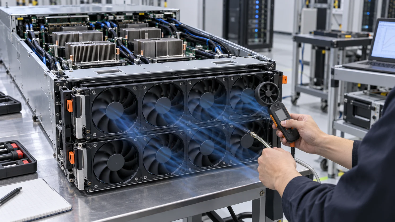
A Fan Tray Can Deliver the Right Total Flow and Still Create a Hotspot
The number on the airflow meter is not enough when one heat sink receives less air than its neighbours.
AI servers often use several fans in a row or a removable fan tray to feed GPUs, memory, networking, storage and power electronics. The arrangement looks symmetrical, but the air path rarely is. A cable bundle can narrow one inlet, a heat sink can have a higher fin pressure drop, a grille can sit closer to one rotor, and a transition panel can turn one fan's jet into another component. The result is fan-to-fan airflow mismatch even when every fan reports the same RPM.
A total chassis flow measurement can hide that mismatch. Suppose six fans deliver 1,800 CFM as a group. If the six channels receive 340, 320, 300, 290, 280 and 270 CFM, the average may look healthy while the last heat sink is operating with 20% less flow than the first. The worst component, not the tray average, controls the thermal margin. Increasing all fan speed may raise the total number while also increasing power and noise without fixing the restrictive channel. The imbalance can remain hidden during a short acceptance test.
The design-review question is therefore distribution: how much useful flow reaches each heat load, at what local pressure and at what fan duty? This guide gives a practical measurement method and shows where a custom fan sample, a shroud change or a balancing plate can create more value than another RPM increase. It also protects the purchasing decision. A low-cost fan that requires every channel to run at maximum speed may have a higher system cost than a better-matched fan with a stable mid-curve operating point, because energy, acoustic and bearing-life penalties accumulate across every server in the fleet.
What Engineers Mean by Airflow Uniformity
Define the metric before changing the hardware; different teams can use the same word for different measurements.
For a server fan tray, airflow uniformity can mean uniformity between fan channels, between heat sinks, across a fin stack, or across the front face of a rack. These are not interchangeable. The fan channel is the air moved by one rotor or module. The heat-sink flow is the fraction that actually crosses the thermal load. The face distribution is the spatial map measured with a grid or anemometer. A good report states which one is being discussed.
A simple channel-uniformity index is the minimum useful flow divided by the mean useful flow. In the example above, the minimum is 270 CFM and the mean is 300 CFM, so the index is 0.90. Another common report is the coefficient of variation, the standard deviation divided by the mean. Both are useful, but neither should be treated as a universal pass limit. The right limit depends on component sensitivity, thermal spreading and the control margin available to the hottest channel.
For a first design screen, report minimum, maximum, mean and range, then overlay the temperatures of the components served by each channel. If the lowest-flow channel is not the hottest, the heat load or heat-sink resistance may dominate. If the hottest component and the lowest useful flow coincide, the distribution problem is likely a high-value target for redesign. Repeat the map at two fan commands and one elevated inlet condition. A true path restriction usually remains visible as duty changes, while a sensor or workload artifact may change its ranking.
| Quantity | What it tells you | Typical limitation |
|---|---|---|
| Total chassis flow | Overall air moved by the tray | Can hide a starved heat sink |
| Fan-channel flow | Relative output of each module | Probe placement and jet swirl affect the reading |
| Local static pressure | Available pressure at a restriction | Meaning depends on the reference plane |
| Heat-sink flow proxy | Air crossing the actual thermal load | Often needs a calibrated hood, nozzle or thermal correlation |
| Component temperature | Actual thermal consequence | Sensor location and workload affect the result |
Animated Model: Equal RPM Does Not Mean Equal Useful Airflow
The moving particles compare a balanced tray with a tray in which one channel has extra resistance and another channel becomes a low-resistance shortcut.
The balanced panel shows three fans feeding three comparable heat-sink paths. The mismatch panel keeps the fan command visually similar but adds a cable restriction to the middle path and an open gap around the right path. The middle heat sink receives less useful flow while the right path carries air that does not cross the intended load. A tachometer on each fan can still show a normal speed. This is why a replacement specification should include a position-by-position pressure or airflow check, especially when the tray is short, the fans are close to one another, or the discharge immediately enters a fin stack.
The animation is not a CFD result and does not assign a universal percentage to cable blockage or leakage. Its purpose is to make the test plan visible: measure at the channel, at the restriction and at the component inlet. If the path changes after the final cable harness or blanking panel is installed, the fan sample must be evaluated in that final configuration.

Why the Weakest Channel Controls the Thermal Design
Averages help with capacity planning; the minimum useful flow protects the hottest component.
Consider four AI accelerator heat sinks with a target of 260 CFM each. A tray test records 290, 275, 265 and 225 CFM. The mean is 263.75 CFM, which appears to satisfy the target, but the fourth channel misses by 35 CFM. If that channel also serves the highest-power GPU, the average hides the design failure. The correct response is not to claim that the tray is within 1.5% of the average target; it is to find why the fourth path has the largest resistance or the smallest pressure margin.
The local temperature response provides a second check. If the fourth heat sink is 6°C hotter at the same workload, compare its inlet temperature, fin pressure drop, thermal interface and sensor position before assigning the entire difference to airflow. A useful experiment is to swap the fan module positions without changing the heat sinks. If the low flow follows the fan module, suspect the fan or its mounting. If it stays with the channel, suspect the system path.
This swap test is especially valuable for a replacement fan project. It separates fan-to-fan variation from geometry-to-geometry variation and prevents a supplier from being asked to compensate for a cable bend or an uneven shroud with an unnecessarily aggressive motor.
Measure the Installed Path, Not an Open-Bench Fan
The same fan can look balanced on a bench and become unbalanced after the final grille, harness and heat sinks are installed.
Start with the final mechanical stack: fan guard, tray frame, grille, filter or mesh, cable harness, blanking panels, duct transition, heat sink and exhaust restriction. Record the ambient condition and the supply voltage at the fan connector. Measure each fan's PWM command, FG speed, current and local pressure. Where a direct flow measurement is not practical, use a repeatable flow hood, calibrated nozzle, tracer grid or thermal proxy and state its uncertainty.
Make the measurement map part of the drawing. Mark the fan center, the pressure tap, the flow-grid points, the heat-sink inlet and the temperature sensor position for every channel. Repeat the same map after changing the fan, harness or shroud. This prevents a common failure in supplier comparisons: one sample is measured at the fan face while another is judged by a component temperature, so the team thinks it is comparing airflow when it is actually comparing different measurement planes.
Keep the reference plane fixed. A pressure tap immediately behind a rotor is not equivalent to a tap at the heat-sink inlet. The first may be dominated by jet momentum and swirl; the second includes the losses in the transition. Take enough points to identify the pressure gradient across the tray. If the middle fan sees a different upstream pressure because of an elbow or a cable loop, equal PWM is not equal operating point.
ASHRAE's modeling guidance is a useful discipline even for a small chassis: calibrate the model or design assumption against measured inlet temperatures and measured flow rates. You do not need a full data-center CFD model to apply the principle. The hardware decision should be tied to measurements that can be repeated on the final assembly. If a CFD model predicts a uniform fan face but the measured flow grid is uneven, do not average away the discrepancy. Check the boundary condition, fan location, grille pressure drop and the representation of the heat sink. A calibrated simple model is more valuable than an impressive uncalibrated color plot.
Separate Fan Variation from Path Variation
A controlled swap matrix can reveal whether the problem belongs to the motor, the fan position or the heat load.
Use at least two known-good fan modules and rotate them through the tray positions. Keep the command and supply voltage constant, then repeat the flow and temperature measurements. If the same module is always low, inspect its curve, bearing condition, connector and mounting seal. If every module is low in one position, inspect the inlet and outlet geometry at that position. If the flow is normal but the temperature is high, review the heat-sink contact and component power.
A second useful experiment changes only the obstruction. Run the tray with the production harness, then with the harness temporarily routed to the approved service position. The difference estimates the cost of the cable path. Do not use the open bench result as the acceptance number; use it as a diagnostic baseline. Repeat the comparison with the service door, blanking panels and nearby trays installed. Air can enter from a neighbouring opening during a bench test and make a restrictive channel look healthier than it will be in the rack.
For production, specify the measurement tolerance and the allowed fan-to-fan variation. A supplier can control electrical and aerodynamic variation, but the system owner must define how much distribution error the heat loads can tolerate. This prevents the vague requirement 'all fans must be equal' from becoming an impossible or meaningless purchase condition. It is also useful to define the sampling plan: test several positions, repeat the measurement after a thermal soak, and report the worst channel rather than selecting the most favourable reading. Procurement can then compare suppliers on the same evidence instead of comparing unrelated free-air figures. Include an acceptance rule for drift after burn-in and for the minimum FG signal at the lowest approved duty. A tray can begin balanced and become non-uniform after bearing friction, connector resistance or dust loading changes one channel's operating point.
Control Strategy: Balance the Load Before Adding RPM
A single tray-wide PWM command is simple, but it can waste power if one channel needs correction and the others do not.
If the hardware supports independent fan control, use the hottest or least-satisfied channel as a control input and confirm that raising its duty improves useful flow rather than leakage. If the fans share one command, mechanical balancing may be more effective: a short diffuser, a local seal, a larger radius bend, a flow straightener or a revised fan spacing can reduce the spread without increasing every fan's power.
Avoid using temperature alone to balance a tray when the sensor is slow or the workload changes quickly. Pair the thermal signal with fan feedback and a pressure or airflow proxy. Add hysteresis so the controller does not chase small sensor differences. A fan that repeatedly hunts between two commands can create more tonal noise and less predictable margin than a steady command with a small reserve. For a fleet design, review the control loop at both the fastest workload step and the slowest sensor update. A channel that responds too quickly can oscillate against a slow temperature sensor; a channel that responds too slowly can allow a short GPU power step to consume the available margin. The commissioning record should show both response time and final balance.
When the fan supplier is involved, provide the control curve and the minimum duty at which the motor remains stable. The sample should be evaluated at the actual duty schedule, not just at 100% PWM. Start-up, low-duty commutation, FG pulse interpretation and RD alarm behaviour can all affect channel balance.
Worked Example: A Small Balance Change Beats a Large RPM Increase
A simplified estimate shows how much power can be wasted by raising every fan to rescue one restrictive channel.
Assume a four-fan tray delivers 1,200 CFM at 40 W total and serves four equal heat loads. Measurements show 330, 315, 300 and 255 CFM, so the fourth channel is 45 CFM below the 300 CFM design target. The first test raises all fans by 10% speed. The group flow increases to 1,310 CFM, but the fourth channel reaches only 275 CFM while electrical power rises to an estimated 53 W. The weakest path still fails and the tray spends 13 W more.
A second test seals a 4 mm bypass gap and moves a cable bundle 12 mm away from the fourth inlet. At the original command, the measured distribution becomes 315, 307, 300 and 298 CFM. Total flow is nearly unchanged, but the minimum useful flow rises by 43 CFM and the spread narrows substantially. The estimate is illustrative, not a universal result; the point is that path resistance can dominate the improvement available from a global speed increase.
Use this type of comparison in a design review: report the baseline, the all-fan speed change, the mechanical balance change, the minimum channel, total power and the hottest component temperature. It makes the trade-off legible to both the thermal team and the purchasing team.
How to Select a Custom Fan for a Non-Uniform Tray
The correct fan is the one that gives the required useful flow at the installed pressure across the full control range.
Start with the worst channel and the normal channel as two operating points. If one fan must serve both positions, the P-Q curve should provide enough margin at the restrictive channel without forcing the low-resistance channel into excessive speed, noise or power. If independent control is possible, specify the normal and maximum duty for each position and confirm that the fan remains stable at the lowest command.
Provide the fan supplier with the frame and thickness, voltage tolerance, PWM frequency, FG or RD requirement, connector, inlet and outlet restrictions, airflow and static pressure at that airflow, noise target, environment, service life and quantity. Include the measured fan-position spread and the final shroud. A part-number comparison without the installed path can incorrectly reject a good sample or approve a poor one. If the tray is intended for a drop-in replacement, also provide the connector pinout, start-up sequence, alarm debounce, mounting gasket and the service position in which the fan is measured. Those details often explain a mismatch that cannot be solved by changing the impeller alone.
MEGA Tech can develop custom DC axial fans, compact blowers and backward-curved centrifugal options for the supplied air path. We compare the candidate at the customer's working point, support sample iterations and review the final tray or chassis. The objective is not to claim that one catalogue fan is universally equivalent to another; it is to produce a sample whose airflow, pressure, control and reliability are demonstrated in the customer's assembly.
Engineer FAQ: Fan-Tray Airflow Distribution
Questions that commonly decide whether a fan tray passes a final thermal design review.
Q: If all fans show the same RPM, can I assume the airflow is equal? A: No. Different inlet pressure, outlet resistance, mounting leakage and heat-sink paths move fans to different operating points even at similar speed.
Q: Is total CFM a valid acceptance metric? A: It is useful for system capacity, but pair it with minimum useful channel flow, local pressure and component temperature so a weak channel cannot hide behind the average. Include the measurement uncertainty and the final installed resistance in the record.
Q: Should I increase RPM when one heat sink is hot? A: First check heat load, sensor location, thermal interface, cable restriction, bypass and local pressure. A global RPM increase can waste power and increase noise without fixing the path. Confirm the weak channel at more than one duty point before changing the fan selection or releasing production hardware.
Q: How do I identify a bad fan versus a bad position? A: Rotate known-good modules through the positions. If the low result follows the module, inspect the fan. If it stays with the position, inspect the chassis path in production.
Q: What data should a custom fan supplier receive? A: The installed airflow and pressure points, fan envelope, voltage, PWM, FG/RD, connector, noise, life, environment, quantity and the final tray restrictions. Add the allowed fan-position variation, the weakest heat-sink channel, the maximum inlet temperature, the required transient response and the test method used to measure useful flow. That package lets the supplier propose a curve and sample that can be checked against the same evidence during the next design iteration.
Questions for the Design Review
Use this checklist before releasing a multi-fan AI server tray.
- What is the minimum useful airflow at each heat sink, not only the total tray airflow?
- Which channel has the highest resistance, and has that path been measured with the final harness and grille installed?
- Does the lowest-flow channel serve the highest-power component or the smallest thermal margin?
- Can fan modules be swapped between positions to separate fan variation from geometry variation?
- What are the pressure reference planes, probe uncertainty and flow-measurement repeatability?
- Does independent PWM control improve the weakest channel without creating noise or hunting elsewhere?
- What are the normal, low-duty, maximum-duty and high-inlet-temperature operating points?
- What exact P-Q curve and interface information will be sent for the custom sample?