N+1 Is a Topology, Not Proof of Safe Service
A server can contain one spare fan position and still overheat during a replacement if the airflow path, control loop and remaining fan curve are not validated together.
N+1 is often written into a server requirement as if it were a complete thermal argument: if one module stops, the other modules continue running. In a high-density AI server, that statement is only the beginning. Removing a fan changes the open area, the pressure distribution, the reverse-flow path and the command sent by the BMC. A remaining fan may have to operate at a higher point on its P-Q curve, while the empty bay may allow hot exhaust to recirculate through the chassis.
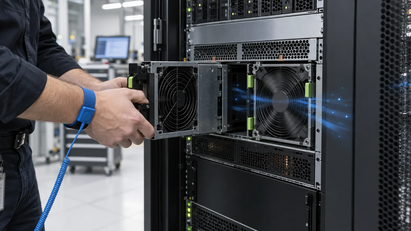
The service event is also transient. The system may be safe after the controller settles at a higher speed, but the hottest GPU, memory bank or power-stage heat sink can cross its limit before that new operating point is reached. The acceptance question is therefore time-based: how long can the module be absent, at what workload, with what inlet temperature and with what temperature margin? A short service interval also has to include the technician's real sequence: unlatch, pull, inspect, align, insert, latch and wait for feedback. Measuring only the time between electrical disconnect and reconnection makes the window look safer than the actual maintenance task.
This article treats a hot-swap fan tray as a measurable airflow state. It separates the normal working point, the removal transient, the stabilized one-module-out point and the recovery after the replacement is inserted. The numbers below are engineering examples, not universal limits; the final window must be established on the actual chassis and workload.
Four States Must Be Tested, Not Just the Final State
A useful hot-swap test records the chassis before, during and after service so a passing steady-state result cannot hide a dangerous transient.
State one is normal operation: every fan is present, the inlet temperature is at the design value and the AI workload is producing the expected heat. Record fan command, tach feedback, current, chassis differential pressure, inlet temperature at the top and bottom of the rack, and the hottest component temperature. These values define the reference point for the remaining three states.
State two is the removal transient. Start the timer at the moment the fan electrical connection opens or the module leaves the airflow plane. Record the fastest thermal rise, the first controller response and the minimum airflow delivered through the load. A one-second sample may be needed for a short service window; a one-minute trend can miss the peak.
State three is the stabilized one-module-out condition. Wait until fan command, temperature and pressure have reached a repeatable plateau. State four is recovery: insert the replacement, confirm its direction and feedback, and verify that the BMC returns to the intended control band without hunting or overspeeding adjacent fans.
| State | What changes | Record before declaring pass |
|---|---|---|
| Normal | All modules installed | Inlet temperature, component temperature, airflow proxy, pressure, PWM, tach and current |
| Removal transient | One module disconnected or extracted | Time-to-limit, peak temperature slope, remaining-fan response and reverse-flow evidence |
| One-module-out | Bay empty and remaining fans at the new duty | Stable temperatures, useful airflow, pressure margin, noise and power |
| Recovery | Replacement inserted and enabled | Direction, FG/RD feedback, ramp stability, final operating point and alarm clear |
Animated Model: The Empty Bay Can Become a Short Circuit
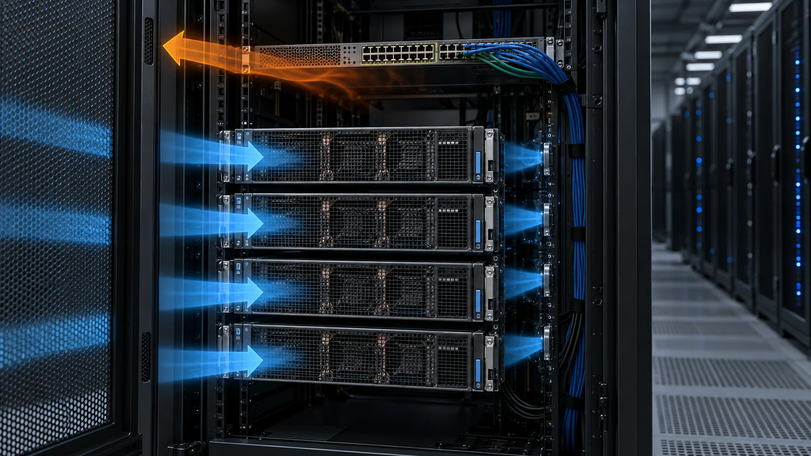
The moving particles show why a failed module is not automatically a blocked module; an open bay can redirect air around the heat load.
In the controlled panel, a louver, shutter or close-fitting service blank keeps the pressure boundary intact while the remaining fans carry the load. In the uncontrolled panel, the empty opening becomes a lower-resistance path. Some air moves from the hot side back toward the inlet, so the fan tachometer can look normal while the heat sink receives warmer air.
The figure is not a CFD result and does not assign a universal leakage percentage. It is a design-review prompt: remove the module in a controlled test, use smoke or a permitted tracer method, and measure the inlet temperature and pressure on both sides of the bay. If the empty bay changes the flow direction, the mechanical interface is part of the fan specification.

The Thermal Window Is Set by the Fastest-Rising Component
A chassis average can remain comfortable while one GPU memory region or power stage reaches its protection threshold.
Choose the component that has the shortest thermal time constant or the smallest allowable margin. In an AI server this may be a GPU hotspot, HBM or memory module, VRM inductor, optical transceiver, storage controller or a power-conversion heat sink. Place sensors where the component supplier allows, then correlate the sensor with the inlet and exhaust temperatures. Do not use only the rear exhaust temperature as the service criterion; it responds after the hottest local point has already changed.
A simple screening calculation is useful. Suppose the hottest component is at 82°C in normal operation, the validated limit is 95°C, and the one-module-out test produces a measured rise of 0.9°C/s for the first 5 seconds. The immediate thermal margin is 13°C, but the first five seconds consume 4.5°C before the control loop has settled. That leaves 8.5°C before considering sensor delay, workload variation and measurement uncertainty.
For a production requirement, define a pass condition such as: no component exceeds its validated limit, the maximum slope stays below the approved value, the fan controller reaches the degraded operating point within the service time, and the inlet-temperature rise at the hottest rack position remains within the system budget. The exact limits belong to the equipment owner, not the fan supplier alone.
Remaining Fans Move to a New P-Q Point
When one fan is removed, the parallel fan group and the chassis resistance must be evaluated again; the original free-air CFM does not describe the degraded state.
For fans operating in parallel, the available flow at a given pressure is the sum of the individual fan flows only when the fans share a compatible operating condition. Removing one fan changes both the group curve and the velocity distribution through the fan wall, grille, heat sink and cable obstruction. If the empty bay leaks, the effective system curve can also change in the opposite direction. A spreadsheet that simply subtracts one catalogue CFM cannot represent that interaction.
Use the installed resistance points that matter: fan guard, filter, inlet mesh, heat sink, board gap, exhaust grille, cable bundle and any louver. Measure or estimate the pressure at the fan plane and the airflow through the thermal load. Then compare normal and one-module-out curves. The desired result is not necessarily the same RPM; it is enough useful airflow at an acceptable noise, power and life cost.
A practical sample plan uses three command levels: normal duty, degraded duty and emergency duty. At each level, record total electrical power, each fan's command and feedback, the pressure differential and the temperature map. This makes a custom fan decision traceable: the sample is selected for the actual degraded point, not just its maximum airflow headline.
Do not treat the pressure measured at the fan inlet as the whole chassis pressure. A hot-swap tray can have a sharp local loss at the grille or a bypass around the heat sink. Measure the pressure before and after the restrictive assembly, and if possible use a calibrated flow nozzle or a repeatable thermal proxy. The purpose is to identify whether the missing module reduces total flow, redistributes flow, or mainly creates a reverse path. Each failure mode leads to a different mechanical or fan-control correction.
Control Transients: PWM, FG and RD Are Part of Thermal Safety
A mechanically adequate fan can still fail the service test if the control interface delays detection, commands the wrong ramp or loses feedback during insertion.
The BMC or fan controller should distinguish a removed module, a stalled rotor, a disconnected tach signal and a fan that is turning but delivering reduced airflow. FG feedback confirms rotation frequency, but it does not directly confirm useful airflow at the heat sink. RD or lock output can shorten detection of a stopped rotor, while an airflow proxy or temperature slope can expose a partially obstructed module.
During hot insertion, check the electrical ramp, start current, PWM duty, FG settling time and alarm debounce. A fan that starts too aggressively may produce a pressure shock and acoustic event; a fan that starts too slowly may leave the hottest component exposed. Test at the lowest permitted supply voltage and at the highest expected inlet temperature, because motor margin and bearing drag are not constant.
The acceptance record should retain the time series, not only a green alarm state. Include the command sent by the controller, the feedback returned by the fan, the measured current and the thermal response. This evidence is especially important when replacing a named fan with a custom sample: the electrical interface must match the system behaviour, not only the connector shape.
Also test a deliberately slow or missing feedback signal if the controller supports that diagnostic. Some systems wait for several tach periods before declaring a fault, while others raise an alarm as soon as the signal disappears. The thermal result can differ by many seconds. If a fan can rotate but its connector is loose, the BMC may see an intermittent FG signal and repeatedly change duty. That hunting behaviour should be captured because it can increase both temperature and acoustic stress even though no single alarm remains active for long.
Acoustic and Vibration Penalties Can Hide in the Recovery Ramp
A one-module-out event often pushes the remaining fans into a tonal region that is absent during normal operation.
After a fan is removed, the controller may increase all remaining fans to the same high command. That can create blade-pass tones, grille interaction or a structural resonance in the tray. The sound may be brief, but repeated maintenance events can reveal a design problem and a vibration impulse can disturb nearby connectors or storage devices. Record a narrowband spectrum at the normal, degraded and recovery states rather than relying on one dBA number.
Separate fan noise from chassis noise. Measure with the final grille, blanking panels, louver and cable routing installed. If one module position produces a noticeably stronger tone, check its clearance and mounting compliance before changing the motor. OCP specifications also call out vibration isolation for fan modules, which is a reminder that the frame, tray and fan must be treated as one assembly.
The most useful control strategy is often a controlled ramp with hysteresis: raise the remaining fans quickly enough to protect the load, but avoid repeated speed hunting when the replacement module is inserted. The validated result should include sound pressure, vibration and the time required to return to the normal speed band.
Worked Example: A Two-Minute Window Is Not a Design Constant
Vendor documentation may define a replacement interval, but the useful interval depends on the actual heat load, inlet condition and control response.
Consider a 4U AI server with six fan modules. At a 27°C inlet and a 6 kW workload, the hottest measured component is 78°C with all modules installed. The service requirement removes one module for 45 seconds. During the test, the remaining fans reach their degraded command after 3 seconds, but the hottest component rises to 86°C and then stabilizes at 88°C. At a 95°C validated limit, the final steady-state margin is 7°C and the transient consumes 8°C of the original margin.
Now repeat at 32°C inlet and a 7.2 kW workload. The same fan command produces less thermal margin, and the empty bay leaks hot air toward the inlet. If the component reaches 94°C at 28 seconds, the nominal 45-second service interval fails even though the lower-load test passed. The correct engineering response may be a louver, a shorter service interval, a different fan curve, a lower workload during service, or a revised mechanical path. It may also be a procedure change: temporarily cap GPU power, hold the workload at a defined state, or service only one chassis in a row at a time. Those controls should be written into the acceptance condition rather than left as informal technician knowledge.
The example is intentionally simple. It demonstrates why a replacement time printed in a service manual cannot be copied into a new AI platform without re-testing. The pass window must be tied to heat load, inlet temperature, fan control, component limit and the actual fan tray geometry.
A Commissioning Procedure Engineers Can Reuse
A repeatable record is more valuable than a single successful demonstration.
Before the test, freeze the hardware configuration: fan tray, grille, heat sinks, blanking panels, cable routing, firmware, sensor locations and power limit. Measure the normal P-Q point or a defensible airflow proxy at the final installed resistance. Confirm the fan direction and label every module position. Define the workload, inlet temperature, service tool and maximum allowed removal time.
During the test, log at a fast enough interval to catch the first thermal slope. Remove one module at a time, not several, unless the system requirement explicitly calls for a larger failure. Record pressure at the fan plane or chassis inlet, fan PWM, FG/RD, current, component temperatures, inlet temperatures and acoustic peaks. Repeat at the farthest or most restrictive airflow path, not only on a convenient bench unit.
After the test, restore the module and confirm that the system returns to the same normal operating point. Compare the pre-test and post-test fan current, speed, pressure and temperature. Keep the degraded-state curve, the thermal trace and the service timing with the design record. If the system fails, change one variable at a time so the next sample teaches the team what actually solved the problem.
Repeat the test after thermal soak rather than only from a cold start. Bearings, motor electronics and the chassis structure reach a different condition after sustained high load. A replacement that starts immediately on a cool bench may not restart with the same margin after the tray has operated at elevated temperature. The final report should state the soak duration, inlet temperature, workload power, firmware version, sample identity and measurement uncertainty so a later supplier change can be compared fairly. Include a second run after a controlled power step if the platform changes fan duty with GPU utilization; a steady thermal soak alone does not prove recovery from a workload transition.
- Pass the hottest component, not the average chassis temperature.
- Measure reverse or bypass flow at the empty bay instead of assuming the opening is neutral.
- Validate the lowest supply voltage and highest inlet temperature, not only nominal laboratory conditions.
- Keep the final grille, heat sink, blanking panel and cable path installed during the test.
- Record the recovery state after reinsertion and confirm feedback, direction and alarm clearing.
How MEGA Tech Supports a Custom Fan-Tray Sample
We help turn a degraded operating point into a measurable fan specification and a sample that can be tested on the customer's chassis.
MEGA Tech develops custom DC axial fans, compact blowers and backward-curved centrifugal options for equipment airflow paths. We review the installed working point rather than selecting by a catalogue CFM headline. For a fan tray, that includes normal and one-module-out resistance, the fan spacing, the grille and heat sink, the service opening, the required airflow direction, the acoustic target and the control response during insertion.
Please provide the airflow and static pressure at that airflow, inlet-temperature and altitude basis, voltage tolerance, PWM or analogue command, FG/RD requirements, connector, envelope, quantity, noise target, environment and life assumption. If the fan is a replacement, include the original part number plus the measured operating condition. We can use the customer's sample chassis and final mechanical restrictions to compare a custom sample against the real system curve.
Our boundary is important: we do not supply the data-center rack, BMC, heat sinks, cabinet safety procedure or the customer's service authorization. We validate the fan and the air path that the customer provides, then support sample iterations and production alignment. Same outline dimensions do not automatically mean equivalent cooling; the degraded operating point must be demonstrated.
The most useful first exchange is usually not a catalogue request. It is a short measurement package: a photo or drawing of the tray, the fan position and direction, the normal and degraded command, the pressure or airflow proxy, the hottest sensor trace and the service window. That information lets the engineering discussion start at the actual risk rather than at a maximum-CFM number for design review.
Engineer FAQ: AI Server Fan Hot-Swap Validation
Short answers to the questions that normally appear in a design review.
Q: Is N+1 enough to approve hot-swap service? A: No. N+1 defines a count relationship. Approve the actual transient and stabilized one-module-out thermal states at the specified workload and inlet condition.
Q: Should an empty fan bay be sealed? A: Usually the airflow path should be controlled, but the correct louver or shutter depends on pressure, service clearance and the fan tray. Test the installed geometry rather than assuming a solid blank is always best.
Q: Can FG feedback prove the server is cooled? A: No. FG indicates rotation frequency. It does not prove useful airflow through a heat sink, so pair it with pressure, airflow proxy and component temperature.
Q: Is a two-minute replacement window transferable between platforms? A: No. A published window is a system-specific example. Heat load, inlet temperature, fan curve, sensor delay and the empty-bay path can change the result.
Q: What should be sent to a custom fan supplier? A: Send the fan envelope, voltage, control and feedback interface, airflow and static pressure at that airflow, final resistance, noise target, service state, quantity, environment and life assumption.
Questions for the Design Review
Use this checklist before releasing a server fan tray or approving a replacement fan.
- What is the validated thermal limit and which component reaches it first during removal?
- What are the normal, transient, one-module-out and recovery operating points?
- Does the empty bay create reverse flow, bypass or hot-air recirculation at the inlet?
- What is the minimum supply voltage, maximum inlet temperature and highest workload for the test?
- How quickly does the controller detect removal, raise the remaining fans and clear the alarm after insertion?
- Has the final grille, heat sink, blanking panel, louver and cable routing been included in the test?
- What pressure, airflow proxy, component temperature, current, PWM, FG/RD and acoustic data will be retained?
- What exact P-Q point and interface information will be sent for a custom fan sample?