Liquid Cooling Does Not Mean Zero Airflow
Direct-to-chip cooling removes heat from the highest-power devices, but the rack still has air-cooled components that can set reliability, noise and fan requirements.
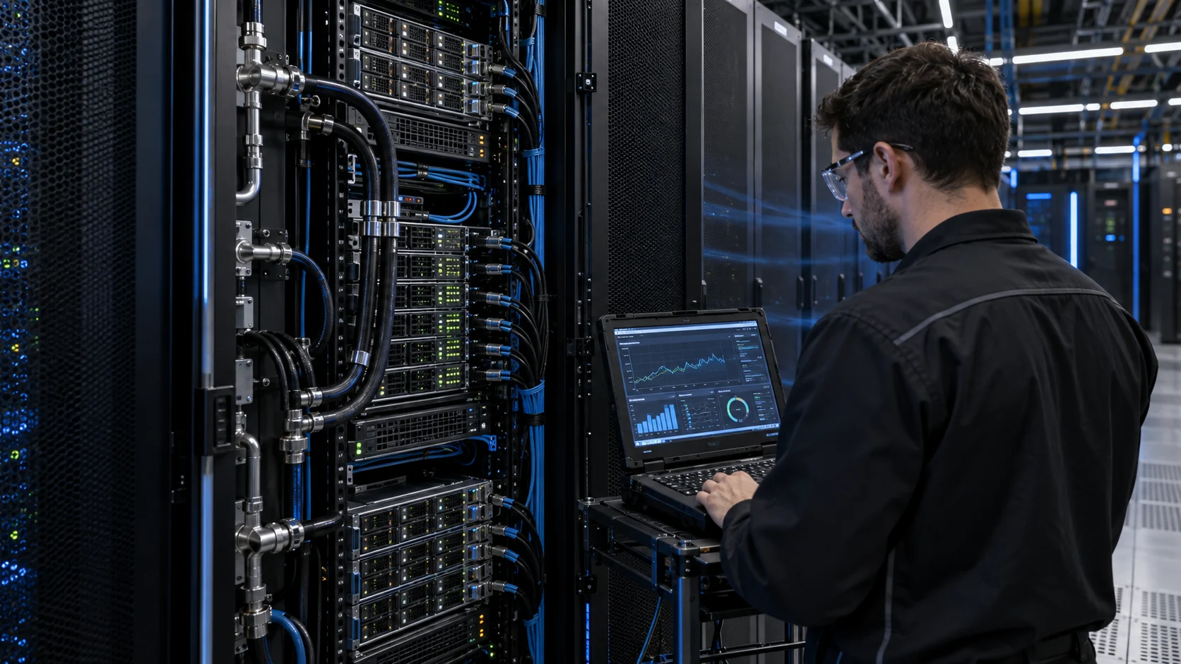
The phrase liquid-cooled AI rack is easy to misunderstand. Coolant may remove most GPU or CPU heat through cold plates, but power shelves, memory, storage, network switches, voltage regulators, management controllers and cable-side electronics may still reject heat to air. The coolant distribution unit can also transfer return-loop heat to room air in a liquid-to-air arrangement. The rack therefore becomes a hybrid thermal system, not a rack without fans.
ASHRAE describes liquid-cooled datacom equipment as one part of a broader system and notes that residual heat remains in air-cooled components. Its AI data-center framework recommends retaining facility air cooling for the residual 10–30% of heat from power supplies, memory, storage and networking. The exact percentage is architecture-specific, but the engineering consequence is general: measure the air-side load instead of assuming the liquid loop covers it.
This guide shows how to define an auxiliary fan working point for a liquid-cooled AI rack. It focuses on the air path around power shelves and network zones, CDU air-side heat rejection, filter and grille pressure, bypass, acoustic behavior, PWM and fault response. The numerical examples are engineering estimates for design discussion, not MEGA product ratings or a facility performance claim.
Map the Residual Heat by Rack Operating State
The air-side fan is selected from the components that remain air-cooled at the real AI workload, not from the total rack nameplate.
Create a heat map for at least idle, inference, training, power-shelf peak, network peak, CDU heat-rejection peak and maintenance-bypass states. List the heat entering the air path from each power shelf, memory bank, storage device, switch, BMC, fan controller and auxiliary converter. If the CDU is liquid-to-air, include the heat it rejects to the room or rack air at the relevant coolant flow and return temperature.
As an illustrative estimate, suppose a 72 kW liquid-cooled rack leaves 8% of its load to air through power shelves, network equipment and control electronics. The air-side load is 5.76 kW. If a separate CDU rejects 1.2 kW to the same air path, the total air-side load becomes about 6.96 kW. That does not mean one rack fan must remove the whole value; some heat may be captured by room airflow or a separate CDU fan wall. The point is to define the boundary before selecting the rack fan.
Split the heat budget by physical path. A power shelf inlet may need a high-static-pressure fan through a narrow filter, while a network switch may need a more open axial path. A CDU heat exchanger may have a different fan curve and control loop. Combining these paths without measuring them can create a cold power shelf and a hot network zone, or a high fan speed with little useful flow. Keep the accounting traceable: write down whether each watt is a component loss, a coolant-side load, an air-side load or a facility-side rejection load. The same heat must not be counted twice, but residual heat must not disappear simply because the rack is called liquid cooled.
| State | Record | Question |
|---|---|---|
| Idle / standby | power-shelf loss, network load, fan minimum duty | Does the fan run stably at low noise? |
| AI workload | GPU coolant state, memory/network temperature and air-side load | Which residual zone limits first? |
| Power peak | shelf current, inlet temperature and heat-sink temperature | Does the fan meet the shelf working point? |
| CDU air rejection | coolant flow, return temperature and air-side dP | Is CDU heat on the same air path? |
| Maintenance bypass | failed fan, blocked path and component temperature | Does the rack enter a controlled state? |
Calculate Airflow for the Air-Cooled Boundary
Use a heat balance for the air-side boundary, then verify the fan against the pressure curve and the real rack geometry.
For an air-side heat load, use Qv = P / (rho x cp x delta-T). If the defined boundary is 6.96 kW, air density is 1.15 kg/m3, heat capacity is 1005 J/(kg K), and the allowed air rise is 12 K, the ideal starting airflow is 6,960/(1.15 x 1005 x 12) = 0.500 m3/s, or about 1,800 m3/h. This is a heat-balance estimate before pressure loss, recirculation, redundancy and sensor margin.
Now measure the path. A power-shelf filter might contribute 85 Pa, a grille 42 Pa, cable and busbar blockage 55 Pa, a heat sink and guard 70 Pa, and the outlet or containment transition 48 Pa. The clean path is approximately 300 Pa. At service-limit filter pressure, the path may rise to 390 Pa. The fan selection must show the required airflow at both pressures.
Do not transfer the room fan-wall curve to the rack fan without checking the boundary. A rack-mounted fan may only cool the power and network zones, while a CDU fan rejects a separate load. Define where air enters, where it leaves and which heat sources are included. A clean diagram prevents double-counting heat and also prevents a thermal zone from being left without a real air path.
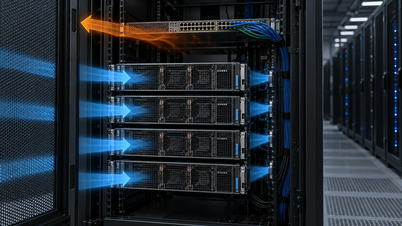
Animated Model: Liquid Path, Air Path and Bypass
The schematic separates coolant flow from useful air so the design review can see where a liquid-cooled rack still depends on fan performance.
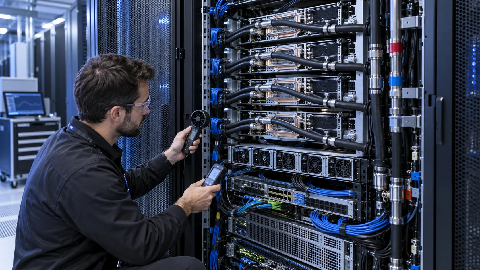
Use the figure to define three tests: normal AI workload with coolant at its design condition, power-shelf peak with the liquid loop stable, and a maintenance or failed-fan condition. Measure coolant supply and return temperature separately from rack inlet air, power-shelf heat-sink temperature, network-zone temperature and exhaust temperature. A cool GPU cold plate does not prove that the switch or power shelf is within its air-side limit.
Check for bypass around shelves, blanking panels, cable openings and the rack door. A liquid-cooled server can have a low air requirement while the remaining air path is still highly resistive because the rack was not designed as an ordinary open server rack. The animation is a qualitative model, not CFD, a pressure curve or a facility acceptance result.

Power Shelves and Network Zones Need Different Evidence
A single rack inlet temperature is not enough when power conversion and networking occupy different air paths.
Power shelves often have their own internal fans or a high-resistance inlet. Record shelf inlet, exhaust and heat-sink temperature, along with input current, output power and fan feedback. If the rack uses 48 V distribution, include conversion loss and connector heating where they enter the air boundary. Check whether a failed shelf fan increases the load on adjacent fans or creates reverse flow through an idle shelf.
Network switches and optical modules can be sensitive to local inlet temperature and blocked cable-side exhaust. Measure the hottest switch zone and the temperature near dense optical or copper connections. Cable bundles can close a nominal opening and create a pressure rise that is absent from the empty-rack drawing.
Use separate acceptance criteria for each zone. A rack may pass a total exhaust-temperature limit while a power shelf exceeds its local limit. Conversely, increasing all fans can solve a local temperature problem while creating unnecessary noise and energy use. The goal is balanced useful flow, not a maximum RPM headline.
CDU Air Rejection and Room Containment Are Part of the Fan Path
A liquid-to-air CDU can move heat from coolant into room air, linking the rack fan decision to the hot aisle, containment and return path.
A liquid-to-liquid CDU transfers heat between a technology loop and facility loop without putting facility water directly into the IT equipment. A liquid-to-air CDU rejects return coolant heat into air, so its fan and coil pressure become part of the air-side design. Schneider Electric's reference design shows liquid-cooled AI racks, networking racks, L2A CDUs and fan-wall cooling as a combined system rather than isolated products.
Measure CDU supply and return coolant temperatures, coolant flow, air inlet and outlet temperature, coil differential pressure and fan duty. If the CDU exhaust enters a hot aisle, confirm that the room return path can carry it without recirculating toward rack inlets. If the CDU is beside the rack, a wall, cable tray or containment curtain can change the operating point. Repeat the measurement with doors, containment curtains and adjacent racks in their normal positions; an open commissioning aisle is not the same system as the operating data hall.
Do not use the rack auxiliary fan to compensate for an undersized CDU air path. The fan supplier can help characterize a fan at the supplied coil or grille pressure, but the facility designer remains responsible for the loop, heat rejection capacity, containment and water-side safety. Keep a separate sign-off for air-side fan performance and liquid-side heat rejection so a successful fan test is not mistaken for approval of the complete cooling system.
Define the degraded cooling state explicitly. If coolant flow falls, the CDU pump trips or a leak sensor forces a controlled reduction in IT load, the auxiliary fan may still need to cool power shelves and networking while the rack transitions. Conversely, increasing rack airflow cannot replace the thermal capacity of a missing coolant flow. Record the sequence, timing, temperature limits and fan command in the protection analysis so the air-side sample is not asked to solve a liquid-side fault it cannot solve.
Fan Control, Redundancy and Reverse-Flow Checks
PWM and FG/RD can reduce auxiliary fan power, but a liquid-cooled rack still needs a defined response when air cooling is lost.
Drive auxiliary fans from the limiting air-cooled zone and use power or workload feed-forward where available. Add hysteresis and a minimum run time so the fan does not hunt as the AI workload changes. Record the minimum stable duty, startup boost, speed feedback and current at the lowest permitted supply voltage.
For an illustrative energy estimate, four 48 V fans drawing 0.16 A each consume 30.7 W at full input. If the fans average 45% input for 20 hours and full input for 4 hours during power and maintenance peaks, the idealized fan energy is 30.7 x (0.45 x 20 + 4) = 399 W h per day. This is not a PUE or energy-saving claim; it shows why a validated variable-speed curve matters when the rack operates continuously.
Test N+1 or N+2 assumptions rather than accepting them by name. When one fan stops, measure reverse flow through the idle fan, the remaining fan operating point, local temperatures and control response. A redundant fan can add resistance when stopped. The rack may need a backflow damper, a different fan curve or a control rule that increases the remaining fan duty.
Also check hot-swap and maintenance states. Removing a server tray, power shelf or network module can open a large temporary bypass and change the pressure seen by every remaining fan. A replacement tray can close that opening again. Measure before and after service, and make sure the control system does not learn a temporary open-door condition as its normal operating point. This is especially important when the rack is commissioned one shelf at a time.
An Anonymous Customer Scenario: Liquid-Cooled GPUs, Hot Network Shelf
An AI-infrastructure integrator found that the GPU cold plates were within their coolant target while a network shelf approached its air-side limit during a sustained workload.
The prototype rack used direct-to-chip cooling for the high-power compute modules and a low-speed auxiliary fan path across the power and network sections. The first thermal report focused on coolant supply and return temperature. During a long workload, however, the network shelf near the cable side warmed faster than expected. The rack exhaust looked acceptable because a bypass gap allowed some air to leave without crossing the shelf.
MEGA Tech reviewed the residual air-side heat budget, shelf inlet pressure, cable routing, blanking panels and fan feedback. A high-static-pressure axial sample and a compact centrifugal sample were compared at the installed path. The integrator also added a simple baffle and closed the cable-side bypass before judging the fan.
The revised validation record separated GPU coolant evidence from power-shelf and network-air evidence. It included clean and restricted-path pressure, local component temperature, fan command, FG/RD, acoustic result and the failed-fan state. The engineering decision was to use a pressure-matched auxiliary fan curve rather than increase all rack fans indiscriminately.
This is an anonymized engineering scenario, not a public customer performance claim. The transferable lesson is that a liquid loop can be healthy while an air-cooled rack subsystem still needs a carefully measured fan operating point.
| Test | Measurements | Decision |
|---|---|---|
| Normal workload | coolant temperatures, shelf/network temperatures and fan duty | confirm residual air-side margin |
| Power peak | shelf current, heat sink and local pressure | verify the highest air-side load |
| CDU air rejection | coil dP, air inlet/outlet and coolant flow | confirm the CDU boundary |
| Loaded or blocked path | filter/grille pressure, airflow and temperatures | define the service limit |
| Failed fan | reverse flow, remaining fan duty and alarm response | verify redundancy instead of assuming it |
How MEGA Tech Supports Hybrid AI-Rack Fan Selection
We help select the auxiliary DC fan from the residual air-side working point while keeping the liquid and facility boundaries clear.
MEGA Tech develops custom DC axial fans, compact blowers and backward-curved centrifugal options for power shelves, network compartments, BMC zones, rack service modules and air-side CDU interfaces. We review the installed P-Q point, filter and grille pressure, fan direction, PWM or voltage control, FG/RD feedback, connector, startup, reverse flow, acoustic target, vibration, bearing choice, environmental condition and quantity.
For a first review, provide the residual heat by zone, airflow and static pressure at that airflow, coolant and air operating temperatures, fan envelope, filter or grille data, minimum and maximum voltage, control and feedback interface, noise target, redundancy assumption, service condition and quantity. A rack section drawing with cable and busbar routing is more useful than a maximum-CFM request.
Our current published product data is focused on custom DC fan variants. We do not supply the CDU, coolant, cold plate, server motherboard, rack safety system or facility water loop. We can support the fan and supplied air path with samples and replacement options for Sanyo Denki, SUNON, Delta, NMB and ebm-papst, but same frame size does not automatically mean equivalent performance.
Engineer FAQ: Auxiliary Fans in Liquid-Cooled AI Racks
Short answers for a hybrid cooling design review.
Q: If the GPUs are liquid cooled, do I still need rack fans? A: Often yes. Power shelves, memory, storage, networking, controls and some CDU architectures remain air cooled.
Q: Can I size the auxiliary fan from total rack kW? A: No. Define the residual air-side heat boundary and the exact components included before calculating airflow.
Q: Does a healthy coolant loop prove the rack is thermally safe? A: No. Check local power-shelf and network temperatures, air pressure, useful flow and cable-side bypass, especially during sustained workload and service states.
Q: Is N+1 enough without reverse-flow testing? A: No. A stopped fan can add resistance or allow recirculation. Measure the remaining fan working point and the failed state.
Q: What should we send for a custom fan sample? A: Provide residual heat, airflow and static pressure at that airflow, voltage, control, feedback, envelope, filter pressure, acoustic target, redundancy and environment. Also send the rack section with cable routing and identify the liquid and air boundaries so the sample is evaluated against the correct path.
Questions for the Design Review
Use this checklist before releasing an auxiliary fan or hybrid liquid-air rack design.
- Which rack components remain air cooled, and what is their heat load at the AI workload?
- Is CDU air-side heat rejection included in the correct thermal boundary?
- What are the clean and service-limit pressure drops at the required airflow?
- Could cables, blanking panels or containment create a bypass around the limiting zone?
- Does the fan meet the working point at the highest inlet temperature and lowest voltage?
- What happens when one fan stops, and has reverse flow through the idle fan been measured?
- Are coolant, air-side and facility-side responsibilities clearly separated?
- What exact P-Q, rack-section, filter and control information will be sent for the sample?