
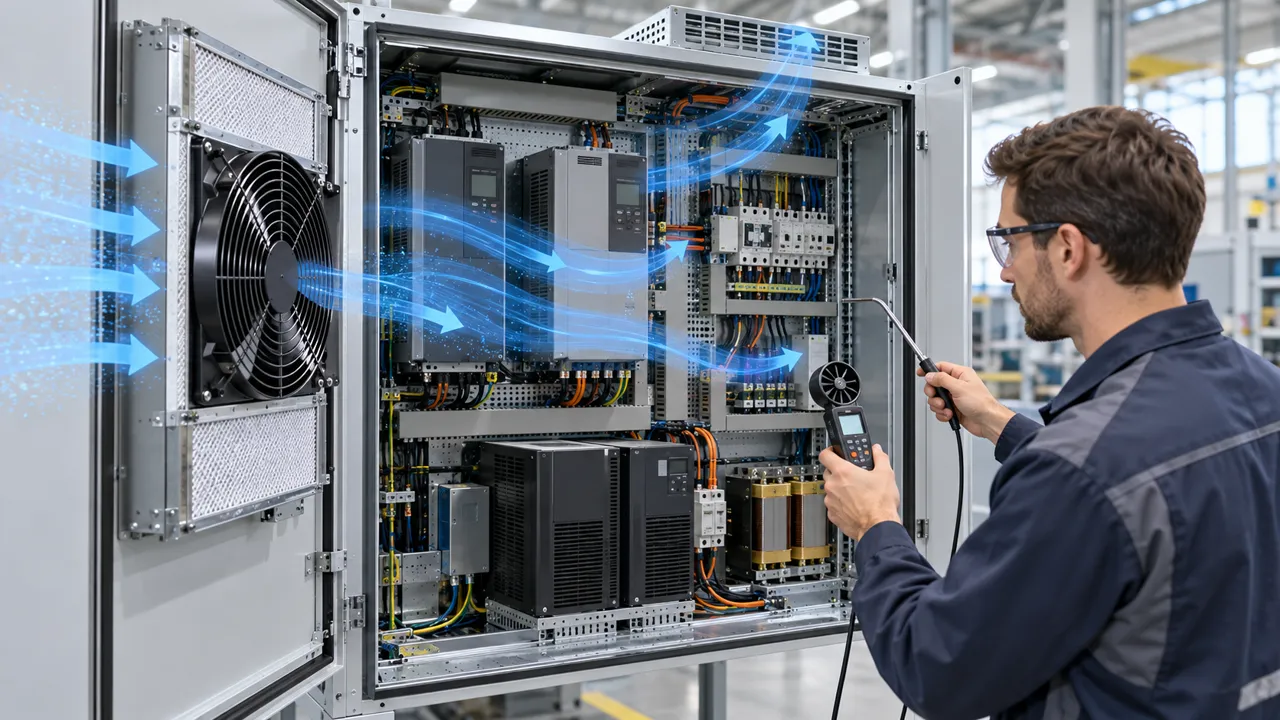
The fan spins on the bench but will not start in the cabinet
An AC fan can pass a free-air test and still fail when a relay, long cable, cold motor and restricted inlet meet at the same moment.
A common field complaint sounds simple: the cabinet fan works when connected directly to a laboratory source, but chatters, starts slowly or remains stopped when the production machine is switched on. Engineers sometimes replace the fan first. The actual cause is often a supply path that collapses during startup, a relay contact that is not rated for the motor load, a long undersized cable, a cold bearing condition, or an inlet filter that makes the motor accelerate against an unexpectedly high load.
This matters in VFD cabinets, UPS enclosures, power supplies, HVACR equipment and industrial control panels because the fan is frequently switched with the main equipment. A brief start failure can leave a power stage heating with no airflow. Repeated failed starts can also stress the switching device and create an intermittent fault that is difficult to reproduce after the cabinet has cooled.
The correct engineering question is not simply whether the fan is rated 110 V or 220 V AC. It is whether the selected configuration starts and continues to operate at the real terminal voltage, frequency, temperature, orientation and system resistance. This guide provides a practical review sequence while keeping the capability boundary clear: MEGA Tech develops and manufactures custom cooling fans; the equipment builder or system integrator owns the cabinet power, protection and control design.
Treat the startup event as part of the thermal design, not as an electrical detail left to purchasing. The first seconds after a power command can coincide with a hot restart, a loaded filter and several other motors energizing. A fan that starts only after the enclosure has already exceeded its temperature limit is not a reliable cooling solution. The design record should therefore connect the electrical start trace to the thermal response and state the conditions under which the sample passed.

Separate supply voltage, terminal voltage and operating frequency
The value on the cabinet nameplate is not automatically the value the motor sees.
Begin the review by listing the source voltage, frequency, protection device, switching device, cable length, conductor size and the fan terminal voltage. The source may be correct while the terminal value is low because of a transformer tap, a shared branch, contact resistance, a long harness or a connector that is not fully seated. Measure at the fan terminals, not only at the distribution point.
Frequency must be recorded beside voltage. AC catalogue data can differ between 50 Hz and 60 Hz, and the speed, current, input power, noise and airflow can move together. A candidate that starts reliably at 60 Hz is not automatically approved for a 50 Hz installation. The product record and the actual site frequency must match the sample test.
Do not hide the measurement basis behind a single phrase such as ‘220 V supply’. Write the actual startup minimum, the steady-state value, the allowed tolerance, and the value measured under the worst simultaneous load. If a control transformer or contactor feeds the fan, include its behavior in the same record.
| Measurement | When to capture it | Why it matters |
|---|---|---|
| Source voltage | Before switching the fan | Shows the available supply, not the motor terminal condition |
| Fan terminal voltage | During inrush and after stabilization | Reveals cable, connector, relay and transformer loss |
| Frequency | At the actual AC source | Determines which catalogue operating data applies |
| Current | At startup and steady state | Separates acceleration behavior from continuous load |
| Airflow or pressure | At the installed restriction | Confirms that a running motor is delivering useful cooling |
What startup current can and cannot tell you
A current spike is evidence of motor acceleration, not proof of a fault by itself.
An AC motor normally draws a different current during acceleration than after it reaches speed. The exact waveform depends on the motor design, fan load, temperature, frequency and measurement instrument. A clamp meter with a slow update rate may show only a smoothed value, while a power analyser or oscilloscope-based measurement can capture the short event. Use the instrument appropriate to the acceptance question and record its bandwidth or peak-capture method.
The useful comparison is repeatability. Measure several starts from the same temperature and then repeat after the fan has been idle, after the cabinet has warmed, and with the production restriction fitted. If the fan starts cleanly and the current settles consistently, the result is more meaningful than one isolated peak. If current remains high while speed is slow, investigate terminal voltage, bearing condition, interference, mounting distortion and the pressure load.
Never turn a measured current into an invented universal limit. The catalogue record and the project protection design govern the acceptable value. A current reading also cannot prove airflow: a fan can draw normal current while an incorrectly fitted filter, blocked grille or bypass path leaves the protected component hot. Pair electrical readings with speed, pressure or airflow and temperature.
For multi-fan equipment, test both one-fan and all-fan startup. Simultaneous switching can multiply the transient demand and create a shared branch dip even when each individual fan passes. Staggered starting may solve the electrical event, but it must not leave the enclosure without sufficient airflow during the sequence. Record fan order, delay, terminal voltage and temperature rise. If the fans are arranged in parallel, also check reverse flow through an idle fan and confirm that a failed or unpowered position does not create a bypass path. These are system-level observations, but they define the fan specification that the supplier must validate.
Find voltage sag across the complete power path
The fastest diagnosis is a synchronized comparison of source voltage, fan-terminal voltage and current.
Connect voltage measurement at the supply and directly at the fan terminals, then trigger both channels when the switching command is applied. The difference between the two waveforms identifies loss in the branch. Inspect the relay or contactor separately: a worn contact can create heat and drop voltage only under load, which is why an unloaded continuity check may look normal.
Cable and connector checks should include crimp quality, terminal torque, conductor gauge, routing near hot components and the number of intermediate plugs. If the fan shares a branch with a compressor, solenoid or power converter, capture the event while those loads switch as they do in production. A clean bench supply cannot reproduce that interaction. Photograph the terminal condition and note whether measurements were taken before or after the enclosure was warmed, because a connector that passes cold may become a larger source of loss after continuous operation.
The design review should define a pass condition before testing. For example, require the fan to complete startup without relay chatter, reach stable operation within the project time window, and maintain the required airflow or pressure at the measured terminal voltage. Add a maximum permitted restart delay and a minimum thermal margin so that the requirement can be judged by different test engineers. The exact voltage margin belongs to the verified product and system specification; do not substitute a generic internet threshold.
It is also useful to distinguish an electrical start failure from a thermal or air-side failure. If the motor never accelerates, begin with terminal voltage, switching and mechanical interference. If it accelerates but the protected part remains hot, move to pressure, bypass, recirculation and component placement. If it starts repeatedly but trips protection, compare the captured event with the switching device and branch design. This fault tree prevents a larger fan from being installed before the real cause is known.
Restriction changes the startup problem
Filters and grilles are not only steady-state pressure losses; they can change the load seen during acceleration and expose marginal power paths.
Fit the production filter, grille, guard, louvre and gasket before drawing conclusions. A small free area can increase face velocity and pressure loss. A dirty or incorrectly seated filter can make the fan operate farther from its free-air condition. In some assemblies, the motor can still reach speed but the useful airflow collapses; in others, the added load makes startup slower and exposes a voltage-sag problem.
Plot or measure the installed system resistance at more than one airflow point when possible. Overlay the appropriate AC fan P-Q curve at the real voltage and frequency. The operating point is the intersection of the fan curve and the system curve, not the maximum airflow printed on a card. If the design is close to the edge, increase filter area, reduce bypass, improve the cutout or review the fan configuration before raising the protection rating.
Check both directions of installation. An exhaust fan can be starved by a narrow inlet, while an inlet fan can discharge into a crowded heat-sink region. A fan that sounds normal at the door may be short-circuiting air around the hot component. Use smoke or a simple flow visualisation carefully, then confirm with temperature and pressure measurements.
Cold start, hot restart and repeated switching
The production duty cycle must include the starts that the equipment will actually make.
Test at the low and high ambient conditions defined for the equipment, within the verified product record. Cold grease behavior, material contraction and a stiff bearing can change acceleration. A hot restart can expose a different issue: the motor, enclosure and switching device are already warm, and the fan may restart while the heat load is still present. The acceptance record should state the wait time between stops and starts.
Repeated cycling is especially important when a thermostat, pressure switch or PLC output controls the fan. Record contact chatter, delayed starts, current settling and the temperature response over a representative sequence. Do not use a short manual toggle as a substitute for the actual controller if the controller has debounce, minimum-on time or alarm logic. Include the restart interval that the machine can create during an alarm recovery or an operator reset; a fan that passes one start may behave differently when its winding and frame are still warm.
Noise and vibration should be recorded after thermal stabilization. A fan can start electrically yet develop rubbing or tonal noise when the frame, guard and panel reach operating temperature. Check mounting torque, gasket compression, cable clearance and any change in sound when the filter is installed.
Protection and switching are system responsibilities
The fan manufacturer can define the fan input requirements, but the cabinet designer must coordinate protection and control around the real installation.
Select the switching device from the verified fan electrical data and the switching duty, not from the steady-state current alone. Consider the number of fans switched together, the source impedance, contact rating, inrush behavior, fuse or breaker coordination and the effect of a failed fan. If several fans start at once, a shared voltage dip can be larger than the result from one sample.
Keep the control logic explicit. A thermostat may switch at one temperature and release at another; a PLC may supervise a contactor; an alarm may indicate loss of airflow rather than loss of electrical power. The acceptance plan should test the signal that the customer actually uses and confirm what happens after a brownout or a rapid power interruption.
MEGA Tech does not supply the complete cabinet, controller, protection scheme, coil, liquid loop or system safety design. We can review the fan-side requirements, develop a custom cooling fan, review the air path and validate samples on the customer's equipment. The system integrator remains responsible for the electrical architecture and protective coordination.
A practical installed validation sequence
Use the same evidence package for a first sample, a substitute review and a production change.
First freeze configuration: fan series and type, voltage, frequency, bearing, mounting orientation, guard, filter, cable and switching device. Photograph the assembly and identify every component that can affect the power path or airflow path. A substitute must be evaluated as a configuration, not as a bare frame size.
Second capture electrical evidence: source voltage, terminal voltage, frequency, startup current, steady current, input power, startup time and any relay chatter. Record the instruments and sampling method. Third capture thermal and air-side evidence: inlet temperature, protected component temperatures, airflow or pressure at the installed point, and noise after stabilization.
Fourth repeat the test at the defined operating modes: cold start, hot restart, simultaneous equipment start, production filter, expected service condition and controller cycling. Fifth review the result against written project limits. If it fails, change one variable at a time so the corrective action is traceable. Keep the raw traces with the sample record, because a summary current value cannot show whether the relay chattered, the voltage dipped briefly or the fan accelerated late.
- Use the actual 50 Hz or 60 Hz source and measure at the fan terminals.
- Capture startup and steady current with a method that can see the complete event.
- Fit the production filter, grille, guard and cable before approving airflow.
- Repeat cold start, hot restart, power interruption and controller cycling.
- Record protected-component temperature together with airflow or pressure.
- Freeze the exact sample configuration before comparing a replacement.
How MEGA Tech supports the fan-side decision
A useful recommendation starts with operating conditions, then ends with a sample on the customer's unit.
MEGA Tech develops and manufactures custom cooling fans for equipment builders. Our review can cover fan selection, the air path, sample validation and the transition to volume production. For AC applications, send the required envelope, voltage, frequency, target airflow, target static pressure, quantity, noise target, mounting orientation, filter or grille, ambient range and switching method.
The selection should be made from the operating point rather than from a part number or outline dimension. If startup is the concern, include the source and terminal-voltage measurements, cable and contactor arrangement, expected cycling and the thermal condition at startup. If the fan is being replaced, include the original installed duty point and the reason the change is required.
We are the custom cooling-fan manufacturer. The complete machine, cabinet, coil, liquid circuit, controller and system integration remain with the equipment manufacturer or system integrator. Samples can be requested for review on the customer's actual unit; send the requirements to inquiry@cnmegatech.com or contact MEGA Tech on WhatsApp at +86 135 7056 7086.
Engineer FAQ
Short answers for a design review when an AC fan will not start reliably.
Q: Is a high startup current automatically a failed fan? A: No. Compare repeatable acceleration, terminal voltage, settling current and installed airflow with the verified product and system limits.
Q: Why does the fan start directly but not through the cabinet switch? A: Check terminal voltage during switching, contact resistance, cable drop, shared loads, frequency and the actual switching device.
Q: Can I approve from the nominal 110 V or 220 V label? A: No. Match the actual voltage and frequency, then measure the fan terminals during startup and operation.
Q: Does normal current prove normal cooling? A: No. Confirm the installed pressure or airflow and protected-component temperature with the production filter and grille fitted.
Q: What should I send for a sample recommendation? A: Send size, voltage, frequency, airflow, static pressure, quantity, noise target, control or switching method, environment and installation details.
Questions for your next AC fan design review
Use these questions to convert an intermittent startup complaint into a testable engineering requirement for design review and production release.
A good review closes the loop between the electrical trace and the cooling result. Keep the source record, terminal waveform, operating-point measurement, temperature map and sample configuration together. That package lets the equipment team distinguish a fan selection issue from a cabinet wiring issue and gives a clear basis for a controlled redesign or production approval. It also makes later substitutions safer because the next sample can be compared against the same evidence instead of a nominal frame size alone. This record should travel with the released drawing and test report.
- What voltage and frequency are present at the fan terminals during the first startup cycle?
- Which relay, contactor, cable, connector and shared loads are in the branch?
- What startup and steady current does the instrument actually capture, and how repeatable is it?
- Does the production filter or grille move the operating point outside the required airflow and pressure range?
- What happens during cold start, hot restart, simultaneous equipment start and rapid power interruption?
- Which protected component temperature and airflow or pressure values define pass or fail?
- Is the selected fan configuration frozen by voltage, frequency, bearing, mounting, guard, filter and cable arrangement?
- What must be sent to MEGA Tech for a custom sample review: size, voltage, frequency, airflow, pressure, quantity, noise and environment?
